John Deere DB44 Planters Installation Instructions Manual A109654C- PDF DOWNLOAD
$27.95
John Deere DB44 Planters Installation Instructions Manual A109654C- PDF DOWNLOAD
Individual Row Hydraulic
Downforce for DB44
Planters
Description
John Deere DB44 Planters Installation Instructions Manual A109654C- PDF DOWNLOAD
FILE DETAILS:
John Deere DB44 Planters Installation Instructions Manual A109654C- PDF DOWNLOAD
Language :English
Pages :114
Downloadable : Yes
File Type : PDF
IMAGES PREVIEW OF THE MANUAL:
DESCRIPTION:
John Deere DB44 Planters Installation Instructions Manual A109654C- PDF DOWNLOAD
Individual Row Hydraulic
Downforce for DB44
Planters
General
Face-Seal-Fitting Assembly and Installation—All Pressure Applications
Face-Seal O-Ring to Stud End Installation
TABLE OF CONTENTS:
John Deere DB44 Planters Installation Instructions Manual A109654C- PDF DOWNLOAD
Individual Row Hydraulic
Downforce for DB44
Planters
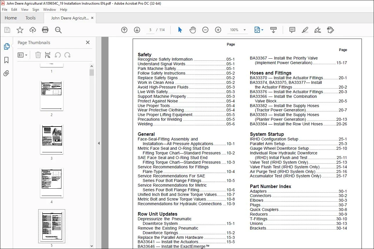
Contents 5
Safety 7
Recognize Safety Information 7
Understand Signal Words 7
Park Machine Safely 7
Follow Safety Instructions 8
Replace Safety Signs 8
Work in Clean Area 8
Avoid High-Pressure Fluids 9
Live With Safety 9
Support Machine Properly 9
Protect Against Noise 10
Use Proper Tools 10
Wear Protective Clothing 10
Use Proper Lifting Equipment 11
Precautions for Welding 11
Welding 12
General 13
Face-Seal-Fitting Assembly and Installation—All Pressure Applications 13
Metric Face Seal and O-Ring Stud End Fitting Torque Chart—Standard Pressures 14
SAE Face Seal and O-Ring Stud End Fitting Torque Chart—Standard Pressures 15
Service Recommendations For Flare-Type Tube Fittings 16
Service Recommendations For SAE Series Four Bolt Flange Fittings 17
Service Recommendations for Metric Series Four Bolt Flange Fitting 18
Unified Inch Bolt and Screw Torque Values 19
Metric Bolt and Screw Torque Values 20
Recommendations for Hydraulic Connections 21
Row Unit Updates 24
Depressurize the Pneumatic Downforce System 24
Remove the Existing Pneumatic Downforce Springs 25
Replace the Parallel Arm Hardware 26
BA33641 — Install the Actuators 28
BA33646 — Install the ExactEmerge™ Row Unit Harness 32
BA33647 — Install the MaxEmerge™ 5e Row Unit Harness 34
BA32946 and BA33294 — Remove and Install the Downforce Sensor 38
BA33644 — Install the Safety Decals 39
BA33367 — Install the Priority Valve (Implement Power Generation) 40
Hoses and Fittings 42
BA33370 — Install the Actuator Fittings 42
BA33374, BA33375, BA33377— Install the Actuator Fittings 43
BA33376 — Install the Actuator Fittings 44
BA33366 — Install the Combination Valve Block 46
BA33382 — Install the Supply Hoses (Tractor Power Generation) 48
BA33383 — Install the Supply Hoses (Planter Power Generation) 54
BA33384 — Install the Row Unit Hoses 67
System Startup 81
IRHD Configuration Setup 81
Parallel Arm Setup 83
Gauge Wheel Downforce Setup 90
Individual Row Hydraulic Downforce (IRHD) Initial Flush and Test 91
Valve Test (IRHD System Only) 93
Valve Flush Test (IRHD System Only) 94
Air Purge Test (IRHD System Only) 96
Accumulator Test (IRHD System Only) 97
Part Number Index 98
Adapters 98
Connectors 99
Elbows 100
Plugs 104
Quick Couplers 105
Reducers 106
T-Fittings 107
Unions 110
Brackets 111
Page Number 5
Section 05 7
Section 10 13
Section 15 24
Section 20 42
Section 25 81
Section 30 98
S.M 8/3/2025