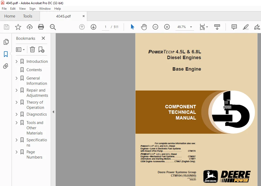
John Deere POWERTECH 4.5L & 6.8L Diesel Engines Base Engine Technical Manual – PDF DOWNLOAD
Original price was: $89.95.$28.95Current price is: $28.95.
John Deere POWERTECH 4.5L & 6.8L Diesel Engines Base Engine Technical Manual – PDF DOWNLOAD
Description
John Deere POWERTECH 4.5L & 6.8L Diesel Engines Base Engine Technical Manual – PDF DOWNLOAD
DESCRIPTION :
John Deere POWERTECH 4.5L & 6.8L Diesel Engines Base Engine Technical Manual – PDF DOWNLOAD
For complete service information also see:
POWERTECH® 4.5 L and 6.8 L Diesel
Engines—Level 4 Electronic Fuel Systems
with Bosch VP44 Pump . . . . . . . . . . . . . . . . . CTM170
POWERTECH® 4.5 L and 6.8 L Diesel
Engines—Mechanical Fuel Systems. . . . . . . CTM207
Alternators and Starting Motors . . . . . . . . . . CTM77
OEM Engine Accessories. . . . . . . . . CTM67 (English Only)
Forward :
This manual is written for an experienced technician. Essential tools required in performing certain service work are identified in this manual and are recommended for use.
This manual (CTM104) covers only the base engine. It is one of three volumes on 4.5 L and 6.8 L engines. The following two companion manuals cover fuel system repair, operation and diagnostics:
· CTM170—Level 4 Electronic Fuel Systems with
Bosch VP44 Pump
· CTM207—Mechanical Fuel Systems
CTM207 covers the fuel systems formerly included in
CTM104.
- Other manuals will be added in the future to provide additional information on electronic fuel systems as needed. A complete set of all three manuals covering the 4.5 L and 6.8 L engines can be procured by ordering CTM350 Binder Set.
- Live with safety: Read the safety messages in the introduction of this manual and the cautions presented throughout the text of the manual.
TABLE OF CONTENTS:
John Deere POWERTECH 4.5L & 6.8L Diesel Engines Base Engine Technical Manual – PDF DOWNLOAD
Introduction…………………………………………………………………………………………………. 2
Forward………………………………………………………………………………………………….. 2
John Deere Dealers………………………………………………………………………………………… 3
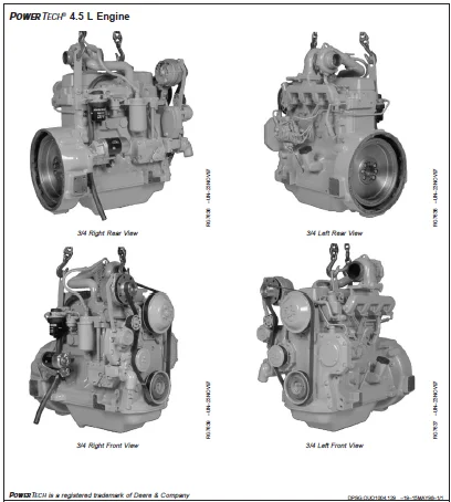
POWERTECH® 4.5 L Engine……………………………………………………………………………………. 5
POWERTECH® 6.8 L Engine……………………………………………………………………………………. 6
Contents…………………………………………………………………………………………………….. 7
General Information…………………………………………………………………………………………… 9
Safety…………………………………………………………………………………………………… 11
Handle Fluids Safely—Avoid Fires………………………………………………………………………… 11
Handle Starting Fluid Safely……………………………………………………………………………. 11
Service Cooling System Safely…………………………………………………………………………… 12
Prevent Battery Explosions……………………………………………………………………………… 12
Prepare for Emergencies………………………………………………………………………………… 13
Handling Batteries Safely………………………………………………………………………………. 14
Avoid High-Pressure Fluids……………………………………………………………………………… 15
Wear Protective Clothing……………………………………………………………………………….. 15
Service Machines Safely………………………………………………………………………………… 16
Work In Ventilated Area………………………………………………………………………………… 16
Work in Clean Area…………………………………………………………………………………….. 17
Remove Paint Before Welding or Heating…………………………………………………………………… 17
Avoid Heating Near Pressurized Fluid Lines……………………………………………………………….. 18
Illuminate Work Area Safely…………………………………………………………………………….. 18
Use Proper Lifting Equipment……………………………………………………………………………. 19
Construct Dealer-Made Tools Safely………………………………………………………………………. 19
Practice Safe Maintenance………………………………………………………………………………. 20
Use Proper Tools………………………………………………………………………………………. 20
Dispose of Waste Properly………………………………………………………………………………. 21
Live With Safety………………………………………………………………………………………. 21
Engine Identification……………………………………………………………………………………… 23
Engine Model Designation……………………………………………………………………………….. 23
Engine Serial Number Plate Information ………………………………………………………………….. 24
OEM Engine Option Code Label……………………………………………………………………………. 25
Engine Application Charts………………………………………………………………………………. 26
Fuels, Lubricants and Coolants……………………………………………………………………………… 33
Diesel Fuel ………………………………………………………………………………………….. 33
Lubricity of Diesel Fuel……………………………………………………………………………….. 33
Engine Break-In Oil …………………………………………………………………………………… 34
Diesel Engine Oil …………………………………………………………………………………….. 35
Extended Diesel Engine Oil Service Intervals……………………………………………………………… 35
Alternative and Synthetic Lubricants ……………………………………………………………………. 36
Mixing of Lubricants…………………………………………………………………………………… 36
OILSCAN®, OILSCAN Plus® and COOLSCAN™ …………………………………………………………………… 37
Grease……………………………………………………………………………………………….. 38
Diesel Engine Coolant Recommendations……………………………………………………………………. 39
Engine Coolant Specifications…………………………………………………………………………… 40
Testing Diesel Engine Coolant ………………………………………………………………………….. 43
Replenishing Supplemental Coolant Additives (SCAs) Between Coolant Changes…………………………………… 44
Operating in Warm Temperature Climates…………………………………………………………………… 45
Flush and Service Cooling System………………………………………………………………………… 46
Disposing of Coolant…………………………………………………………………………………… 47
Repair and Adjustments………………………………………………………………………………………… 49
Engine Rebuild……………………………………………………………………………………………. 53
Engine Overhaul Guidelines……………………………………………………………………………… 53
Engine Repair Stand……………………………………………………………………………………. 53
Engine Stand Safety Precautions ………………………………………………………………………… 54
Install Adapters on Engine Repair Stand………………………………………………………………….. 55
Engine Lifting Procedure……………………………………………………………………………….. 56
Clean Engine………………………………………………………………………………………….. 57
Disconnect Turbocharger Oil Inlet Line…………………………………………………………………… 58
Mount Engine on Repair Stand……………………………………………………………………………. 59
Engine Mounted on Repair Stand………………………………………………………………………….. 60
Engine Disassembly Sequence…………………………………………………………………………….. 61
Sealant Application Guidelines………………………………………………………………………….. 63
Engine Assembly Sequence……………………………………………………………………………….. 65
Engine Break-In Guidelines …………………………………………………………………………….. 67
Perform Engine Break-In ……………………………………………………………………………….. 68
Cylinder Head and Valves…………………………………………………………………………………… 71
Check and Adjust Valve Clearance………………………………………………………………………… 71
Measure Valve Lift…………………………………………………………………………………….. 74
Remove Cylinder Head…………………………………………………………………………………… 76
Disassemble and Inspect Rocker Arm Shaft Assembly…………………………………………………………. 83
Assemble Rocker Arm Assembly……………………………………………………………………………. 84
Inspect, Measure, and Install Fuel Supply Pump Push Rod—If Applicable……………………………………….. 84
Inspect, Measure, and Assemble Camshaft Followers…………………………………………………………. 86
Measure Valve Recess in Cylinder Head……………………………………………………………………. 88
Preliminary Cylinder Head and Valve Checks ………………………………………………………………. 89
Remove Valve Assembly………………………………………………………………………………….. 90
Inspect and Measure Valve Springs……………………………………………………………………….. 90
Inspect Valve Rotators…………………………………………………………………………………. 91
Clean Valves………………………………………………………………………………………….. 91
Inspect and Measure Valves……………………………………………………………………………… 92
Grind Valves………………………………………………………………………………………….. 93
Head Gasket Inspection and Repair Sequence……………………………………………………………….. 94
Inspect and Clean Cylinder Head…………………………………………………………………………. 95
Check Cylinder Head Flatness……………………………………………………………………………. 96
Measure Cylinder Head Thickness…………………………………………………………………………. 97
Clean Injection Nozzle Bores……………………………………………………………………………. 98
Clean Valve Guides…………………………………………………………………………………….. 98
Measure Valve Guides…………………………………………………………………………………… 99
Knurl Valve Guides……………………………………………………………………………………..100
Clean and Inspect Valve Seats……………………………………………………………………………100
Grind Valve Seats………………………………………………………………………………………101
Remove Valve Seat Inserts……………………………………………………………………………….103
Measure Valve Seat Bore in Cylinder Head………………………………………………………………….106
Install Valve Seat Inserts………………………………………………………………………………107
Install Valves…………………………………………………………………………………………107
Clean and Inspect Cylinder Head Cap Screws………………………………………………………………..108
Inspect and Clean Exhaust Manifold……………………………………………………………………….108
Clean and Inspect Top Deck of Cylinder Block………………………………………………………………109
Measure Cylinder Liner Standout (Height above Block)……………………………………………………….110
Install Cylinder Head…………………………………………………………………………………..110
Torque-Turn Method for Proper Torque……………………………………………………………………..113
Install Rocker Arm Assembly……………………………………………………………………………..114
Inspect and Clean Ventilator Outlet Hose………………………………………………………………….114
Install Rocker Arm Cover………………………………………………………………………………..115
Complete Final Assembly…………………………………………………………………………………116
Cylinder Block, Liners, Pistons and Rods……………………………………………………………………..121
Connecting Rods—General Information………………………………………………………………………121
Remove Pistons and Connecting Rods ………………………………………………………………………122
Remove Cylinder Liners………………………………………………………………………………….125
Complete Disassembly of Cylinder Block (If Required)……………………………………………………….127
Preliminary Liner, Piston and Rod Checks …………………………………………………………………128
Disassemble Piston and Rod Assembly ……………………………………………………………………..129
Clean Pistons………………………………………………………………………………………….130
Visually Inspect Pistons………………………………………………………………………………..131
Clean Cylinder Liners…………………………………………………………………………………..132
Visually Inspect Cylinder Liners…………………………………………………………………………133
Check Piston Ring Groove Wear …………………………………………………………………………..135
Measure Piston Pin Bore…………………………………………………………………………………136
Measure Piston Skirt……………………………………………………………………………………136
Measure Piston Height…………………………………………………………………………………..136
Determine Piston-to-Liner Clearance ……………………………………………………………………..137
Deglaze Cylinder Liners…………………………………………………………………………………139
Replace Piston and Liner Sets……………………………………………………………………………139
Inspect and Measure Connecting Rod Bearings (Rods Removed from Engine)……………………………………….140
Inspect and Measure Connecting Rod Bearings (Rod and Crankshaft in Engine)……………………………………141
Inspect Rod and Cap…………………………………………………………………………………….142
Inspect Piston Pins and Bushings…………………………………………………………………………144
Remove Piston Pin Bushing……………………………………………………………………………….145
Clean and Inspect Connecting Rod Pin Bore…………………………………………………………………147
Install Piston Pin Bushing in Connecting Rod………………………………………………………………148
Measure Rod Center-to-Center Bores……………………………………………………………………….149
Inspect and Clean Cylinder Block…………………………………………………………………………150
Clean Cylinder Liner O-Ring Bore…………………………………………………………………………152
Measure Cylinder Block Main Bearing Bore………………………………………………………………….153
Measure Camshaft Follower Machined Bore in Block…………………………………………………………..153
Measure Camshaft Bushing Bores in Block…………………………………………………………………..154
Measure Balancer Shaft Bushing ID in Block—4-Cylinder Engines……………………………………………….155
Measure Cylinder Liners and Block Bores ………………………………………………………………….156
Measure Liner Flange Counterbore Depth in Block……………………………………………………………156
Measure Liner Flange Thickness…………………………………………………………………………..157
Measure Cylinder Block Top Deck Flatness………………………………………………………………….157
Remove, Inspect, and Install Piston Cooling Orifices……………………………………………………….158
Measure Fuel Supply Pump Push Rod Bore and Push Rod OD……………………………………………………..159
Measure Cylinder Liner Standout (Height above Block)……………………………………………………….160
Install Packing on Cylinder Liner and O-Rings in Block……………………………………………………..161
Install Cylinder Liner in Block………………………………………………………………………….163
Assemble Piston and Connecting Rod ………………………………………………………………………165
Install Piston Rings……………………………………………………………………………………166
Install Piston and Connecting Rod Assembly ……………………………………………………………….167
Torque-Turn Connecting Rod Cap Screws…………………………………………………………………….171
Check Engine Rotation for Excessive Tightness……………………………………………………………..172
Measure Piston Protrusion……………………………………………………………………………….173
Complete Final Assembly…………………………………………………………………………………174
Crankshaft, Main Bearings and Flywheel……………………………………………………………………….175
Crankshaft and Main Bearing Failure Analysis ……………………………………………………………..175
Inspect Vibration Damper………………………………………………………………………………..176
Remove Pulley or Vibration Damper and Pulley ……………………………………………………………..177
Install Pulley or Vibration Damper and Pulley …………………………………………………………….178
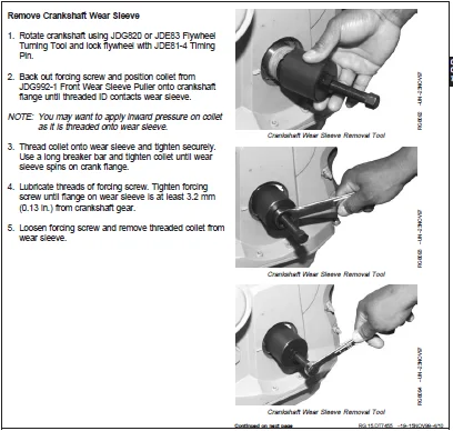
Replace Front Crankshaft Oil Seal and Wear Sleeve …………………………………………………………179
Check Crankshaft End Play……………………………………………………………………………….186
Inspect Flywheel……………………………………………………………………………………….186
Check Flywheel Face Flatness…………………………………………………………………………….187
Check Pilot Bearing Bore Concentricity …………………………………………………………………..187
Remove Flywheel………………………………………………………………………………………..188
Replace Flywheel Ring Gear………………………………………………………………………………189
Replace Pilot Bearing in Flywheel—If Equipped……………………………………………………………..190
Install Flywheel……………………………………………………………………………………….191
Crankshaft Rear Oil Seal and Wear Sleeve Handling Precautions……………………………………………….192
Remove Crankshaft Rear Oil Seal and Wear Sleeve …………………………………………………………..192
Clean and Inspect Crankshaft Flange………………………………………………………………………197
Install Crankshaft Rear Oil Seal and Wear Sleeve…………………………………………………………..197
Remove Flywheel Housing…………………………………………………………………………………200
Remove and Install Crankshaft Timing Wheel (Engines with VP44 Fuel Injection Pump) ……………………………201
Remove Crankshaft Main Bearings …………………………………………………………………………202
Check Main Bearing Oil Clearance ………………………………………………………………………..203
Remove and Install Crankshaft Gear (Crankshaft Installed in Engine)………………………………………….204
Remove Crankshaft………………………………………………………………………………………206
Inspect Crankshaft……………………………………………………………………………………..207
Measure Crankshaft Journals and Main Bearing ID …………………………………………………………..208
Measure Main Thrust Journal Width and Thrust Bearing Width………………………………………………….209
Crankshaft Grinding Guidelines…………………………………………………………………………..210
Crankshaft Grinding Specifications……………………………………………………………………….211
Measure Assembled ID of Main Bearing Caps ………………………………………………………………..212
Remove, Inspect, and Install Piston Cooling Orifices……………………………………………………….213
Install Main and Thrust Bearing Inserts in Block…………………………………………………………..214
Install Crankshaft……………………………………………………………………………………..216
Install Flywheel Housing………………………………………………………………………………..219
Complete Final Assembly…………………………………………………………………………………221
Camshaft, Balancer Shafts and Timing Gear Train……………………………………………………………….223
Measure Valve Lift……………………………………………………………………………………..223
Remove Timing Gear Cover………………………………………………………………………………..225
Remove and Install Camshaft Bushing with Front Plate Installed………………………………………………228
Remove and Install Camshaft Gear-Driven Auxiliary Drive…………………………………………………….232
Measure Camshaft End Play……………………………………………………………………………….233
Measure Balancer Shaft End Play (4-Cylinder Engines)……………………………………………………….233
Measure Idler Gear End Play……………………………………………………………………………..234
Measure Timing Gear Backlash…………………………………………………………………………….234
Remove Camshaft………………………………………………………………………………………..235
Visually Inspect Camshaft……………………………………………………………………………….237
Measure Camshaft Thrust Plate Clearance and Thickness………………………………………………………238
Inspect and Measure Camshaft Bushing ID and Journal OD……………………………………………………..239
Measure Camshaft Lobe Height…………………………………………………………………………….240
Remove and Install Camshaft Gear…………………………………………………………………………240
Inspect Camshaft Followers………………………………………………………………………………241
Inspect, Measure, and Install Fuel Supply Pump Push Rod…………………………………………………….242
Remove Balancer Shafts—If Equipped (4-Cylinder Engines)…………………………………………………….243
Inspect and Measure Balancer Shaft Bushings and Journals……………………………………………………244
Remove and Install Balancer Shaft Bushings (4-Cylinder Engines)……………………………………………..245
Inspect Balancer Shaft Gears and Thrust Plates…………………………………………………………….246
Remove and Install Balancer Shaft Gears…………………………………………………………………..246
Remove Cylinder Block Front Plate………………………………………………………………………..247
Measure Idler Gear Bushing and Shaft……………………………………………………………………..250
Remove Idler Gear Bushings………………………………………………………………………………251
Install Idler Gear Bushings……………………………………………………………………………..252
Remove Lower and Upper Idler Shafts………………………………………………………………………253
Clean and Inspect Front Plate……………………………………………………………………………253
Transfer Fuel Injection Pump Timing Mark onto Replacement Front Plate ……………………………………….254
Install Idler Shaft Spring Pins (If Equipped)……………………………………………………………..255
Install Upper Idler Shaft in Front Plate………………………………………………………………….255
Install Lower Idler Shaft in Front Plate………………………………………………………………….256
Install Cylinder Block Front Plate……………………………………………………………………….256
Install and Time Balancer Shafts (4-Cylinder Engines)………………………………………………………258
Install Camshaft……………………………………………………………………………………….262
Clean and Inspect Timing Gear Cover………………………………………………………………………265
Install Timing Gear Cover……………………………………………………………………………….266
Install Crankshaft Front Wear Sleeve and Oil Seal …………………………………………………………268
Remove and Install Magnetic Pick-Up Sensor ……………………………………………………………….270
Replace Mechanical Tachometer Adapter…………………………………………………………………….271
Complete Final Assembly…………………………………………………………………………………272
Lubrication System…………………………………………………………………………………………273
General Lubrication System Information……………………………………………………………………273
Remove, Inspect, and Install Oil Filter Base………………………………………………………………273
Remove, Inspect, and Install Oil Cooler…………………………………………………………………..277
Remove, Inspect, and Install Oil Bypass Valve……………………………………………………………..281
Remove and Install Oil Pressure Regulating Valve and Seat…………………………………………………..281
Remove and Install Oil Fill Tube…………………………………………………………………………284
Remove and Install Dipstick Tube with Oil Pan Installed…………………………………………………….285
Remove and Install Dipstick Tube with Fitting……………………………………………………………..286
Remove, Inspect and Install Oil Pump Pick-Up Tube Assembly………………………………………………….287
Engine Oil Pump Assembly………………………………………………………………………………..287
Remove Engine Oil Pump………………………………………………………………………………….288
Inspect and Measure Clearances…………………………………………………………………………..289
Complete Oil Pump Disassembly……………………………………………………………………………291
Assemble Engine Oil Pump………………………………………………………………………………..292
Install Engine Oil Pump…………………………………………………………………………………293
Install Oil Pan………………………………………………………………………………………..295
Cooling System…………………………………………………………………………………………….297
Remove Water Manifold/Thermostat Cover and Thermostat ……………………………………………………..297
Install Water Manifold/Thermostat Cover and Thermostat …………………………………………………….298
Remove and Install Water Manifold/Thermostat Cover and Thermostat (6010 Series Tractors with Single Thermostat) ….300
Remove and Install Water Manifold and Thermostats (Dual Thermostats) ………………………………………..303
Test Thermostat(s)……………………………………………………………………………………..304
Remove Water Pump………………………………………………………………………………………305
Water Pump Assembly…………………………………………………………………………………….306
Disassemble Water Pump………………………………………………………………………………….307
Inspect, Clean, and Measure Water Pump Parts………………………………………………………………308
Assemble Water Pump…………………………………………………………………………………….309
Install Water Pump……………………………………………………………………………………..310
Cooling System Deaeration……………………………………………………………………………….311
Remove and Install Automatic (Spring) Belt Tensioner……………………………………………………….312
Checking Belt Tensioner Spring Tension and Belt Wear……………………………………………………….312
Manual Belt Tensioner Adjustment ………………………………………………………………………..314
Inspect and Install Fan Assembly…………………………………………………………………………315
Remove and Inspect Fan Drive Assembly…………………………………………………………………….316
Replace Bearings in Adjustable Fan Drive Assembly………………………………………………………….317
Install Fan Drive Assembly………………………………………………………………………………320
Remove and Install Fan Drive Assembly (2254 Combine)……………………………………………………….323
Remove and Install Coolant Heater—If Equipped……………………………………………………………..324
Remove and Install Cold Start Advance Switch (If Equipped)………………………………………………….325
Air Intake and Exhaust System……………………………………………………………………………….327
Extending Turbocharger Life……………………………………………………………………………..327
Remove Turbocharger…………………………………………………………………………………….329
Turbocharger Failure Analysis……………………………………………………………………………330
Turbocharger Seven-Step Inspection……………………………………………………………………….332
Perform Radial Bearing Clearance Test…………………………………………………………………….339
Perform Axial Bearing End Play Test………………………………………………………………………340
Adjust Turbocharger Wastegate Actuator (If Equipped)……………………………………………………….341
Repair Turbocharger…………………………………………………………………………………….341
Prelube Turbocharger……………………………………………………………………………………342
Install Turbocharger……………………………………………………………………………………343
Turbocharger Break-In…………………………………………………………………………………..344
Recommendations for Turbocharger Use……………………………………………………………………..345
Remove, Inspect, and Install Exhaust Manifold……………………………………………………………..346
Remove and Install Air-to-Air Aftercooler…………………………………………………………………346
Remove and Install Air Intake Pipe……………………………………………………………………….347
Remove and Install Air Heater……………………………………………………………………………348
Remove and Install Starting Aid—If Equipped……………………………………………………………….349
Fuel System……………………………………………………………………………………………….351
Fuel System……………………………………………………………………………………………351
Starting and Charging Systems……………………………………………………………………………….353
Remove and Install Starter………………………………………………………………………………353
Remove and Install Alternator……………………………………………………………………………354
Theory of Operation……………………………………………………………………………………………357
Base Engine Operation………………………………………………………………………………………359
Base Engine Theory of Operation………………………………………………………………………….359
General Engine Operation………………………………………………………………………………..360
General Engine Operation—Continued……………………………………………………………………….361
Lubrication System Operation ……………………………………………………………………………362
Cooling System Operation ……………………………………………………………………………….364
Head Gasket Joint Construction and Operation………………………………………………………………366
Air Intake and Exhaust System Operation…………………………………………………………………..368
Air Cleaner Operation…………………………………………………………………………………..369
Turbocharger Operation………………………………………………………………………………….370
How the Turbocharger Is Lubricated……………………………………………………………………….370
Diagnostics…………………………………………………………………………………………………..371
Observable Diagnostics and Tests…………………………………………………………………………….373
About This Section of the Manual…………………………………………………………………………373
Diagnosing Lubrication System Malfunctions ……………………………………………………………….373
L1 – Excessive Oil Consumption…………………………………………………………………………..373
Check Oil in Coolant……………………………………………………………………………………374
Check for Excessive Crankcase Pressure (Blow-By)…………………………………………………………..374
Turbocharger Oil Seal Leak Check…………………………………………………………………………375
Pistons, Rings, Cylinder Liners Check…………………………………………………………………….375
L2 – Engine Oil Pressure Low ……………………………………………………………………………376
L3 – Engine Oil Pressure High …………………………………………………………………………..378
Diagnosing Cooling System Malfunctions……………………………………………………………………379
C1 – Engine Coolant Temperature Above Normal ……………………………………………………………..379
C2 – Engine Coolant Temperature Below Normal ……………………………………………………………..380
C3 – Coolant in Oil or Oil in Coolant ……………………………………………………………………380
Test Engine Compression Pressure…………………………………………………………………………381
Test Engine Cranking Speed………………………………………………………………………………384
Dynamometer Test……………………………………………………………………………………….385
Engine Oil Consumption………………………………………………………………………………….386
Check Engine Oil Pressure ………………………………………………………………………………387
Check for Excessive Engine Crankcase Pressure (Blow-By) ……………………………………………………389
Check for Turbocharger Oil Seal Leak……………………………………………………………………..390
Inspect Thermostat and Test Opening Temperature……………………………………………………………391
Pressure Test Cooling System and Radiator Cap …………………………………………………………….392
Check for Head Gasket Failures ………………………………………………………………………….394
Check and Service Cooling System…………………………………………………………………………397
Check Air Intake System…………………………………………………………………………………399
Measure Intake Manifold Pressure (Turbocharger Boost) ……………………………………………………..400
Check for Intake and Exhaust Restrictions ………………………………………………………………..402
Test for Intake Air Leaks……………………………………………………………………………….403
Check for Exhaust Air Leaks (Turbocharged Engines)…………………………………………………………404
Test Turbocharger Wastegate……………………………………………………………………………..404
Test Air Filter Restriction Indicator Switch………………………………………………………………405
Tools and Other Materials………………………………………………………………………………………407
Repair Tools and Other Materials…………………………………………………………………………….409
Cylinder Head and Valves Essential Tools………………………………………………………………….409
Cylinder Head and Valves Service Equipment and Tools……………………………………………………….414
Cylinder Head and Valves Other Materials………………………………………………………………….416
Cylinder Block, Liners, Pistons and Rods Essential Tools……………………………………………………417
Cylinder Block, Liners, Pistons and Rods Service Equipment and Tools…………………………………………422
Cylinder Block, Liners, Pistons and Rods Other Materials……………………………………………………423
Crankshaft, Main Bearings and Flywheel Essential Tools……………………………………………………..424
Crankshaft, Main Bearings and Flywheel Service Equipment and Tools…………………………………………..429
Crankshaft, Main Bearings and Flywheel Other Materials……………………………………………………..430
Camshaft, Balancer Shafts and Timing Gear Train Essential Tools……………………………………………..431
Camshaft, Balancer Shafts and Timing Gear Train Service Equipment and Tools…………………………………..435
Camshaft, Balancer Shafts and Timing Gear Train Other Materials……………………………………………..436
Lubrication System Essential Tools……………………………………………………………………….437
Lubrication System Service Equipment and Tools…………………………………………………………….440
Lubrication System Other Materials……………………………………………………………………….441
Cooling System Essential Tools…………………………………………………………………………..442
Cooling System Service Equipment and Tools………………………………………………………………..443
Cooling System Other Materials…………………………………………………………………………..444
Air Intake and Exhaust System Other Materials……………………………………………………………..445
Starting and Charging System Essential Tools………………………………………………………………446
Diagnostic Service Tools……………………………………………………………………………………447
Diagnostic Essential Tools………………………………………………………………………………447
Diagnostic Service Equipment and Tools……………………………………………………………………449
Dealer Fabricated Service Tools……………………………………………………………………………..451
How to Make Tools ……………………………………………………………………………………..451
DFRG3—Cylinder Liner Holding Fixture……………………………………………………………………..451
DFRG5—Injection Pump Front Plate Timing Mark Transfer Tool………………………………………………….452
Engine Oil Dipstick Tube Driver (6010—6910 Series Tractor Engines)…………………………………………..453
Specifications………………………………………………………………………………………………..455
Repair and General OEM Specifications………………………………………………………………………..457
Unified Inch Bolt and Cap Screw Torque Values …………………………………………………………….457
Metric Bolt and Cap Screw Torque Values ………………………………………………………………….458
General OEM Engine Specifications………………………………………………………………………..459
Engine Rebuild Specifications……………………………………………………………………………459
Cylinder Head and Valves Specifications…………………………………………………………………..460
Cylinder Block, Liners, Pistons and Rods Specifications…………………………………………………….464
Crankshaft, Main Bearings and Flywheel Specifications………………………………………………………470
Camshaft, Balancer Shafts and Timing Gear Train Specifications………………………………………………472
Lubrication System Specifications………………………………………………………………………..477
Cooling System Specifications……………………………………………………………………………480
Air Intake and Exhaust System Specifications………………………………………………………………483
Starting and Charging Systems Specifications ……………………………………………………………..484
Diagnostic Specifications…………………………………………………………………………………..485
Dynamometer Test Specifications………………………………………………………………………….485
Intake Manifold Pressure (Turbocharger Boost) Specifications ……………………………………………….493
Effects of Altitude and Temperature on Engine Performance ………………………………………………….503
Engine Diagnostic Specifications…………………………………………………………………………504
IMAGES PREVIEW OF THE MANUAL:
JOHN DEERE POWERTECH 4.5L & 6.8L DIESEL ENGINES BASE ENGINE TECHNICAL MANUAL – PDF DOWNLOAD:
PLEASE NOTE:
- This is the SAME exact manual used by your dealers to fix your vehicle.
- The same can be yours in the next 2-3 mins as you will be directed to the download page immediately after paying for the manual.
- Any queries / doubts regarding your purchase, please feel free to contact [email protected]
S.V