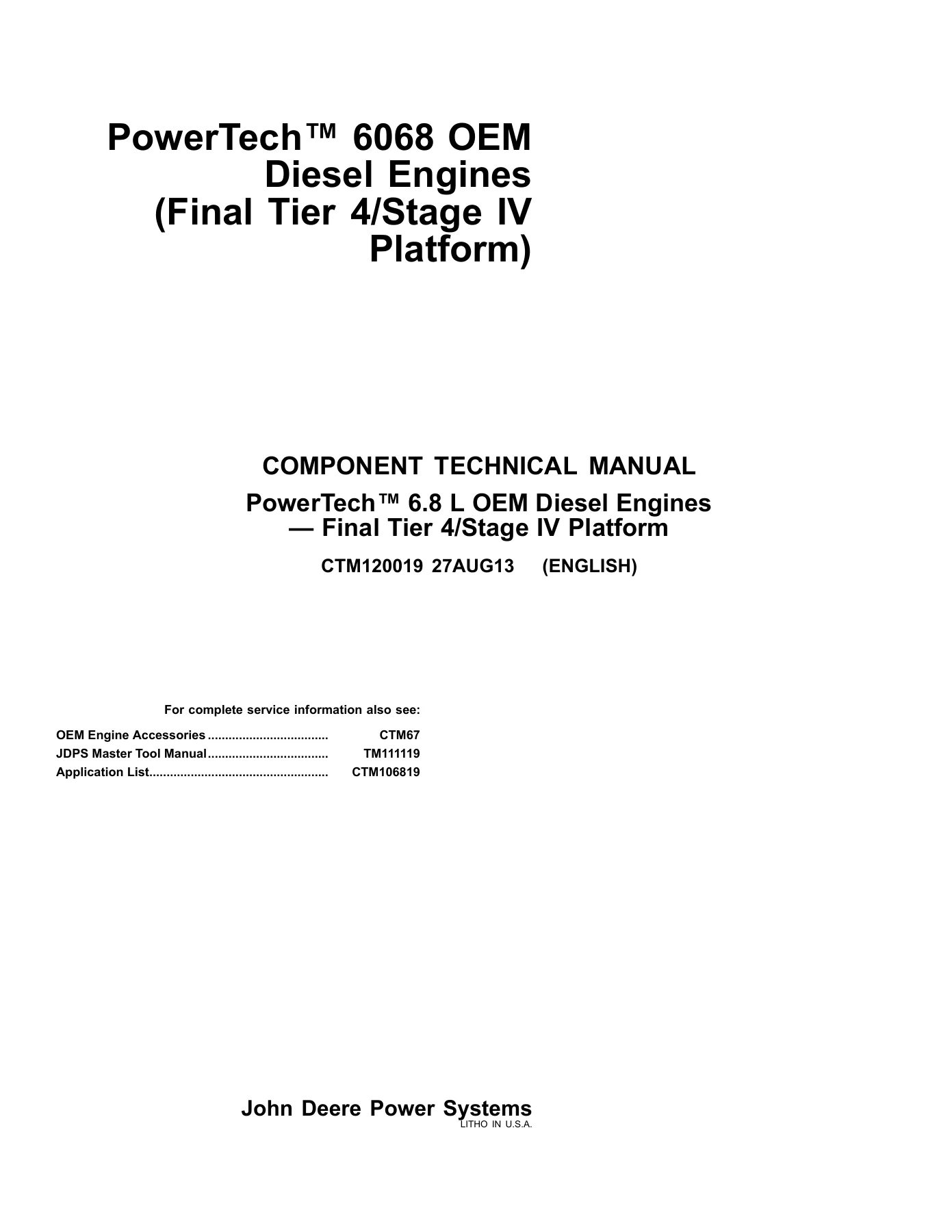
John Deere PowerTech 6068 6.8L Final Tier 4 Component Technical Manual CTM120019 2013 PDF
$34.95 Original price was: $34.95.$19.95Current price is: $19.95.
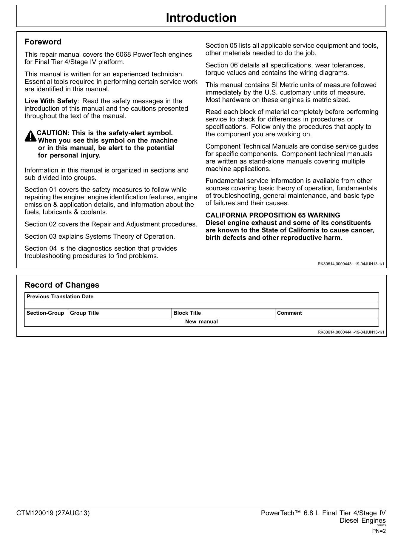
Factory Component Technical Manual for John Deere PowerTech 6068 6.8L Final Tier 4 engines. Publication CTM120019, 2013. Covers service, repair, diagnostics, specifications, and rebuild procedures.
Description
John Deere PowerTech 6068 6.8L Final Tier 4 Component Technical Manual CTM120019
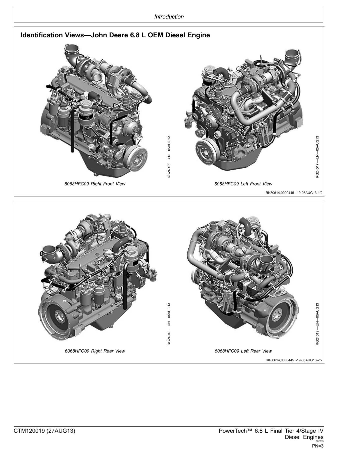
The John Deere PowerTech 6068 6.8L Final Tier 4 Component Technical Manual CTM120019 is the definitive resource for servicing, repairing, and overhauling the PowerTech 6068 engine. Published in 2013, this manual provides detailed procedures, specifications, and diagnostic information for engines meeting Final Tier 4 emissions standards. Whether you are a professional technician or a serious owner-operator, this PDF manual gives you the knowledge to keep your John Deere equipment running at peak performance.
File Details
- Manual Type: Component Technical Manual
- Brand: John Deere
- Model: PowerTech 6068
- Displacement: 6.8L
- Emission Standard: Final Tier 4
- Publication Number: CTM120019
- Publication Year: 2013
- Language: English
- File Format: PDF
IMAGES PREVIEW
Chapters Covered
This manual is organized into comprehensive chapters that cover every major system and component of the PowerTech 6068 engine. The contents include:
- General Information
- Safety Information
- Engine Identification
- Specifications
- Torque Values
- Special Tools
- Engine Removal and Installation
- Cylinder Head and Valve Train
- Cylinder Block
- Pistons and Connecting Rods
- Crankshaft and Main Bearings
- Flywheel
- Camshaft
- Timing Gear Train
- Lubrication System
- Cooling System
- Fuel System
- Air Intake System
- Exhaust System
- Electrical System
- Electronic Control Unit
- Sensors and Actuators
- Connectors
- Wiring Diagrams
- Diagnostic Trouble Codes
- Tests and Adjustments
- Troubleshooting
- Engine Rebuild Procedures
Each chapter provides step-by-step instructions, detailed illustrations, and exact specifications to guide you through every task. From routine maintenance to complex internal engine repairs, the John Deere PowerTech 6068 6.8L Final Tier 4 Component Technical Manual CTM120019 equips you with the information you need to do the job right the first time.
What You Can Do With This Manual
With this manual, you can perform a wide range of procedures, including:
- Diagnose engine performance issues using diagnostic trouble codes and troubleshooting guides.
- Remove and install the engine safely and efficiently.
- Rebuild cylinder heads, including valve train service.
- Inspect and repair the cylinder block, pistons, connecting rods, crankshaft, and main bearings.
- Service the lubrication, cooling, fuel, air intake, and exhaust systems.
- Test and replace electronic control unit components, sensors, and actuators.
- Interpret wiring diagrams for electrical repairs.
- Apply correct torque values and specifications for every fastener and component.
Complete Bookmarks
The complete bookmarks in the “John Deere PowerTech 6068 6.8L Final Tier 4 Component Technical Manual CTM120019 2013 PDF” are as follows:
+Contentsp. 11
+General Informationp. 13
+Safetyp. 15
+Engine Identificationp. 29
+Fuels, Lubricants, and Coolantp. 33
+Repair and Adjustmentsp. 56
+Engine Rebuildp. 57
+Cylinder Head and Valve Repair and Adjustmentp. 73
+Cylinder Block, Liners, Pistons, and Rods Repair and Adjustmentp. 123
+Crankshaft, Main Bearings, Flywheel Repair, and Adjustmentp. 159
+Camshaft and Timing Gear Train Repair and Adjustmentp. 199
+Lubrication System Repair and Adjustmentp. 225
+Cooling Systemp. 245
+Air Intake and Exhaust System Repair and Adjustment – Dual Turbochargerp. 277
+Air Intake and Exhaust System Repair and Adjustment – Single Turbochargerp. 345
+Electronic Fuel System Repair and Adjustmentp. 383
+OEM Starting and Charging Systems Repair and Adjustmentp. 425
+Electrical Engine Control Repair and Adjustmentp. 431
+Connector Repair and Adjustmentp. 513
+Fuel Dosing Aftertreatment Devices Repair and Adjustmentp. 525
+DEF Dosing Aftertreatment Devices Repair and Adjustmentp. 539
+Theory of Operationp. 564
+PowerTech PSS Base Engine Operationp. 565
+Cooling Systemp. 569
+Lubrication Systemp. 571
+Electronic Fuel Systemp. 573
+Air Intake and Exhaust Systemp. 585
+Aftertreatment Systemp. 593
+Electrical Control Systemp. 603
+Diagnosticsp. 700
+Observable Diagnosticsp. 701
+ECU Does Not Communicate with Powerviewp. 704
+ECU Does Not Communicate with Service ADVISORp. 707
+ECU Does Not Program with Service ADVISORp. 713
+Engine Coolant Temperature Below Normalp. 714
+Engine Cranks and Will Not Startp. 717
+Engine Does Not Develop Full Powerp. 724
+Engine Emits Excessive Black or Gray Exhaust Smokep. 729
+Engine Emits Excessive Blue Exhaust Smokep. 729
+Engine Emits Excessive White Exhaust Smokep. 730
+Engine Misfires or Runs Irregularlyp. 731
+Engine Will Not Crankp. 736
+Excessive Oil Consumptionp. 740
+Fuel in Coolantp. 742
+Fuel in Oilp. 743
+Throttle Not Respondingp. 745
+Checks, Tests, and Proceduresp. 747
+Air in Fuel Checkp. 748
+Crankcase Pressure (Blow-By) Testp. 757
+Engine CAN Diagnostic Procedurep. 764
+Exhaust Condition Checkp. 771
+Fuel Supply Quality Checkp. 778
+High-Pressure Fuel System Checkp. 780
+Low-Pressure Fuel System Checkp. 786
+Primary CAN Diagnostic Procedurep. 791
+Problem Not Found Procedurep. 797
+Short to Voltage Procedurep. 798
+Verification Procedurep. 803
+Diagnostic Instructions and Informationp. 805
+DTC SPN – 000001—000199p. 865
+000027.03 — EGR Valve Position Signal Out of Range Highp. 865
+000027.04 — EGR Valve Position Signal Out of Range Lowp. 870
+000028.03 — Digital Throttle Signal Out of Range Highp. 877
+000028.04 — Digital Throttle Signal Out of Range Lowp. 881
+000029.03 — Secondary Analog Throttle Signal Out of Range Highp. 887
+000029.04 — Secondary Analog Throttle Signal Out of Range Lowp. 893
+000051.03 — Air Throttle Actuator Position Signal Out of Range Highp. 900
+000051.04 — Air Throttle Actuator Position Signal Out of Range Lowp. 905
+000051.14 — Air Throttle Actuator and EGR Valve Connectors Swappedp. 912
+000091.03 — Primary Analog Throttle Signal Out of Range Highp. 916
+000091.04 — Primary Analog Throttle Signal Out of Range Lowp. 922
+000094.03 — Low-Pressure Fuel Signal Out of Range Highp. 930
+000094.04 — Low-Pressure Fuel Signal Out of Range Lowp. 935
+000094.16 — Low-Pressure Fuel Signal Moderately Highp. 941
+000094.18 — Low-Pressure Fuel Signal Moderately Lowp. 946
+000097.03 — Water-In-Fuel Signal Out Of Range Highp. 951
+000097.04 — Water-In-Fuel Signal Out Of Range Lowp. 955
+000097.16 — Water-In-Fuel Level Extremely Highp. 960
+000100.01 — Engine Oil Pressure Signal Extremely Lowp. 966
+000100.02 — Engine Oil Pressure is not Zero with Engine Stoppedp. 972
+000100.03 — Engine Oil Pressure Signal Out of Range Highp. 977
+000100.04 — Engine Oil Pressure Signal Out of Range Lowp. 982
+000101.00 — Engine Crankcase Pressure Extremely Highp. 989
+000101.03 — Engine Crankcase Pressure Signal Out of Range Highp. 994
+000101.04 — Engine Crankcase Pressure Signal Out of Range Lowp. 999
+000102.03 — Manifold Air Pressure Signal Out of Range Highp. 1005
+000102.04 — Manifold Air Pressure Signal Out of Range Lowp. 1010
+000102.07 — Manifold Air Pressure Signal In Range Invalidp. 1016
+000103.00 — VGT Speed Signal Extremely Highp. 1022
+000103.02 — VGT Speed Signal Invalidp. 1026
+000103.05 — VGT Speed Circuit Has High Resistancep. 1031
+000105.00 — Manifold Air Temperature Signal Extremely Highp. 1036
+000105.03 — Manifold Air Temperature Signal Out of Range Highp. 1041
+000105.04 — Manifold Air Temperature Signal Out of Range Lowp. 1046
+000107.00 — Air Filter Pressure Differential Extremely Highp. 1053
+000108.02 — Barometric Pressure Signal Invalidp. 1059
+000108.07 — Barometric Pressure Signal Mismatchp. 1061
+000109.01 — Engine Coolant Pressure Signal Extremely Lowp. 1063
+000109.03 — Engine Coolant Pressure Signal Out of Range Highp. 1068
+000109.04 — Engine Coolant Pressure Signal Out of Range Lowp. 1073
+000110.00 — Engine Coolant Temperature Signal Extremely Highp. 1082
+000110.03 — Engine Coolant Temperature Signal Out of Range Highp. 1088
+000110.04 — Engine Coolant Temperature Signal Out of Range Lowp. 1093
+000111.01 — Engine Coolant Level Alarm Switch Activated at High Coolant Temperaturep. 1101
+000111.07 — Engine Coolant Level Switch Mismatchp. 1105
+000111.17 — Engine Coolant Level Information Switch Activatedp. 1111
+000157.01 — Fuel Rail Pressure Signal Extremely Lowp. 1117
+000157.03 — Fuel Rail Pressure Signal Out of Range Highp. 1121
+000157.04 — Fuel Rail Pressure Signal Out of Range Lowp. 1126
+000157.16 — Fuel Rail Pressure Signal Moderately Highp. 1131
+000157.17 — Fuel Rail Pressure Signal Slightly Lowp. 1134
+000158.12 — ECU Power Down Errorp. 1139
+000168.01 — Unswitched Battery Voltage Extremely Lowp. 1142
+000168.16 — Unswitched Battery Voltage Moderately Highp. 1151
+000174.00 — Fuel Temperature Signal Extremely Highp. 1157
+000174.03 — Fuel Temperature Signal Out Of Range Highp. 1162
+000174.04 — Fuel Temperature Signal Out Of Range Lowp. 1167
+000190.00 — Engine Speed Extremely Highp. 1174
+DTC SPN – 000200—000699p. 1177
+000412.00 — EGR Temperature Signal Extremely Highp. 1180
+000412.03 — EGR Temperature Signal Out of Range Highp. 1185
+000412.04 — EGR Temperature Signal Out Of Range Lowp. 1190
+000611.03 — Injector Drive #1 Shorted to Voltage Sourcep. 1197
+000611.04 — Injector Drive #1 Shorted to Groundp. 1202
+000612.03 — Injector Drive #2 Shorted to Voltage Sourcep. 1208
+000612.04 — Injector Drive #2 Shorted to Groundp. 1212
+000613.03 — Fuel Pressure Control Valve Drive Shorted to Voltage Sourcep. 1218
+000613.04 — Fuel Pressure Control Valve Drive Shorted to Groundp. 1224
+000613.31 — Fuel Pressure Control Valve Drive Faultp. 1229
+000629.12 — ECU EEPROM Errorp. 1230
+000629.13 — ECU Boot Block Errorp. 1232
+000636.02 — Camshaft Position Signal Invalidp. 1233
+000636.05 — Camshaft Position Circuit Has High Resistancep. 1237
+000636.06 — Camshaft Position Circuit Has Low Resistancep. 1242
+000636.08 — Camshaft Position Signal Missingp. 1248
+000636.10 — Camshaft Position Signal Rate of Change Abnormalp. 1252
+000637.02 — Crankshaft Position Signal Invalidp. 1258
+000637.05 — Crankshaft Position Circuit Has High Resistancep. 1262
+000637.06 — Crankshaft Position Circuit Has Low Resistancep. 1267
+000637.07 — Crankshaft Position and Camshaft Position Signals Out of Syncp. 1273
+000637.08 — Crankshaft Position Signal Missingp. 1278
+000637.10 — Crankshaft Position Signal Rate of Change Abnormalp. 1282
+000641.00 — VGT Actuator Temperature Extremely Highp. 1290
+000641.05 — VGT Actuator Drive Circuit Faultp. 1294
+000641.06 — VGT Actuator Drive Circuit Has Low Resistancep. 1298
+000641.07 — VGT Actuator Learn Errorp. 1302
+000641.09 — VGT Actuator Loss of Communicationp. 1306
+000641.12 — VGT Actuator Internal Errorp. 1311
+000641.13 — VGT Actuator Calibration Errorp. 1312
+000641.31 — VGT Actuator Supply Voltage Faultp. 1315
+000647.05 — Engine Fan Drive Circuit Has High Resistancep. 1320
+000647.06 — Engine Fan Drive Circuit Has Low Resistancep. 1324
+000651.02 — Injector #1 Part Number Data Invalidp. 1330
+000651.05 — Injector #1 Circuit Has High Resistancep. 1332
+000651.06 — Injector #1 Circuit Has Low Resistancep. 1338
+000651.13 — Injector #1 Calibration Faultp. 1344
+000651.18 — Injector #1 Not Respondingp. 1344
+000652.02 — Injector #2 Part Number Data Invalidp. 1346
+000652.05 — Injector #2 Circuit Has High Resistancep. 1348
+000652.06 — Injector #2 Circuit Has Low Resistancep. 1354
+000652.13 — Injector #2 Calibration Faultp. 1360
+000652.18 — Injector #2 Not Respondingp. 1360
+000653.02 — Injector #3 Part Number Data Invalidp. 1362
+000653.05 — Injector #3 Circuit Has High Resistancep. 1364
+000653.06 — Injector #3 Circuit Has Low Resistancep. 1370
+000653.13 — Injector #3 Calibration Faultp. 1376
+000653.18 — Injector #3 Not Respondingp. 1376
+000654.02 — Injector #4 Part Number Data Invalidp. 1378
+000654.05 — Injector #4 Circuit Has High Resistancep. 1380
+000654.06 — Injector #4 Circuit Has Low Resistancep. 1386
+000654.13 — Injector #4 Calibration Faultp. 1392
+000654.18 — Injector #4 Not Respondingp. 1392
+000655.02 — Injector #5 Part Number Data Invalidp. 1394
+000655.05 — Injector #5 Circuit Has High Resistancep. 1396
+000655.06 — Injector #5 Circuit Has Low Resistancep. 1402
+000655.13 — Injector #5 Calibration Faultp. 1408
+000655.18 — Injector #5 Not Respondingp. 1408
+000656.02 — Injector #6 Part Number Data Invalidp. 1410
+000656.05 — Injector #6 Circuit Has High Resistancep. 1412
+000656.06 — Injector #6 Circuit Has Low Resistancep. 1418
+000656.13 — Injector #6 Calibration Faultp. 1424
+000656.18 — Injector #6 Not Respondingp. 1424
+000676.05 — Cold Start Aid Drive Circuit has High Resistancep. 1426
+000676.06 — Cold Start Aid Drive Circuit Has Low Resistancep. 1430
+000676.14 — Cold Start Aid Relay Signal Not Received When Expectedp. 1434
+000676.31 — Cold Start Aid Signal Received When Not Expectedp. 1438
+DTC SPN – 000700—001999p. 1443
+000970.31 — External Shutdown Commandedp. 1444
+000971.31 — External Derate Commandedp. 1447
+000974.03 — Remote Analog Throttle Signal Out of Range Highp. 1451
+000974.04 — Remote Analog Throttle Signal Out of Range Lowp. 1456
+001075.02 — Low-Pressure Fuel Pump Data Erraticp. 1463
+001075.04 — Low-Pressure Fuel Pump Supply Voltage Lowp. 1466
+001075.06 — Low-Pressure Fuel Pump Circuit Has Low Resistancep. 1469
+001075.09 — Low-Pressure Fuel Pump Loss of Communicationp. 1474
+001136.00 — ECU Temperature Signal Extremely Highp. 1480
+001136.02 — ECU Temperature Signal Invalidp. 1483
+001172.12 — Intake Air Temperature Errorp. 1485
+001176.07 — Intake Air Pressure Mismatchp. 1485
+001176.12 — Intake Air Pressure Errorp. 1487
+001180.00 — Calculated VGT Turbine Inlet Temperature Extremely Highp. 1488
+001209.03 — Exhaust Manifold Pressure Signal Out of Range Highp. 1494
+001209.04 — Exhaust Manifold Pressure Signal Out of Range Lowp. 1499
+001209.07 — Exhaust Manifold Pressure Mismatchp. 1504
+001321.05 — Engine Starter Solenoid Lockout Relay Circuit Has High Resistancep. 1509
+001321.06 — Engine Starter Solenoid Lockout Relay Circuit Has Low Resistancep. 1513
+001321.16 — Engine Starter Engaged for Too Longp. 1516
+001347.05 — Fuel Pressure Control Valve #1 Circuit Has High Resistancep. 1518
+001347.06 — Fuel Pressure Control Valve #1 Circuit Has Low Resistancep. 1522
+001348.05 — Fuel Pressure Control Valve #2 Circuit Has High Resistancep. 1526
+001348.06 — Fuel Pressure Control Valve #2 Circuit Has Low Resistancep. 1530
+001639.00 — Fan Speed Signal Extremely Highp. 1535
+001639.01 — Fan Speed Signal Extremely Lowp. 1540
+001761.03 — DEF Tank Fluid Level Signal Out of Range Highp. 1547
+001761.04 — DEF Tank Fluid Level Signal Out of Range Lowp. 1552
+001761.17 — DEF Tank Fluid Level Signal Slightly Lowp. 1558
+DTC SPN – 002000—002299p. 1565
+DTC SPN – 002300—002999p. 1605
+002629.03 — Fixed Turbocharger Compressor Outlet Temperature Signal Out Of Range Highp. 1605
+002629.04 — Fixed Turbocharger Compressor Outlet Temperature Signal Out Of Range Lowp. 1610
+002630.00 — Charge Air Cooler Outlet Temperature Signal Extremely Highp. 1615
+002630.03 — Charge Air Cooler Outlet Temperature Signal Out Of Range Highp. 1620
+002630.04 — Charge Air Cooler Outlet Temperature Signal Out Of Range Lowp. 1625
+002659.02 — EGR Calculated Flow Invalidp. 1631
+002659.03 — EGR Flow Signal Out of Range Highp. 1637
+002659.04 — EGR Flow Signal Out of Range Lowp. 1642
+002659.14 — Calculated EGR Flow Rate Errorp. 1647
+002659.15 — EGR Flow Signal Slightly Highp. 1648
+002659.17 — EGR Flow Signal Slightly Lowp. 1652
+002790.16 — Calculated VGT Compressor Outlet Temperature Moderately Highp. 1657
+002791.05 — EGR Valve Drive Circuit Faultp. 1667
+002791.06 — EGR Valve Drive Circuit Has Low Resistancep. 1673
+002791.07 — EGR Valve Desired and Actual Position Mismatch During a Learnp. 1677
+002791.13 — EGR Valve Calibration Errorp. 1682
+002797.05 — Injector High Voltage Supply #1 Circuit Has High Resistancep. 1685
+002797.06 — Injector High Voltage Supply #1 Circuit Has Low Resistancep. 1686
+002798.05 — Injector High Voltage Supply #2 Circuit Has High Resistancep. 1688
+002798.06 — Injector High Voltage Supply #2 Circuit Has Low Resistancep. 1689
+DTC SPN – 003000—003999p. 1691
+003031.03 — DEF Tank Fluid Temperature Signal Out of Range Highp. 1691
+003031.04 — DEF Tank Fluid Temperature Signal Out of Range Lowp. 1696
+003216.09 — Aftertreatment Inlet NOx Loss of Communicationp. 1702
+003216.12 — Aftertreatment Inlet NOx Sensor Faultp. 1708
+003226.09 — Aftertreatment Outlet NOx Loss of Communicationp. 1709
+003226.12 — Aftertreatment Outlet NOx Sensor Faultp. 1714
+003246.00 — DPF Outlet Temperature Extremely Highp. 1715
+003246.12 — DPF Outlet Temperature Errorp. 1717
+003251.00 — DPF Differential Pressure Signal Not Respondingp. 1718
+003251.03 — DPF Differential Pressure Signal Out of Range Highp. 1725
+003251.04 — DPF Differential Pressure Signal Out of Range Lowp. 1730
+003361.03 — DEF Dosing Injector Signal Out of Range Highp. 1736
+003361.04 — DEF Dosing Injector Signal Out of Range Lowp. 1740
+003361.05 — DEF Dosing Injector Circuit Has High Resistancep. 1744
+003361.06 — DEF Dosing Injector Circuit Has Low Resistancep. 1748
+003361.07 — DEF Dosing Injector Position Invalidp. 1752
+003361.31 — DEF Dosing Injector Active Without Injection.p. 1755
+003464.05 — Air Throttle Actuator Drive Circuit Faultp. 1759
+003464.06 — Air Throttle Actuator Drive Circuit Has Low Resistancep. 1765
+003464.07 — Air Throttle Actuator Desired and Actual Position Mismatch During a Learnp. 1768
+003464.13 — Air Throttle Actuator Calibration Errorp. 1772
+003509.03 — Sensor Supply #1 Voltage Out of Range Highp. 1775
+003509.04 — Sensor Supply #1 Voltage Out of Range Lowp. 1780
+003511.03 — Sensor Supply #3 Voltage Out of Range Highp. 1784
+003511.04 — Sensor Supply #3 Voltage Out of Range Lowp. 1791
+003512.03 — Sensor Supply #4 Voltage Out of Range Highp. 1798
+003512.04 — Sensor Supply #4 Voltage Out of Range Lowp. 1801
+003513.03 — Sensor Supply #5 Voltage Out of Range Highp. 1805
+003513.04 — Sensor Supply #5 Voltage Out of Range Lowp. 1808
+003514.03 — Sensor Supply #6 Voltage Out of Range Highp. 1813
+003514.04 — Sensor Supply #6 Voltage Out of Range Lowp. 1819
+003597.01 — Fuel Injector High Voltage Supply Extremely Lowp. 1824
+003711.31 — DOC Inlet Temperature Target Not Reached During ETMp. 1828
+003719.00 — Calculated Soot Level Extremely Highp. 1830
+003719.10 — Calculated Soot Loading Rate of Change Abnormalp. 1836
+003719.13 — Excessive DPF Recovery Attemptsp. 1841
+003720.16 — Calculated Ash Level Moderately Highp. 1847
+003936.00 — Calculated Unintended Combustibles in DPF Extremely Highp. 1848
+DTC SPN – 004000—529999p. 1853
+004334.00 — DEF Dosing Unit Pressure Extremely Highp. 1853
+004334.01 — DEF Dosing Unit Pressure Extremely Lowp. 1860
+004334.03 — DEF Dosing Unit Pressure Signal Out of Range Highp. 1867
+004334.04 — DEF Dosing Unit Pressure Signal Out of Range Lowp. 1872
+004334.11 — DEF Dosing Unit Pressure Signal Faultp. 1877
+004334.16 — DEF Dosing Unit Pressure Moderately Highp. 1884
+004334.31 — DEF Dosing Unit Pressure Faultp. 1892
+004341.05 — DEF Dosing Unit Pressure Line Heater Circuit Has High Resistancep. 1899
+004341.06 — DEF Dosing Unit Pressure Line Heater Circuit Has Low Resistancep. 1904
+004343.05 — DEF Dosing Unit Supply Line Heater Circuit Has High Resistancep. 1909
+004343.06 — DEF Dosing Unit Supply Line Heater Circuit Has Low Resistancep. 1914
+004345.05 — DEF Dosing Unit Return Line Heater Circuit Has High Resistancep. 1919
+004345.06 — DEF Dosing Unit Return Line Heater Circuit Has Low Resistancep. 1924
+004360.12 — SCR Inlet Temperature Errorp. 1929
+004363.12 — SCR Outlet Temperature Errorp. 1930
+004364.01 — SCR Catalyst Conversion Efficiency Extremely Lowp. 1931
+004364.17 — SCR Catalyst Conversion Efficiency Slightly Lowp. 1934
+004366.05 — DEF Tank Heater Coolant Control Valve Circuit Has High Resistancep. 1935
+004366.06 — DEF Tank Heater Coolant Control Valve Circuit Has Low Resistancep. 1940
+004366.16 — DEF Tank Coolant Control Valve is Stuck Openp. 1945
+004366.18 — DEF Tank Coolant Control Valve is Stuck Closedp. 1946
+004376.05 — DEF Dosing Unit Reversing Valve Circuit Has High Resistancep. 1948
+004376.06 — DEF Dosing Unit Reversing Valve Circuit Has Low Resistancep. 1953
+004376.14 — DEF Dosing System Shutdown Faultp. 1958
+004490.12 — Intake Air Humidity Errorp. 1965
+004765.00 — DOC Inlet Temperature Extremely Highp. 1966
+004765.12 — DOC Inlet Temperature Errorp. 1968
+004766.12 — DOC Outlet Temperature Errorp. 1969
+004766.16 — DOC Outlet Temperature Moderately Highp. 1971
+004766.18 — DOC Outlet Temperature Moderately Lowp. 1974
+004795.13 — Exhaust Filter Calibration Faultp. 1976
+004795.31 — DPF Missingp. 1978
+005018.00 — Calculated Unintended Combustibles in DOC Extremely Highp. 1983
+005125.03 — Sensor Supply #7 Voltage Out of Range Highp. 1987
+005125.04 — Sensor Supply #7 Voltage Out of Range Lowp. 1993
+005126.03 — Sensor Supply #8 Voltage Out of Range Highp. 1999
+005126.04 — Sensor Supply #8 Voltage Out of Range Lowp. 2005
+005127.03 — Sensor Supply #9 Voltage Out of Range Highp. 2011
+005127.04 — Sensor Supply #9 Voltage Out of Range Lowp. 2019
+005298.01 — DOC Efficiency Extremely Lowp. 2026
+005435.06 — DEF Dosing Unit Pump Circuit Has Low Resistancep. 2030
+005435.09 — DEF Dosing Unit Pump Loss of Communicationp. 2035
+005435.11 — DEF Dosing Unit Pump Circuit Faultp. 2040
+005435.14 — DEF Dosing Unit Pump Motor Errorp. 2047
+005435.31 — DEF Dosing Unit Pump Faultp. 2052
+005571.05 — Fuel Rail Pressure Relief Valve Circuit Has High Resistancep. 2059
+005571.06 — Fuel Rail Pressure Relief Valve Circuit Has Low Resistancep. 2063
+005743.09 — SCR Temperature Module Loss of Communicationp. 2066
+005745.05 — DEF Supply Module Heater Has High Resistancep. 2072
+005745.06 — DEF Supply Module Heater Has Low Resistancep. 2076
+005745.31 — DEF Supply Module Temperature Invalid Faultp. 2081
+522494.09 — Intake Air Sensor Communication Errorp. 2086
+522495.09 — Exhaust Filter Temperature Module Loss of Communicationp. 2092
+Application Diagnosticsp. 2099
+Communication Diagnosticsp. 2101
+Other Materialsp. 2104
+Repair Tools and Other Materialsp. 2105
+Lubricants, Sealants, and Other Materialsp. 2145
+Specificationsp. 2147
+Repair and General OEM Specificationsp. 2149
+Diagnostic Specificationsp. 2151
+Page Numberp. 11
+Section 01p. 13
+Section 02p. 56
+Section 03p. 564
+Section 04p. 700
+Section 05p. 2104
+Section 06p. 2147
This manual is essential for anyone who wants to maintain the reliability and performance of John Deere equipment powered by the PowerTech 6068 Final Tier 4 engine. It helps you avoid guesswork, reduce repair time, and ensure that all work meets manufacturer standards.
Who This Manual Is For
The John Deere PowerTech 6068 6.8L Final Tier 4 Component Technical Manual CTM120019 is written for professional diesel technicians, service managers, and advanced DIY enthusiasts who need factory-level information. It assumes a basic understanding of engine mechanics but provides enough detail for complex repairs. If you own or service John Deere machinery with this engine, this manual is a valuable investment that will pay for itself many times over.
Get Instant Access
Upon purchase, you will receive an instant PDF download of the John Deere PowerTech 6068 6.8L Final Tier 4 Component Technical Manual CTM120019. No shipping, no waiting. The PDF can be viewed on any computer, tablet, or smartphone, and you can print the pages you need for use in the workshop. With correct procedures and specifications at your fingertips, you can confidently tackle any repair or maintenance task. Don’t rely on incomplete or inaccurate information—get the manual that John Deere technicians use and keep your PowerTech 6068 engine running strong.
What Our Customers Say
🌟 Related Products
Discover more professional manuals for your equipment

John Deere 700j Crawler Dozer Repair Manual - PDF DOWNLOAD

John Deere Series 300 3029 4039 4045 6059 Operators Manual - PDF Download

John Deere 440 Cyclone 1972 - 1977 Service Repair Manual - PDF DOWNLOAD


Reviews
There are no reviews yet.