Description
John Deere R4030 R4038 R4044 Self-Propelled Sprayer Repair Manual TM115919 – December 2023
The John Deere R4030 R4038 R4044 Self-Propelled Sprayer Repair Manual TM115919 – December 2023 is the machine repair reference for R4030, R4038, and R4044 self-propelled sprayers. Published as TM115919 and dated 13DEC23, this 1,108-page technical manual is written for experienced technicians and organizes service information by machine system, with procedures, specifications, wear tolerances, torque values, required or recommended tools, service materials, and illustrated component work. It is particularly useful when a repair moves beyond routine operator maintenance and requires machine-specific removal, installation, disassembly, assembly, adjustment, or component access information.
File Details
- Manual type: Repair Technical Manual
- Brand: John Deere
- Models: R4030, R4038, R4044 Self-Propelled Sprayer
- Document number: TM115919
- Date: 13DEC23
- Language: English
- Page count: 1,108 pages
- File format: PDF
Machine-Specific Repair Depth
This John Deere R4030 R4038 R4044 repair manual reaches across the complete machine rather than concentrating on one subsystem. Early general-information pages provide machine specifications, dimensions, fastener and hydraulic fitting torque charts, lubricants, coolant and DEF information, and control-unit programming guidance. The repair sections then move into component removal and installation, followed by system-specific repair groups for the power train, steering, brakes, suspension, hydraulics, spray equipment, cab, and boom.
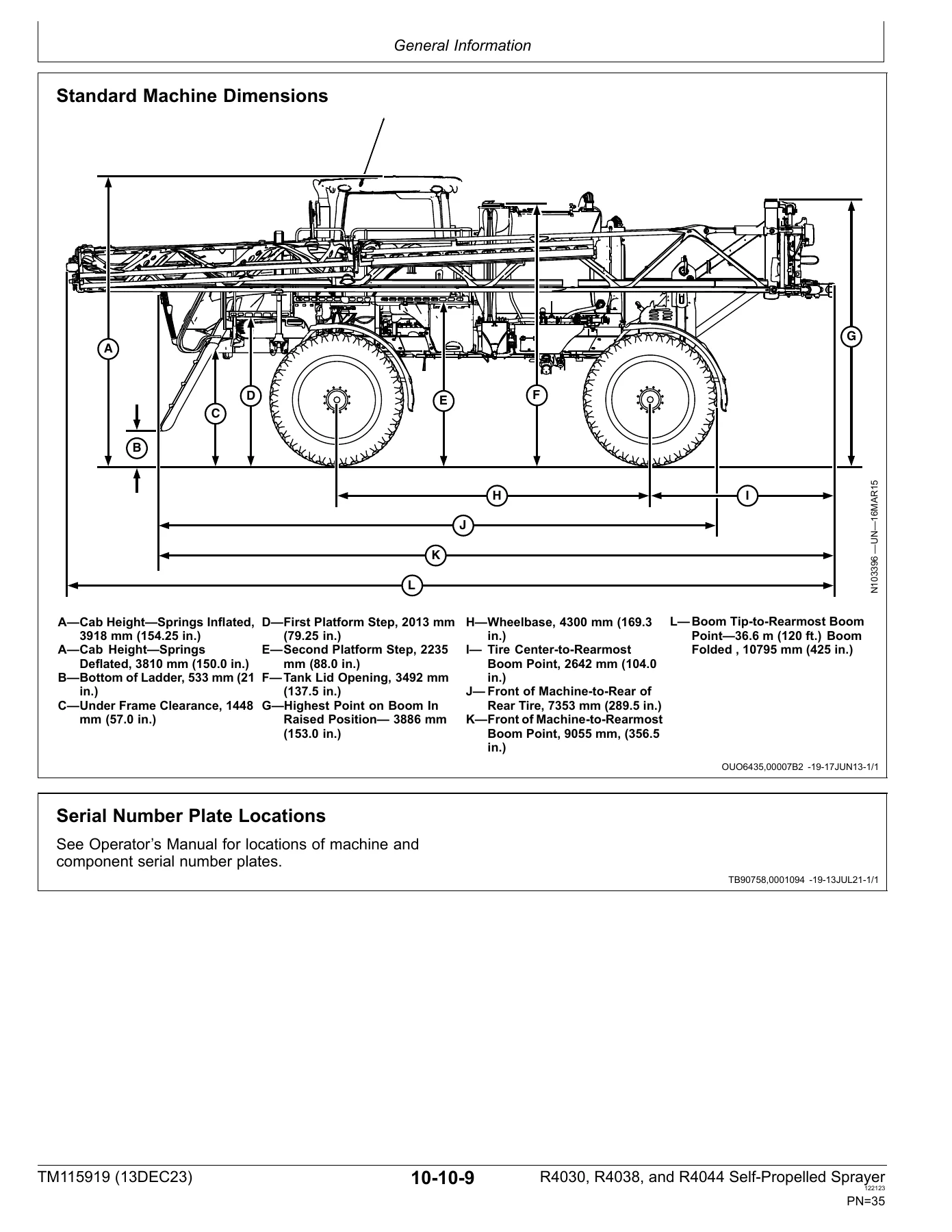
The manual identifies the different powerplants used in the covered machines: the R4030 is listed with a John Deere PowerTech PSS 6.8 L inline six-cylinder diesel, while the R4038 and R4044 use a PowerTech PSS 9.0 L inline six-cylinder diesel. Machine specification pages also document the hydrostatic drive layout, planetary hubs, electrical and hydraulic systems, boom arrangement, steering, fluid capacities, machine weights, spray tank capacities, solution-pump data, cab air conditioning, nozzle configurations, and machine dimensions. These values give technicians a useful baseline before dismantling or checking a system.
Repair procedures are illustrated throughout with component photographs, line drawings, exploded views, numbered parts, tool callouts, tightening sequences, and measured specifications. Examples include engine removal and installation with or without the oil pan, selective catalytic reduction and exhaust component work, alternator and starting-circuit work, hydrostatic drive and planetary hub repair, steering and brake repairs, tread-adjust and suspension work, hydraulic pump and valve repair, solution-pump and nozzle repair, cab and seat work, and steel or carbon-fiber boom service. Several procedures are divided by serial-number breakpoints where the machine configuration changed, so matching the procedure to the machine is important.
Chapters Covered
Section 10—General Information
- Group 05—Safety
- Group 10—General Information
- Group 15—Tune-Up and Adjustment
- Group 20—Fuel and Lubricants
Section 20—Engine
- Group 00—Component Removal and Installation
Section 30—Fuel, Air Intake, and Cooling Systems
- Group 00—Component Removal and Installation
- Group 05—Diesel Fuel System
- Group 10—Engine Cooling System
Section 40—Electrical
- Group 05—Batteries
- Group 10—Connector Repair
- Group 15—Charging Circuit
- Group 20—Starting Circuit
- Group 25—Fuses and Relays
- Group 30—Lighting
- Group 35—Chassis Control System
- Group 40—Engine Control System
- Group 45—Spray Rate Control System
- Group 50—Boom Control System
- Group 55—Cab Components
- Group 60—Wiring Harness Routing
Section 50—Power Train Repair
- Group 00—Remove and Install Hydrostatic Components
- Group 05—Hydrostatic Drive Repair
- Group 10—Planetary Hub Repair
Section 60—Steering and Brakes
- Group 00—Component Removal and Installation
- Group 05—Steering
- Group 10—Brakes
Section 61—Suspension and Tread Adjust Repair
- Group 00—Component Removal and Installation
- Group 05—Tread Adjust Cylinders
- Group 10—Suspension
Section 70—Hydraulic System
- Group 00—Component Removal and Installation
- Group 05—Hydraulic Pump
- Group 10—Hydraulic Valves
- Group 15—Hydraulic Cylinders
- Group 20—Hydraulic Reservoir
- Group 25—Accumulator
Section 80—Solution Spray System
- Group 00—Component Removal and Installation
- Group 05—Nozzle Repair
- Group 10—Solution Tank
- Group 15—Solution Pump—Standard
- Group 16—Solution Pump—High Flow (S.N. —190000)
- Group 17—Solution Pump—High Flow (S.N. 190001—)
- Group 20—Control Valves
- Group 25—Rinse Tank
- Group 30—Eductor
- Group 35—Direct Injection
- Group 40—Flow Meter
Section 81—Foam Marker and On Board Air System
- Group 00—Component Removal and Installation
- Group 05—Foam Marker System Repair
Section 82—Dry Spreader and Solution System Conversion
- Group 05—Dry Spreader and Solution System
Section 90—Operator Station
- Group 00—Component Removal and Installation
- Group 05—Heating, Ventilating, and Air Conditioning (HVAC)
- Group 10—Air Conditioning System
- Group 15—Cab Door
- Group 20—Ultimate Seat Top
- Group 25—ActiveSeat II Suspension
Section 100—Boom
- Group 00—Center Frame
- Group 10—Steel Boom
- Group 15—Carbon Fiber Boom
Section 199—Dealer Fabricated Tools
- Group 05—Dealer Fabricated Tools
Taken together, these chapters let a technician work from general machine data into the specific repair area without losing the model context. The same manual brings together mechanical, electrical, hydraulic, spray-system, operator-station, and boom repair information, which is valuable when a job crosses system boundaries—for example, when a boom problem involves hydraulic cylinders, electrical controls, spray plumbing, and structural hardware.
Specifications, Torque Data, and Serial-Number Variations
TM115919 contains extensive specification blocks at the beginning of repair groups and beside individual procedures. The manual includes general metric and unified-inch fastener torque charts, face-seal and O-ring fitting torque tables, flange torque values, component-specific tightening sequences, pressures, capacities, dimensions, and service data. Procedure-specific values are shown directly in the work steps for items such as engine mounts, oil-pan fasteners, exhaust clamps, sensors, driveshaft hardware, hydraulic components, suspension parts, solution pumps, and boom hardware.
Complete PDF Bookmark Tree
Complete Bookmarks
The complete bookmarks in the “John Deere R4030 R4038 R4044 Self-Propelled Sprayer Repair Manual TM115919 – December 2023” are as follows:
+Contentsp. 5
+General Informationp. 8
+Safetyp. 9
Recognize Safety Informationp. 9
Understand Signal Wordsp. 9
Handle Fluids Safely—Avoid Firesp. 9
Prevent Battery Explosionsp. 10
Prepare for Emergenciesp. 10
Handling Batteries Safelyp. 11
Handle Agricultural Chemicals Safelyp. 12
Service and Operate Chemical Sprayers Safelyp. 13
Avoid Contact with Agricultural Chemicalsp. 14
Clean Vehicle of Hazardous Pesticidesp. 14
Park Machine Safelyp. 14
Support Machine Properlyp. 15
Wear Protective Clothingp. 15
Work in Clean Areap. 15
Service Machines Safelyp. 16
Work In Ventilated Areap. 16
Illuminate Work Area Safelyp. 16
Replace Safety Signsp. 17
Use Proper Lifting Equipmentp. 17
Avoid High-Pressure Fluidsp. 17
Wait Before Opening High-Pressure Fuel Systemp. 18
Service Accumulator Systems Safelyp. 18
Remove Paint Before Welding or Heatingp. 18
Avoid Heating Near Pressurized Fluid Linesp. 19
Service Tires Safelyp. 19
Avoid Harmful Asbestos Dustp. 19
Practice Safe Maintenancep. 20
Use Proper Toolsp. 20
Construct Dealer-Made Tools Safelyp. 21
Decommissioning — Proper Recycling and Disposal of Fluids and Componentsp. 21
Servicing Electronic Control Unitsp. 22
Welding Near Electronic Control Unitsp. 22
Keep Electronic Control Unit Connectors Cleanp. 22
Precautions for Weldingp. 23
Clean Exhaust Filter Safelyp. 24
Protect Against High Pressure Sprayp. 25
Live With Safetyp. 25
+General Informationp. 27
Machine Specificationp. 27
Dimensions—All Machinesp. 34
Standard Machine Dimensionsp. 35
Serial Number Plate Locationsp. 35
Sealants and Adhesives Cross-Reference Chartp. 36
Face Seal Fittings Assembly and Installation—All Pressure Applicationsp. 37
Metric Face Seal and O-Ring Stud End Fitting Torque Chart—Standard Pressuresp. 38
Metric Face Seal and O-Ring Stud End Fitting Torque Chart—High-Pressure Applicationsp. 39
SAE Face Seal and O-Ring Stud End Fitting Torque Chart—Standard Pressuresp. 40
SAE Face Seal and O-Ring Stud End Fitting Torque Chart—High Pressure Applicationsp. 41
Four Bolt Flange Fittings Assembly and Installation—All Pressure Applicationsp. 42
SAE Four Bolt Flange Cap Screw Torque Values—Standard Pressure Applicationsp. 42
SAE Four Bolt Flange Cap Screw Torque Values—High Pressure Applicationsp. 43
External Hexagon Port Plug Torque Chartp. 43
Metric Bolt and Screw Torque Valuesp. 44
Unified Inch Bolt and Screw Torque Valuesp. 45
Programming Control Unitsp. 46
Servicing and Connecting Snap to Connect STC Fittingsp. 47
+Tune-Up and Adjustmentp. 49
Tune-Up and Adjustmentp. 49
Care and Maintenance of Beltsp. 50
Defective Beltsp. 51
Generation 4 and G5 Displaysp. 52
+Fuel and Lubricantsp. 53
Essential or Recommended Toolsp. 53
Diesel Fuelp. 54
Lubricity of Diesel Fuelp. 55
Diesel Engine Coolant (Engine with Wet Sleeve Cylinder Liners)p. 56
Operating in Warm Temperature Climatesp. 57
John Deere Cool-Gard II Coolant Extenderp. 57
Water Quality for Mixing with Coolant Concentratep. 58
Testing Coolant Freeze Pointp. 59
Required Emission-Related Informationp. 59
Diesel Exhaust Fluid (DEF) — Use in Selective Catalytic Reduction (SCR) Equipped Enginesp. 60
Storing Diesel Exhaust Fluid (DEF)p. 60
Testing Diesel Exhaust Fluid (DEF)p. 61
Disposal of Diesel Exhaust Fluid (DEF)p. 61
Greasep. 61
Hydrostatic/Hydraulic Drive Oilp. 62
Suspension and Steering Greasep. 62
Planetary Hub Oilp. 62
Diesel Engine Break-In Oil — Non-Emissions Certified and Certified Tier 1, Tier 2, Tier 3, Stage I, Stage II, and Stage IIIp. 63
Diesel Engine Oil — Tier 2 and Stage IIp. 64
John Deere Break-In Plus Engine Oil — Interim Tier 4, Final Tier 4, Stage IIIB, Stage IV, and Stage Vp. 64
Diesel Engine Oil — Interim Tier 4, Final Tier 4, Stage IIIB, Stage IV, and Stage Vp. 65
+Enginep. 67
+Component Removal and Installationp. 69
Essential or Recommended Toolsp. 69
Other Materialp. 69
Specificationsp. 70
John Deere Engine Repair—Use CTMp. 73
Remove and Install Engine without Oil Pan (R4038 and R4044)p. 74
Remove and Install Engine with Oil Pan (R4038 and R4044)p. 85
Remove and Install Engine without Oil Pan (R4030)p. 99
Remove and Install Engine with Oil Pan (R4030)p. 109
Install Timing Gear Coverp. 125
Position Hood Forwardp. 127
Remove and Install Hoodp. 127
Remove and Install Selective Catalytic Reduction (SCR)p. 129
Remove and Install Exhaust Pipes and Filter—Tier 4/Stage IVp. 133
Remove and Install Exhaust Pipes and Muffler—Tier 2/Stage IIp. 142
Remove and Install Auxiliary Drive Beltp. 144
Inspect Belt Tensionerp. 146
Auxiliary Drive Belt Routingp. 147
Remove and Install Driveshaft (S.N. —209999)p. 147
Remove and Install Driveshaft (S.N. 210000—)p. 150
Inspect Drive Shaftp. 153
+Fuel, Air Intake, and Cooling Systemsp. 155
+Component Removal and Installationp. 157
Specificationsp. 157
Remove and Install Fuel Tankp. 158
Remove and Install Fuel Level Sensorp. 160
Remove and Install Diesel Exhaust Fluid (DEF) Tank—Style Ap. 161
Remove and Install Diesel Exhaust Fluid (DEF) Tank—Style Bp. 163
Remove and Install Diesel Exhaust Fluid (DEF) Tank Header—Style Ap. 165
Remove and Install Diesel Exhaust Fluid (DEF) Tank Header—Style Bp. 166
Remove and Install Diesel Exhaust Fluid (DEF) Injection Pumpp. 167
Remove and Install Cooling Packagep. 168
Remove and Install Radiatorp. 173
Remove and Install Charge Air Coolerp. 176
Remove and Install Fan Beltp. 177
Remove and Install Hydraulic Oil Coolerp. 178
Remove and Install Fuel Coolerp. 178
Remove and Install Air Conditioning Condenserp. 179
Remove and Install Viscous Fan Drivep. 180
+Diesel Fuel Systemp. 183
Specificationsp. 183
Clean and Inspect Fuel Tankp. 183
Replace Fuel Filter, Electric Fuel Pump, and Bleed Fuel Systemp. 183
Turbocharger Repair—Use CTMp. 183
DEF Tank Exploded View—Style Ap. 184
DEF Tank Exploded View—Style Bp. 185
+Engine Cooling Systemp. 187
Essential or Recommended Toolsp. 187
Specificationsp. 187
Drain, Flush, and Fill Cooling System (R4030)p. 187
Drain, Flush, and Fill Cooling System (R4038 and R4044)p. 191
Test Radiator, Deaeration Tank, and Overflow Tankp. 195
Test Deaeration Tank Cap and Overflow Tank Capp. 195
+Electricalp. 199
+Batteriesp. 201
Essential or Recommended Toolsp. 201
Battery Safetyp. 201
Prevent Damage to Electrical Systemsp. 202
Checking Electrolyte Specific Gravityp. 202
Battery Replacementp. 203
Charging Batteriesp. 204
Connecting Battery Cablesp. 205
+Connector Repairp. 207
Using High-Pressure Washersp. 207
ExactApply and ExactRate Harness Repair Procedurep. 207
Connector Repair—Use CTMp. 210
+Charging Circuitp. 211
Specificationsp. 211
Remove and Install Alternatorp. 211
+Starting Circuitp. 213
Specificationsp. 213
Remove and Install Starter Motorp. 213
Remove and Install Starter Circuit Relayp. 214
+Fuses and Relaysp. 215
Cab Load Center Fuses and Relaysp. 215
Front Chassis Load Centerp. 217
Rear Chassis Load Centerp. 218
Vehicle Electrification Center (VEC)p. 219
Battery Box Fuses and Relayp. 221
See & Spray Premium Load Centerp. 221
+Lightingp. 223
Safety Rules When Replacing Halogen Bulbsp. 223
Replace and Adjust Field Lightsp. 223
Hood Head Light Bulb Replacement and Adjustmentp. 223
+Chassis Control Systemp. 225
Specificationsp. 225
Remove and Install Hydraulic Oil Temperature Sensor and Oil Level Sensorp. 226
Remove and Install AutoTrac Control Unitp. 227
Remove and Install Chassis Control Unit (CCU)p. 228
Remove and Install Wheel Speed Sensor—R4030 (S.N. —192000)p. 228
Remove and Install Wheel Speed Sensor—R4030 (S.N. 192001—)p. 229
Remove and Install Wheel Speed Sensor—R4038 (S.N. —194000)p. 229
Remove and Install Wheel Speed Sensor—R4038 and R4044 (S.N. 194001—)p. 230
Remove and Install Wheel Angle Sensorp. 230
Remove and Install Tread Adjust Sensorp. 231
+Engine Control Systemp. 233
Engine Sensor and Switchesp. 233
+Spray Rate Control Systemp. 235
Other Materialp. 235
Specificationsp. 235
Remove and Install Spray Rate Control Unit (SRC)p. 235
Remove and Install Spray Rate Control Unit (SRC) with ExactApplyp. 236
Remove and Install Master Nozzle Control Unit (MNC)p. 237
Remove and Install Nozzle Command Controller (NCC)p. 238
Remove and Install Key FOB Receiverp. 239
Remove and Install Solution Pressure Sensorp. 240
Remove and Install Flowmeter Sensorp. 240
Remove & Install See & Spray Premium Camerasp. 241
Remove and Install Vision Processing Unit (VPU)p. 242
Remove and Install Gateway Controller (GWC)p. 242
Remove and Install See & Spray Premium Ethernet Switchp. 243
+Boom Control Systemp. 245
Remove and Install Boom Height Control Unit (BHC)p. 245
Remove and Install Boom Height Control Unit (BHC) with ExactApplyp. 246
Remove and Install BoomTrac Pro Sensorp. 247
Remove and Install BoomTrac Pro 2.0 Sensorp. 248
Remove and Install BoomTrac Pro Roll Sensorp. 248
Remove and Install Boom Height Sensorp. 249
Remove and Install BoomTrac Pro 2.0 Inertia Measurement Unit (IMU)—See & Spray Premiump. 250
Remove and Install Boom Tilt Sensorp. 251
Remove and Install Boom Inner Fold Sensor—Steel Boomp. 251
Remove and Install Boom Outer Wing Position Sensor—Steel Boomp. 252
Remove and Install Boom Fold Sensors—Carbon Fiber Boomp. 253
+Cab Componentsp. 255
Other Materialp. 255
Specificationsp. 255
Remove and Install Dome Light Switchp. 255
Remove and Install Cab Door Light Switchp. 256
Remove and Install Ignition Switch (S.N. —6000)p. 256
Remove and Install Ignition Switch (S.N. 6001—)p. 257
Remove and Install Ether Aid Switch (S.N. —6000)p. 260
Remove and Install Ether Aid Switch (S.N. 6001—)p. 261
Remove and Install Air Conditioner Blower Motor Resistorp. 264
Remove and Install Air Conditioner Blower Motor Speed Control—(S.N. 180001—)p. 264
Remove and Install Air Conditioner Deicing Switchp. 265
Remove and Install Case/Duct Temperature Sensor—(S.N. 180001—)p. 265
Remove and Install Air Conditioner Dual Pressure Switchp. 265
Remove and Install Boom Fold/Level Switchp. 266
Remove and Install Turn Signal Indicator Lightingp. 267
Remove and Install Steering Column Mini-Pod (S.N. —6000)p. 268
Remove and Install Steering Column Mini-Pod (S.N. 6001—)p. 270
Remove and Install Rotary Light Switchp. 273
Remove and Install Rotary Wiper Switchp. 274
Remove and Install Mini-Pod Backlightp. 275
Remove and Install Turn Signal-Horn Switchp. 276
Remove and Install Steering Input Device Sensor (S.N —6000)p. 277
Remove and Install Steering Input Device Sensor (S.N. 6001—)p. 279
Remove and Install Accessory Outlets (S.N. —6000)p. 283
Remove and Install Accessory Outlets (S.N. 6001—)p. 286
Remove and Install Auxiliary Power Stripp. 290
Remove and Install Circulation Blower Motorp. 291
Remove and Install Air Quality (AQS) Pressurizer Blower Motorp. 291
Remove and Install Wiper Motorp. 293
Remove and Install Radio and Speakersp. 294
Remove and Install Corner Post Display—(S.N.—180000)p. 298
Remove and Install Corner Post Display—(S.N. 180001—)p. 298
Remove and Install Hands Free Microphone—(S.N. 180001—)p. 299
Remove and Install Armrest Console Switch Panel—(S.N.—180000)p. 300
Remove and Install Armrest Console—(S.N. —209999)p. 302
Remove and Install Armrest Console—(S.N. 210000—)p. 302
Remove and Install Armrest Control Cover (S.N. —6000)p. 303
Remove and Install Armrest Control Cover—(S.N. 180001—)p. 304
Remove and Install Side Consolep. 305
Remove and Install Armrest Display Unit (S.N. —6000)p. 305
Remove and Install Armrest Display Unit—(S.N. 180001—)p. 306
Remove and Install Navigation Bar Assembly—(S.N. 180001—)p. 306
Remove and Install Multi-Function Lever—(S.N.—180000)p. 307
Remove and Install Multi-Function Lever—(S.N. 180001—)p. 307
Remove and Install Multi-Function Lever Position Switches—(S.N.—180000)p. 308
Remove and Install Multi-Function Lever Position Sensor—(S.N.—180000)p. 309
Remove and Install Multi-Function Lever Position Assembly—(S.N. 180001—)p. 310
Remove and Install Armrest Console Control Module—(S.N. 180001—)p. 310
Remove and Install Armrest Console Auxiliary Power Outlet—(S.N. 180001—)p. 311
Remove an Install Armrest Console USB Ports—(S.N. 180001—)p. 311
Remove and Install Secondary Brake Switch—(S.N. 180001—)p. 312
Remove and Install SCM Module—(S.N. 180001—)p. 313
Remove and Install House Control Module—(S.N. 180001—)p. 314
Remove and Install DCM Module—(S.N. 180001—)p. 315
Remove and Install Spray Nozzle Encoders Module—(S.N. 180001—)p. 315
Remove and Install Spray Nozzle Encoders Backlight—(S.N. 180001—)p. 316
Remove and Install Engagement Switch Backlight—(S.N. 180001—)p. 317
Remove and Install Secondary Handbrake Switch—(S.N.—180000)p. 318
Remove and Install Rate Selector Potentiometer—(S.N.—180000)p. 319
Remove and Install Roof Control Unitp. 320
Remove and Install Modular Telematics Gateway (MTG) Control Unit (S.N. —6000)p. 320
Remove and Install Modular Telematics Gateway (MTG) Control Unit (S.N. 6001—)p. 321
Remove and Install Right-Hand Consolep. 322
Remove and Install 4600 Processorp. 324
Remove and Install Cab Control Unitp. 324
Remove and Install JDLink Antenna (S.N. —6000)p. 325
Remove and Install JDLink Antenna (S.N. 6001—)p. 327
Replace Seat Height Switch—Ultimate Seatp. 330
Replace Seat Ride Firmness Switch—Ultimate Seatp. 331
Replace Seat Vent/Heat Switch—Ultimate Seatp. 332
Replace Seat Vent/Heat Intensity Switch—Ultimate Seatp. 333
Replace Seat Cushion Length Switch—Ultimate Seatp. 334
Replace Seat Lumbar Extension Switch—Ultimate Seatp. 335
Replace Seat Massage Switch—Ultimate Seatp. 336
Replace Seat Back Bolsters Switch—Ultimate Seatp. 337
Remove and Install LIN Control Box—Ultimate Seatp. 338
Remove and Install Seat Position Sensor—ActiveSeat II Suspensionp. 338
+Wiring Harness Routingp. 341
Engine Harness Routingp. 341
Solution System Harness Routingp. 342
Solution Skid with ExactApply Harness Routingp. 343
Solution System with ExactApply Harness Routingp. 344
Chassis Harness Routingp. 347
Cab Harness Routingp. 350
Direct Injection Harness Routingp. 351
Boom Center Frame Harness Routingp. 352
Boom Center Frame with ExactApply Harness Routingp. 353
Boom Wiring Harnessp. 355
Carbon Fiber Boom with ExactApply—36.6 m (120 ft) Wiring Harnessp. 357
Carbon Fiber Boom with ExactApply—40.2 m (132 ft) Wiring Harnessp. 361
Guidance Harness Routingp. 365
+Power Train Repairp. 368
+Remove and Install Hydrostatic Componentsp. 369
Essential or Recommended Toolsp. 369
Service Equipment and Toolsp. 369
Other Materialp. 369
Specificationsp. 370
Replacing Wheel Hardwarep. 372
Tightening Wheel Hardwarep. 372
Remove and Install Drive Tirep. 373
Remove and Install Fenderp. 374
Remove and Install Hydrostatic Drive Pumps (S.N. —209999)p. 375
Remove and Install Hydrostatic Drive Pump (S.N. 210000—)p. 382
Remove and Install Hydrostatic Pump Manifolds (S.N. 210000—)p. 388
Remove and Install Hydrostatic Drive Motor—R4030 (S.N. —192000)p. 390
Remove and Install Hydrostatic Drive Motor—R4030 (S.N. 192001—)p. 392
Remove and Install Hydrostatic Drive Motor—R4038 (S.N. —194000)p. 394
Remove and Install Hydrostatic Drive Motor—R4038 and R4044 (S.N. 194001—)p. 396
Remove and Install Planetary Hubp. 398
Remove, Install, and Adjust Hydrostatic Control Cable (S.N. —209999)p. 400
Remove, Install, and Adjust Hydrostatic Control Linkage (S.N. —209999)p. 404
Drain and Fill Planetary Hubp. 405
+Hydrostatic Drive Repairp. 407
Essential or Recommended Toolsp. 407
Service Equipment and Toolsp. 407
Other Materialp. 407
Specificationsp. 408
Emergency Tow Procedurep. 410
Start-Up Procedure After Hydrostatic Repairp. 412
Flushing Hydrostatic Drive Systemp. 413
Replace Hydrostatic Drive Motor Shaft Sealp. 414
Remove and Install Hydrostatic Pump Side Cover Nutsp. 416
Remove and Install Wheel Motor Control Valve—R4030 (S.N. —192000)p. 416
Disassemble and Assemble Hydrostatic Drive Motor—R4030 (S.N. —192000)p. 419
Remove and Install Wheel Motor Control Valve—R4038 (S.N. —194000)p. 421
Disassemble and Assemble Hydrostatic Drive Motor—R4038 (S.N. —194000)p. 424
Hydrostatic Drive Motor Exploded Viewp. 426
Disassemble and Assemble Hydrostatic Drive Motor Proportional Control Module—R4030 (S.N. 192001—)p. 429
Disassemble and Assemble Hydrostatic Drive Motor—R4030 (S.N. 192001—)p. 431
Disassemble and Assemble Hydrostatic Drive Motor Proportional Control Module—R4038 and R4044 (S.N. 194001—)p. 439
Disassemble and Assemble Hydrostatic Drive Motor—R4038 and R4044 (S.N. 194001—)p. 441
Disassemble and Assemble Hydrostatic Drive Motor Port Platep. 449
Remove and Install Hydrostatic Pump Shaft Seal (S.N. —209999)p. 450
Replace Broken Input Shaft on Hydrostatic Drive Pump (S.N. —209999)p. 453
Remove and Install Hydrostatic Pump Shaft Seal (S.N. 210000—)p. 455
Remove and Install Hydrostatic Pump Input Shaft (S.N. 210000—)p. 458
Replace Hydrostatic Pump Cartridge Valvesp. 460
Replace Hydrostatic Pump Charge Pressure Relief Valvep. 461
Repair Charge Pumpp. 461
Remove and Install Hydrostatic Pump Control Valve (S.N. —209999)p. 464
Remove, Repair, and Install Hydrostatic Pump Control Module (S.N. 210000—)p. 466
Remove and Install Control Valve Neutral Start Switchp. 471
Adjust Neutral Start Switchp. 472
Adjust Control Valve Eccentric Plugp. 472
Flush Procedure for Failed Wheel Motorp. 474
+Planetary Hub Repairp. 475
Essential or Recommended Toolsp. 475
Other Materialp. 477
Specificationsp. 478
Disassemble Planetary Hub—R4030p. 479
Assemble Planetary Hub—R4030p. 490
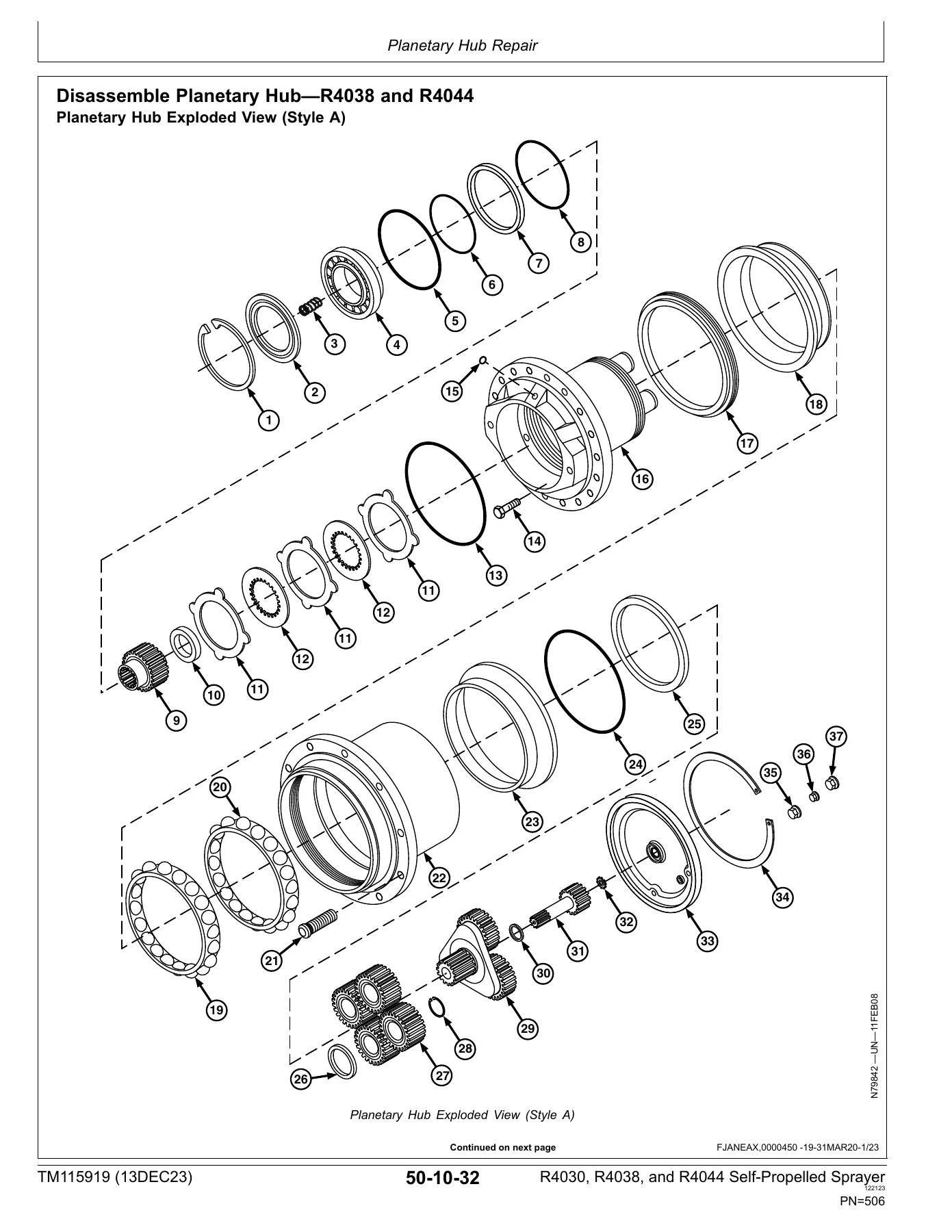
Disassemble Planetary Hub—R4038 and R4044p. 506
Assemble Planetary Hub—R4038 and R4044p. 520
+Steering and Brakesp. 539
+Component Removal and Installationp. 541
Essential or Recommended Toolsp. 541
Other Materialp. 541
Specificationsp. 542
Remove and Install Steering Valvep. 543
Remove and Install Steering Cylinderp. 547
Remove and Install Steering Armp. 548
Remove and Install Toe Control Valvep. 549
Remove and Install Service Brake Valvep. 550
Remove and Install Brake Rotorp. 552
Remove and Install Service Brake Caliperp. 553
Remove and Install AutoTrac Valvep. 554
Remove and Install Secondary Steering Pumpp. 555
+Steeringp. 557
Specificationsp. 557
Disassemble and Assemble Steering Column (S.N. —6000)p. 557
Disassemble and Assemble Steering Column (S.N. 6001—)p. 561
Bleed Steering Systemp. 567
Check Front Axle Toe-Inp. 567
Adjust Front Axle Toe-Inp. 570
Disassemble and Assemble AutoTrac Valvep. 571
Steering Valve Identificationp. 573
Disassemble and Assemble Steering Valvep. 574
Disassemble and Assemble Secondary Steering Pumpp. 580
+Brakesp. 581
Specificationsp. 581
Inspect Service Brake System Componentsp. 581
Disassemble, Inspect, and Assemble Service Brake Linkage (S.N. —6000)p. 582
Disassemble, Inspect, and Assemble Service Brake Linkage (S.N. 6001—)p. 585
Disassemble and Assemble Service Brake Caliperp. 587
Start-Up Procedure After Brake System Repairp. 588
Repair Park Brakep. 588
+Suspension and Tread Adjust Repairp. 589
+Component Removal and Installationp. 591
Essential or Recommended Toolsp. 591
Other Materialp. 591
Specificationsp. 592
Remove and Install Air Spring Assemblyp. 593
Remove and Install Suspension/Drive Mount Housingp. 594
Remove and Install Air Spring Leveling System Control Valvep. 598
Remove and Install Tread Adjust Cylindersp. 599
Remove and Install Tread Adjust Shim Padsp. 603
+Tread Adjust Cylindersp. 607
Disassemble and Assemble Tread Adjust Cylinderp. 607
+Suspensionp. 609
Essential or Recommended Toolsp. 609
Other Materialp. 611
Specificationsp. 611
Remove and Install Suspension/Drive Mount Housing Seals and Bushingsp. 612
Remove and Install Front Axle Knee Bushingsp. 614
Front Suspension—Exploded Viewp. 618
Remove and Install Front Axle Kneep. 619
Rear Suspension—Exploded Viewp. 624
Remove and Install Rear Axle Kneep. 625
+Hydraulic Systemp. 630
+Component Removal and Installationp. 631
Essential or Recommended Toolsp. 631
Specificationsp. 632
Remove and Install Hydraulic Pump Compensatorp. 635
Remove and Install Hydraulic Pump (S.N. —209999)p. 636
Remove and Install Hydraulic Pump (S.N. 210000—)p. 638
Remove and Install Hydraulic Reservoir (S.N. —209999)p. 641
Remove and Install Hydraulic Reservoir (S.N. 210000—)p. 644
Remove and Install Boom Control Valvep. 648
Remove and Install Full Boom Breakaway Valvep. 651
Remove and Install Combination Valvep. 652
Remove and Install Park Brake/Ladder Valvep. 654
Remove and Install Proportional Valvep. 656
Remove and Install Thermal Bypass Valvep. 658
Remove and Install Boom Lift Accumulatorp. 659
Remove and Install Full Boom Breakaway Accumulatorp. 660
Remove and Install Carbon Fiber Boom Tilt Cylinder Accumulatorp. 661
Remove and Install Carbon Fiber Boom Breakaway Valve Blockp. 662
+Hydraulic Pumpp. 663
Other Materialp. 663
Specificationsp. 663
Relieve Hydraulic System Pressurep. 664
Disassemble and Assemble Hydraulic Pump Compensatorp. 666
Disassemble and Assemble Hydraulic Pumpp. 668
+Hydraulic Valvesp. 675
Other Materialp. 675
Specificationsp. 676
Boom Control Valve General Informationp. 677
Disassemble and Assemble Boom Control Valvep. 678
Disassemble and Assemble Park Brake/Ladder Valvep. 684
Disassemble and Assemble Combination Valvep. 685
Disassemble and Assemble Proportional Valvep. 690
Disassemble and Assemble Full Boom Breakaway Valvep. 692
Disassemble and Assemble Carbon Fiber Boom Breakaway Valve Blockp. 693
Disassemble and Assemble Thermal Bypass Valvep. 695
+Hydraulic Cylindersp. 697
Other Materialp. 697
Specificationsp. 698
Boom Cylinder Orifice Locationsp. 699
Remove and Install Ladder Cylinderp. 700
Disassemble and Assemble Ladder Cylinderp. 701
Remove and Install Boom Lift Cylindersp. 702
Remove and Install Boom Inner Fold Cylindersp. 703
Remove and Install Full Boom Breakaway Cylinderp. 704
Remove and Install Boom Swing Cylinderp. 705
Remove and Install Boom Tilt Cylinders—Steel Boomp. 706
Remove and Install Boom Outer Fold Cylinders—Steel Boomp. 707
Remove and Install Tilt Cylinder—Carbon Fiber Boomp. 708
Remove and Install Boom Inner Fold Cylinder—Carbon Fiber Boomp. 709
Remove and Install Outer Boom Fold Cylinder—Carbon Fiber Boomp. 710
Remove and Install Breakaway Fold Cylinder—Carbon Fiber Boomp. 715
Remove and Install Roll Lock Cylindersp. 718
+Hydraulic Reservoirp. 719
Specificationsp. 719
Clean Hydraulic Reservoir Strainersp. 719
+Accumulatorp. 721
Essential or Recommended Toolsp. 721
Specificationsp. 721
Service Accumulator Systems Safelyp. 722
Relieve Full Boom Breakaway System Pressurep. 722
Service Accumulatorsp. 723
Accumulator Pre-Charge Pressure Correction for Ambient Air Temperaturep. 725
+Solution Spray Systemp. 728
+Component Removal and Installationp. 729
Essential or Recommended Toolsp. 729
Service Equipment and Toolsp. 729
Other Materialp. 729
Specificationsp. 729
Empty Tank and Boom Plumbing—Decontaminate Spray Equipmentp. 730
Service Spray Equipment Safelyp. 730
Remove and Install Solution Tankp. 731
Remove and Install Agitation Nozzlesp. 736
Remove and Install Solution Pump and Motorp. 737
Remove and Install Boom Solution Control Valvesp. 739
Remove and Install Rinse Water Control Valvep. 740
Remove and Install Solution Control Valvesp. 740
Remove and Install Flowmeter Assemblyp. 741
Remove and Install Rinse Tank Assemblyp. 742
Remove and Install Tank Level Sensorp. 744
Remove and Install Target Fill Sensorp. 745
Remove and Install AutoTrac Vision Sensorp. 746
Remove and Install AutoTrac RowSense Sensorp. 746
Remove and Install ExactApply Nozzle Bodyp. 750
Remove and Install Individual Nozzle Control (INC) Nozzle Body (5-Way)p. 750
Remove and Install Individual Nozzle Control Heavy Duty (INC HD) Nozzle Body (5-Way)p. 751
+Nozzle Repairp. 753
Essential or Recommended Toolsp. 753
Other Materialp. 753
Cleaning SPRAY MASTER 5-Position Nozzle Bodiesp. 754
Disassemble and Assemble ExactApply Nozzle Bodyp. 755
Disassemble and Assemble Individual Nozzle Control (INC) Nozzle Body (5-Way)p. 762
Disassemble and Assemble Individual Nozzle Control Heavy Duty (INC HD) Nozzle Body (5-Way)p. 766
+Solution Tankp. 767
Flush Solution Tank and Spray Systemp. 767
Positioning Agitation Nozzlesp. 768
+Solution Pump—Standardp. 769
Other Materialp. 769
Specificationsp. 769
Solution Pump—Standard Exploded Viewp. 769
Disassemble and Assemble Standard Solution Pumpp. 770
+Solution Pump—High Flow (S.N. —190000)p. 775
Other Materialp. 775
Specificationsp. 775
Solution Pump—High Flow Exploded View (S.N. —190000)p. 776
Disassemble and Assemble High Flow Solution Pump (S.N. —190000)p. 777
+Solution Pump—High Flow (S.N. 190001—)p. 781
Other Materialp. 781
Specificationsp. 781
Solution Pump—High Flow Exploded View (S.N. 190001—)p. 782
Disassemble and Assemble High Flow Solution Pump (S.N. 190001—)p. 783
+Control Valvesp. 793
Other Materialp. 793
Specificationsp. 793
Disassemble and Assemble Fittingsp. 793
Repair Check Valves and Strainersp. 794
Diagnose and Repair Boom Solution Control Valvesp. 794
Diagnose and Repair Solution and Rinse Water Control Valvesp. 795
Disassemble and Assemble Solution and Rinse Water Control Valvesp. 796
Disassemble and Assemble Boom Solution Control Valvesp. 798
+Rinse Tankp. 801
Repair Polyethylene Plasticp. 801
+Eductorp. 806
Eductor Assemblyp. 806
Remove and Install Eductor System Venturip. 807
+Direct Injectionp. 811
Other Materialp. 811
Remove and Install Tank Assemblyp. 811
Remove and Install Mixer Assemblyp. 812
Remove and Install High Volume Pump Assemblyp. 814
Remove and Install Low Volume Pump Assembly—If Equippedp. 815
Remove and Install High Volume Rinse Valvep. 815
Remove and Install Low Volume Rinse Valvep. 818
Disassemble and Assemble Rinse Valvep. 820
+Flow Meterp. 821
Specificationsp. 821
Replace Flowmeter Insertp. 821
Recondition Flowmeterp. 822
Calibrate Flowmeter (S.N. —180000)p. 827
Calibrate Flowmeter (S.N. 180001— )p. 829
+Foam Marker and On Board Air Systemp. 833
+Component Removal and Installationp. 835
Other Materialp. 835
Specificationsp. 835
Remove and Install Foam Marker Concentrate Tankp. 836
Remove and Install Control Box (Single Drop)p. 837
Remove and Install On Board Air Compressorp. 839
Remove and Install On Board Air Dryerp. 843
Remove and Install Foam Mixing Chamberp. 844
+Foam Marker System Repairp. 845
Other Materialp. 845
On Board Air (OBA) Foam Marker Schematicp. 846
Repair Control Box (Single Drop)p. 848
Repair Control Box Solenoidp. 849
Repair Foam Marker Tubesp. 849
Tube Fittingsp. 850
+Dry Spreader and Solution System Conversionp. 851
+Dry Spreader and Solution Systemp. 853
Remove and Install Dry Spreader and Solution Systemp. 853
+Operator Stationp. 856
+Component Removal and Installationp. 857
Essential or Recommended Toolsp. 857
Other Materialp. 857
Specificationsp. 858
Remove and Install Cabp. 860
Repair Cabp. 869
Remove and Install Cab Roofp. 870
Remove and Install Cab Headlinerp. 871
Remove and Install Cab Inner Roofp. 875
Remove and Install Steering Wheelp. 876
Remove and Install Instructional Seat and Lap Beltp. 879
Remove and Install Operator Seat—(S.N.—180000)p. 880
Remove and Install Operator Seat—(S.N. 180001—)p. 881
Remove and Install Operator Presence Switchp. 882
Remove and Install Seat Cushionsp. 883
Remove and Install Seat Angle and Seat Depth Adjuster—(S.N. 180001—)p. 884
Remove and Install Lumbar Support Compressor—(S.N. 180001—)p. 886
Remove and Install Lumbar Support—(S.N. 180001—)p. 886
Remove and Install Lumbar Support Switch—(S.N. 180001—)p. 887
Remove and Install Climate Control Switch—(S.N. 180001—)p. 887
Remove and Install Back Seat Cushion Cooling Blower Unit—(S.N. 180001—)p. 887
Remove and Install Lap Beltp. 888
Remove and Install Left-Hand Armrestp. 889
Remove and Install Operator Seat Fore/Aft Rail Assembly—(S.N. 180001—)p. 889
Remove and Install Operator Seat Sideway Lock Assembly—(S.N. 180001—)p. 890
Remove and Install Operator Seat Sideway Damper Shocks—(S.N. 180001—)p. 890
Remove and Install Operator Air Seat Suspensionp. 891
Remove and Install Operator Seat Swivel Locking Mechanism—(S.N. 180001—)p. 891
Remove and Install Seat Suspension Bellowsp. 892
Remove and Install Vertical Shock Absorber Control Cable Handlep. 893
Remove and Install Vertical Shock Absorber Control Cablep. 893
Remove and Install Vertical Shock Absorberp. 895
Remove and Install Horizontal Shock Absorberp. 897
Remove and Install Fore/Aft Isolator Handlep. 899
Remove and Install Fore/Aft Isolator Locking Mechanismp. 900
Remove and Install Fore/Aft Isolator Assemblyp. 901
Remove and Install Seat Suspension Compressorp. 904
Remove and Install Seat Level Indicatorp. 906
Remove and Install Seat Suspension Air Springp. 907
Remove and Install Seat Air Reservoir —(S.N.—180000)p. 909
Remove and Install Seat Height Controlp. 910
Remove and Install Upper Seat Suspension Framep. 912
Remove and Install Lower Seat Suspension Framep. 914
Remove, Adjust, and Install Cab Door Latchp. 915
Remove and Install Windshield Glass or Side Windowp. 917
Remove and Install Door Cylinderp. 918
Remove and Install Air Conditioning Compressorp. 919
Remove and Install Receiver-Drierp. 921
Remove and Install Expansion Valvep. 921
Remove and Install HVAC Modulep. 922
Remove and Install Heater Control Valve (Without ClimaTrak)p. 923
Remove and Install Heater Control Valve (With ClimaTrak)p. 924
Remove and Install Mode Control Cablep. 924
Remove and Install Ladderp. 925
Remove and Install Ladder Cylinderp. 927
+Heating, Ventilating, and Air Conditioning (HVAC)p. 929
Heater Line Routingp. 929
Leak Test Manual Heater Control Valvep. 930
+Air Conditioning Systemp. 931
Essential or Recommended Toolsp. 931
Other Materialp. 932
Specificationsp. 933
Hose and Tubing O-Ring Connection Torquesp. 933
Add Refrigerant Oil to Systemp. 933
Add Refrigerant Oil to Pressurized Systemp. 934
System Informationp. 935
Refrigerant Oil Informationp. 936
Charge Air Conditioning Systemp. 936
Check Refrigerant Oil Chargep. 937
Determine Correct Refrigerant Oil Chargep. 938
Discharge Air Conditioning Systemp. 939
Evacuate Air Conditioning Systemp. 940
Flush Air Conditioning Systemp. 941
Leak Test with Dyep. 943
Purge Air Conditioning Systemp. 943
Test Volumetric Efficiencyp. 944
Leak Test Air Quality System Modulep. 945
+Cab Doorp. 947
Specificationsp. 947
Cab Door Adjustment—Step 1p. 947
Cab Door Adjustment—Step 2p. 948
Cab Door Adjustment—Step 3p. 949
Cab Door Adjustment—Step 4p. 950
+Ultimate Seat Topp. 951
Other Materialp. 951
Specificationsp. 951
Remove and Install Seat—Ultimatep. 952
Remove and Install Seat Lever—Ultimatep. 953
Remove and Install Side Panel—Ultimatep. 953
Remove and Install Seat Back Cushion Assembly—Ultimatep. 954
Remove and Install Lumbar System—Ultimatep. 955
Remove and Install Massage Valve Block—Ultimatep. 955
Remove and Install Air Pump—Ultimatep. 956
Remove and Install Seat Back Bolster—Ultimatep. 957
Remove and Install Seat Back Vent Fan—Ultimatep. 957
Remove and Install Seat Back Frame—Ultimatep. 958
Remove and Install Seat Base Cushion Assembly—Ultimatep. 959
Remove and Install Cushion Length Adjustment—Ultimatep. 962
Remove and Install CommandARM Bracket—Ultimatep. 963
Remove and Install Seat Bottom Vent Fan—Ultimatep. 964
Remove and Install Seat Base—Ultimatep. 964
+ActiveSeat II Suspensionp. 967
Other Materialp. 967
Specificationsp. 967
Remove and Install ActiveSeat II Suspensionp. 968
Repair Suspension Topp. 968
Remove and Install Air Spring Reservoirp. 970
Remove and Install Reservoir Attenuation Railp. 972
Remove and Install ActiveSeat II Controllerp. 972
Remove and Install Air Springp. 973
Remove and Install Electric Actuatorp. 976
Remove and Install Seat Compressorp. 978
Repair Suspension Scissor Assemblyp. 979
+Boomp. 983
+Center Framep. 985
Essential or Recommended Toolsp. 985
Other Materialp. 986
Specificationsp. 986
Remove and Install Boom Swing Shock Absorbersp. 987
Remove and Install Boom Swing Linkp. 987
Remove and Install Center Frame Roll Bushingsp. 988
Remove and Install Full Boom Breakaway Rockerp. 990
+Steel Boomp. 991
Essential or Recommended Toolsp. 991
Other Materialp. 994
Specificationsp. 995
Remove and Install Boom Sectionp. 995
Adjust Breakaway Section Springsp. 997
Remove and Install Boom Breakaway Springp. 998
Remove and Install Outer Wing Hinge Bushingsp. 999
Remove and Install Outer Wing Fold Linkage Bushingsp. 1000
Remove and Install Breakaway Spring Link Bushingsp. 1002
Remove and Install Breakaway Fold Linkage Bushingsp. 1004
Align See & Spray Premium Camera Bracketsp. 1007
+Carbon Fiber Boomp. 1011
Other Materialp. 1011
Specificationsp. 1012
Carbon Fiber Boom Terminologyp. 1013
Remove and Install Carbon Fiber Boom Bushingsp. 1014
Remove and Install Inner Boom Sectionp. 1022
Remove and Install Inner Boom Tilt and Strut Bushingsp. 1024
Remove and Install T6/T7 Ropep. 1025
Remove and Install Retraction Linesp. 1026
Remove and Install T1 Link, Compression Post, and T2 Linkp. 1027
Remove and Install Outer Boom Sectionp. 1032
Remove and Install Outer Boom Fold and Fold Cylinder Bushingsp. 1037
Remove and Install Breakaway Fold Link Bushings—36.6 m (120 ft)p. 1038
Remove and Install Breakaway Fold Link Bushings—40.2 m (132 ft)p. 1041
Remove and Install Breakaway Tension Chain—36.6 m (120 ft)p. 1044
Remove and Install Breakaway Tension Chain—40.2 m (132 ft)p. 1048
Boom Alignment Specification Overviewp. 1052
Adjust Outer Wing, T3 Link, and T6/T7 Ropep. 1053
Adjust Breakaway Tensionp. 1057
Adjust Breakaway Tension Chain—36.6 m (120 ft)p. 1058
Adjust Breakaway Tension Chain—40.2 m (132 ft)p. 1060
Adjust Breakaway Alignment—36.6 m (120 ft)p. 1063
Adjust Breakaway Alignment—40.2 m (132 ft)p. 1066
Spray Boom Carbon Fiber Repairp. 1068
Remove and Install Carbon Fiber Boom Outer Breakaway Locking Solenoidp. 1075
Remove and Install Boom Breakaway Lock Bushing-36.6 m (120 ft)p. 1076
+Dealer Fabricated Toolsp. 1079
+Dealer Fabricated Toolsp. 1081
DFNXT7—Agitation Nozzle Toolp. 1081
DFNX65-A1 Eccentric Plug Adjustment Toolp. 1082
DFNX65-A2 Sizing Arborp. 1082
DFN20 Solution Pump Seal Driver—Standard Solution Pumpp. 1083
DFNXT13—Rear Planetary Assembly Spacerp. 1083
DFNXT18—Spindle Driverp. 1083
DFNXT39—Hydrostatic Pump Sheave Removal Toolp. 1084
DFNXT19—Hydrostatic Pump Removal Toolp. 1085
DFNXT42—Jack Extensionp. 1086
DFNXT43—Auxiliary Hydraulic Pump Removal Adapterp. 1088
DFNXT45—Hydrostatic Pump Removal Adapterp. 1089
+Page Numberp. 5
+Section 10p. 8
Group 05p. 9
Group 10p. 27
Group 15p. 49
Group 20p. 53
+Section 20p. 67
+Section 30p. 155
Group 00p. 157
Group 05p. 183
Group 10p. 187
+Section 40p. 199
Group 05p. 201
Group 10p. 207
Group 15p. 211
Group 20p. 213
Group 25p. 215
Group 30p. 223
Group 35p. 225
Group 40p. 233
Group 45p. 235
Group 50p. 245
Group 55p. 255
Group 60p. 341
+Section 50p. 368
Group 00p. 369
Group 05p. 407
Group 10p. 475
+Section 60p. 539
Group 00p. 541
Group 05p. 557
Group 10p. 581
+Section 61p. 589
Group 00p. 591
Group 05p. 607
Group 10p. 609
+Section 70p. 630
Group 00p. 631
Group 05p. 663
Group 10p. 675
Group 15p. 697
Group 20p. 719
Group 25p. 721
+Section 80p. 728
Group 00p. 729
Group 05p. 753
Group 10p. 767
Group 15p. 769
Group 16p. 775
Group 17p. 781
Group 20p. 793
Group 25p. 801
Group 30p. 806
Group 35p. 811
Group 40p. 821
+Section 81p. 833
Group 00p. 835
Group 05p. 845
+Section 82p. 851
+Section 90p. 856
Group 00p. 857
Group 05p. 929
Group 10p. 931
Group 15p. 947
Group 20p. 951
Group 25p. 967
+Section 100p. 983
Group 00p. 985
Group 10p. 991
Group 15p. 1011
+Section 199p. 1079
Configuration changes are also separated where required. Examples visible in this edition include solution-pump coverage split at S.N. —190000 and S.N. 190001—, hydraulic pump and reservoir procedures split at S.N. —209999 and S.N. 210000—, and other repairs that distinguish earlier and later serial-number configurations. This makes the John Deere R4030 R4038 R4044 Self-Propelled Sprayer Repair Manual TM115919 – December 2023 especially useful for confirming which illustrated procedure and specification applies before parts are removed.
Repair Areas in Practical Terms
For engine-area work, the manual documents removal and installation of the engines used in the three sprayer models, including procedures with and without the oil pan, hood and driveshaft work, selective catalytic reduction components, exhaust pipes and filters, auxiliary drive belt routing, and related tightening data. Fuel, air-intake, and cooling sections cover machine-side component access and repair around the fuel tank, fuel system, cooling package, fan drive, hoses, and associated hardware.
The electrical section extends from batteries and connector repair through charging, starting, fuses and relays, lighting, chassis control, engine control, spray-rate control, boom control, cab components, and harness routing. The power-train chapters address hydrostatic component removal, hydrostatic drive repair, and planetary hub work, including detailed exploded-view and assembly information. Steering and brake groups cover steering components, valves and cylinders, service brakes, and park-brake repair, while the suspension section covers air springs, tread-adjust components, axle knees, seals, bushings, and suspension assemblies.
Sprayer-specific systems receive substantial coverage. Hydraulic chapters include pump, compensator, valves, cylinders, reservoir, and accumulators. The solution-spray section covers decontamination and tank removal, nozzle bodies, standard and high-flow solution pumps, control valves, rinse tank, eductor, direct injection, and flow meter. Separate chapters address the foam marker and on-board air system, dry spreader/solution-system conversion, operator-station and HVAC work, and structural service for center frame, steel boom, and carbon-fiber boom assemblies. The final dealer-fabricated-tools section provides dimensions and information for tools referenced in repair work.
Important Scope Note
This machine manual does not replace every component-level technical publication. In several areas, TM115919 directs the technician to the appropriate Component Technical Manual (CTM) for complete internal component repair information, and some diagnostic procedures are referenced to the Diagnostic and Test manual. For example, the engine-repair section states that the appropriate CTM is required in conjunction with this machine manual for complete engine repair information. TM115919 remains the key machine-side repair reference for access, removal, installation, machine specifications, system repair, adjustment, and reassembly around the R4030, R4038, and R4044 sprayer.
Repair with the Correct Machine Reference
The John Deere R4030 R4038 R4044 Self-Propelled Sprayer Repair Manual TM115919 – December 2023 supports major service work across the engine installation, fuel and cooling systems, electrical circuits, hydrostatic power train, planetary hubs, steering and brakes, suspension, hydraulic system, spray system, cab, and boom. Having the machine-specific procedure, tool information, tightening sequence, torque value, pressure, capacity, and serial-number split in front of you helps reduce avoidable rework and makes it easier to return assemblies to the specified condition.
Delivered as an instant PDF after purchase—no shipping and no waiting for a printed book. Open the manual on a computer, tablet, or phone, and print the pages you need for the workshop or field job.

Reviews
There are no reviews yet.