Description
Complete Illustrated Parts Catalog for P&WC JT15D Turbofan Engines
This is the comprehensive Illustrated Parts Catalog for the JT15D series turbofan engines, covering models JT15D-1, -1A, -1B, -4, -4B, and -4D. Manufactured by Pratt & Whitney Canada, this manual (Part No. 3017544) is essential for identifying, requisitioning, and issuing components for maintenance, overhaul, and repair. It is the authoritative source for part numbers, assemblies, and installation details, used in conjunction with the associated maintenance and overhaul manuals.
File Details
- Manual Type: Illustrated Parts Catalog (IPC)
- Document Part No.: 3017544
- Original Issue Date: 06 May 1977
- Latest Revision Included: Revision 61, dated 13 Aug 2018
- Language: English
- Page Count: Over 900 pages
- File Format: PDF
- Engines Covered: JT15D-1, -1A, -1B, -4, -4B, -4D
Chapters & Major Sections Covered
This IPC is organized by ATA chapter and covers the entire engine in detailed breakdowns. The primary chapter sections include:
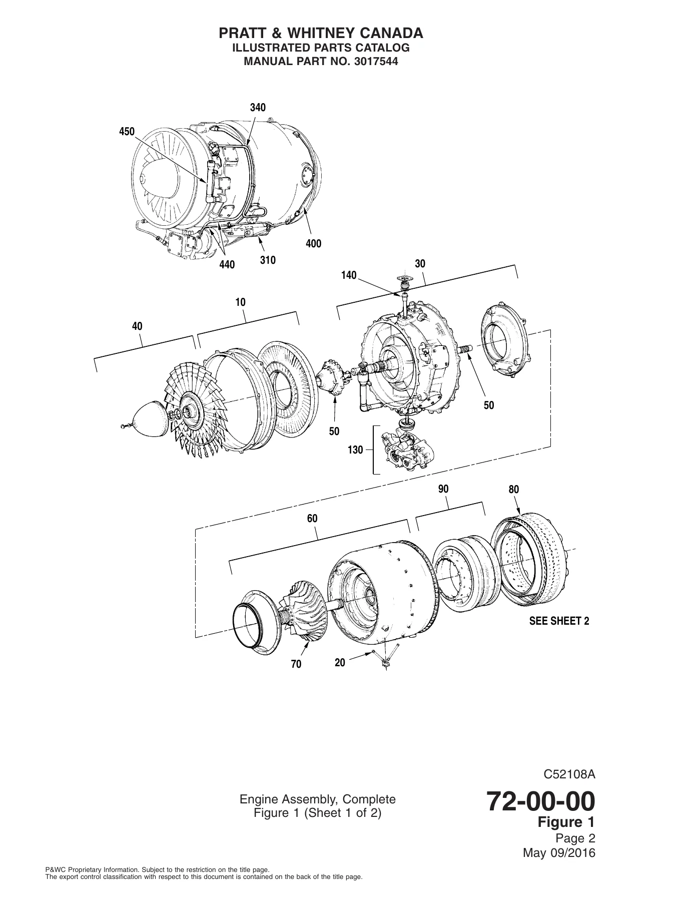
- 72-00 Engine, General: Complete engine assembly views and component location references.
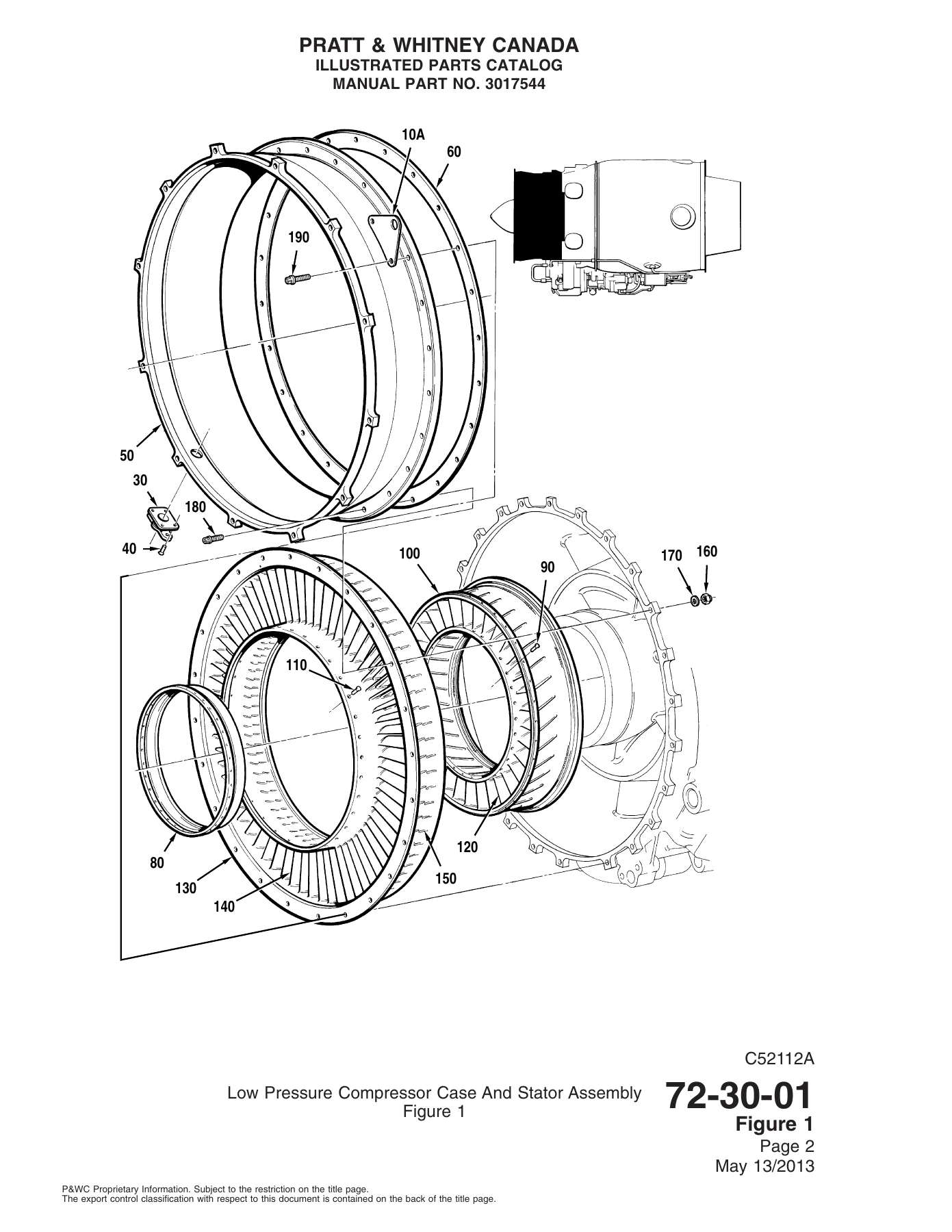
- 72-30 Compressor Section: Low and high-pressure compressor cases, rotors, stators, and No. 1 bearing assembly.
- 72-40 Combustion Section: Combustion chamber liner and low-pressure turbine stator support.
- 72-50 Turbine Section: High and low-pressure turbine stators, disks, rotors, and exhaust duct with No. 4 bearing housing.
- 72-60 Accessory Gearbox: Complete gearbox and drive shaft installation, oil pump, and external covers.
- 72-70 Bypass Section: Front and rear inner bypass ducts and outer bypass duct installation.
- 73-10 Engine Fuel and Control: Fuel pump, flow divider, manifold, flowmeter, and motive flow valve installations.
- 73-20 Fuel Control: Fuel control unit installation.
- 74-10 & 74-20 Ignition System: Ignition exciter, cables, and spark igniter installation.
- 75-00 Air: T1 thermocouple, anti-icing air tube, solenoid valve, and cabin air bleed.
- 77-00 Engine Indicating: T1 and T6 thermocouple wiring harnesses and pressure sensing system.
- 79-20 & 79-30 Oil: Oil filter element, housing, pressure relief valve, check valves, pressure and scavenge oil tubes, and oil filler neck.
This catalog provides a complete part-by-part breakdown of the JT15D engine. It includes detailed illustrations and exploded views of all major assemblies, subassemblies, and individual components. The JT15D Illustrated Parts Catalog is the essential tool for parts identification, ensuring correct part numbers are ordered for any service, repair, or overhaul task. The included Numerical Index allows for quick cross-referencing by part number, making it easy to find the exact component location and associated hardware.
What This Illustrated Parts Catalog Enables You To Do
With this JT15D parts catalog, you can confidently identify every nut, bolt, seal, and rotating assembly on the engine. It provides the exact part numbers required for ordering new components, whether you are performing a hot section inspection, replacing a bearing, or troubleshooting a fuel system issue. This catalog is a critical reference for maintenance planning and ensures you procure the correct, fully interchangeable parts for your specific engine serial number and build specification.
Complete PDF Bookmark Tree
Complete Bookmarks
The complete bookmarks in the “JT15D-1, -1A, -1B, -4, -4B, -4D Turbofan Engine Illustrated Parts Catalog – PDF” are as follows:
+ILLUSTRATED PARTS CATALOG (3017544)p. 1
REVISION TRANSMITTAL SHEETp. 3
RECORD OF REVISIONSp. 4
RECORD OF TEMPORARY REVISIONSp. 6
LIST OF EFFECTIVE PAGESp. 7
SERVICE BULLETIN LISTp. 8
SPARE PARTS BULLETIN LISTp. 18
PARTS DIGEST LISTp. 20
LIST OF CHAPTER/SECTION/SUBJECTSp. 24
TABLE OF CONTENTSp. 27
+INTRODUCTIONp. 28
LIST OF EFFECTIVE PAGESp. 28
TABLE OF CONTENTSp. 29
+INTRODUCTIONp. 31
1. GENERALp. 31
2. ENGINE MODEL DESIGNATIONp. 32
3. EFFECTIVITY AND BUILD SPECIFICATIONp. 32
4. REVISIONSp. 33
5. SERVICE BULLETINS, SPARE PARTS BULLETINS AND PARTS DIGESTSp. 33
6. DETAILED PARTS LISTp. 34
7. PART NUMBERING SYSTEMp. 35
8. ITEM NUMBERSp. 36
9. HOW TO USE THIS CATALOGp. 36
10. CROSS-INDEX SYSTEMSp. 37
11. CATALOG TERMSp. 37
12. ABBREVIATIONp. 42
13. CUSTOMER SERVICEp. 44
14. SUPPLIERS AND SUPPLIER SERVICESp. 45
15. SUPPLIER CODESp. 45
16. APPLICABLE DOCUMENTATIONp. 46
17. NUT OPTIONSp. 51
18. PART SUBSTITUTION LISTp. 52
+NUMERICAL INDEXp. 55
LIST OF EFFECTIVE PAGESp. 55
TABLE OF CONTENTSp. 57
ALPHA INDEXp. 58
NUMERIC INDEXp. 85
+CHAPTER 72 – ENGINEp. 157
+72-00 – ENGINEp. 157
LIST OF EFFECTIVE PAGESp. 157
TABLE OF CONTENTSp. 158
+72-00 – ENGINEp. 159
72-00-00 – FIGURE 1 – ENGINE ASSEMBLY, COMPLETEp. 159
72-00-00 – FIGURE 2 – CONTAINER ASSEMBLY, COMPLETE ENGINE, SHIPPINGp. 178
72-00-00 – SKID BASE ASSEMBLY, CONTAINER SHIPPINGp. 198
+72-30 – COMPRESSOR SECTIONp. 210
LIST OF EFFECTIVE PAGESp. 210
TABLE OF CONTENTSp. 213
+72-30 – COMPRESSOR SECTIONp. 214
72-30-01 – LOW PRESSURE COMPRESSOR CASE AND STATOR ASSEMBLYp. 214
72-30-01 – FIGURE 2 – LOW PRESSURE COMPRESSOR CASE ASSEMBLY AND INSTALLATIONp. 219
72-30-01 – FIGURE 3 – LOW PRESSURE COMPRESSOR STATOR ASSEMBLY AND INSTALLATIONp. 225
72-30-02 – FIGURE 1 – INTERMEDIATE CASING ASSYp. 228
72-30-02 – FIGURE 2 – INTERMEDIATE CASING ASSEMBLYp. 239
72-30-02 – FIGURE 3 – CASE ASSEMBLY, INTERMEDIATE (JT15D-1/-1A/-1B)p. 252
72-30-02 – FIGURE 4 – CASE ASSY, INTERMEDIATE (JT15D-4/-4B/-4D)p. 257
72-30-03 – FIGURE 1 – LOW PRESSURE COMPRESSORp. 264
72-30-03 – FIGURE 2 – LOW PRESSURE COMPRESSOR ROTOR BALANCING ASSEMBLYp. 276
72-30-04 – FIGURE 1 – NO.1 BEARING AND TACHOMETER-GENERATOR DRIVEp. 291
72-30-05 – FIGURE 1 – GAS GENERATOR CASEp. 301
72-30-06 – FIGURE 1 – HIGH PRESSURE COMPRESSOR ROTOR BALANCING ASSEMBLYp. 333
+72-40 – COMBUSTION SECTIONp. 359
LIST OF EFFECTIVE PAGESp. 359
TABLE OF CONTENTSp. 360
+72-40 – COMBUSTION SECTIONp. 361
72-40-01 – COMBUSTION CHAMBER LINER AND LOW PRESSURE TURBINE STATOR SUPPORT ASSEMBLYp. 361
+72-50 – TURBINE SECTIONp. 378
LIST OF EFFECTIVE PAGESp. 378
TABLE OF CONTENTSp. 380
+72-50 – TURBINE SECTIONp. 381
72-50-01 – FIGURE 1 – HIGH PRESSURE TURBINE STATOR, LARGE AND SMALL EXIT DUCTp. 381
72-50-02 – FIGURE 1 – HIGH TURBINE DISK BALANCING ASSEMBLYp. 398
72-50-03 – FIGURE 1 – LOW PRESSURE TURBINE ROTOR BALANCING ASSEMBLYp. 406
72-50-03 – FIGURE 2 – THIRD-STAGE LOW PRESSURE TURBINE DISK BALANCING ASSEMBLYp. 421
72-50-03 – FIGURE 3 – SECOND-STAGE LOW PRESSURE TURBINE DISK BALANCING ASSEMBLYp. 426
72-50-04 – FIGURE 1 – SECOND-STAGE LOW PRESSURE TURBINE STATOR ASSEMBLY, GEOM AREA (Pre-SB7033)p. 430
72-50-04 – FIGURE 2 – SECOND-STAGE LOW PRESSURE TURBINE STATOR ASSY (Post-SB7033)p. 436
72-50-05 – FIGURE 1 – THIRD-STAGE LOW PRESSURE TURBINE STATOR ASSEMBLYp. 449
72-50-05 – FIGURE 2 – THIRD-STAGE LOW PRESSURE TURBINE STATOR ASSEMBLY (POST-SB7054)p. 453
72-50-06 – FIGURE 1 – EXHAUST DUCT AND NO.4 BEARING HOUSING ASSEMBLYp. 459
72-50-06 – FIGURE 2 – REAR EXHAUST DUCT ASSY AND INSTALLATIONp. 486
72-50-06 – FIGURE 3 – EMERGENCY FUEL SHUT-OFF, CONTROL LINKAGE SYSTEMp. 489
+72-60 – ACCESSORY GEARBOXp. 502
LIST OF EFFECTIVE PAGESp. 502
TABLE OF CONTENTSp. 504
+72-60 – ACCESSORY GEARBOXp. 505
72-60-01 – FIGURE 1 – ACCESSORY GEARBOX AND DRIVE SHAFT INSTALLATIONp. 505
72-60-02 – FIGURE 1 – ACCESSORY GEARBOX ASSEMBLY, EXTERNALSp. 512
72-60-02 – FIGURE 2 – ACCESSORY GEARBOX ASSEMBLY, EXTERNALSp. 520
72-60-02 – FIGURE 3 – ACCESSORY GEARBOX ASSEMBLY, INTERNALSp. 528
72-60-02 – FIGURE 4 – PUMP ASSY, OILp. 539
72-60-02 – FIGURE 4A – PUMP ASSEMBLY, OIL, ACCESSORY GEARBOXp. 553
72-60-02 – FIGURE 5 – HOUSING ASSY, ACCESSORY GEARBOXp. 563
72-60-02 – FIGURE 6 – COVER ASSY, ACCESSORY GEARBOXp. 569
72-60-03 – FIGURE 1 – TACHOMETER-GENERATOR DRIVE SHAFT AND COVER INSTALLATIONp. 572
+72-70 – BYPASS SECTIONp. 578
LIST OF EFFECTIVE PAGESp. 578
TABLE OF CONTENTSp. 579
+72-70 – BYPASS SECTIONp. 580
72-70-01 – FIGURE 1 – FRONT INNER BYPASS DUCT INSTALLATIONp. 580
72-70-02 – FIGURE 1 – REAR INNER BYPASS DUCT ASSY AND LIFTING BRACKETp. 585
72-70-02 – FIGURE 2 – REAR INNER BYPASS DUCT ASSEMBLYp. 588
72-70-03 – FIGURE 1 – OUTER BYPASS DUCT INSTALLATIONp. 593
72-70-04 – FIGURE 1 – ENGINE REAR MOUNT INSTALLATIONp. 612
+CHAPTER 73 – ENGINE FUEL AND CONTROLp. 620
+73-10 – ENGINE FUEL AND CONTROLp. 620
LIST OF EFFECTIVE PAGESp. 620
TABLE OF CONTENTSp. 622
+73-10 – ENGINE FUEL AND CONTROLp. 623
73-10-01 – FIGURE 1 – FUEL TO OIL COOLER INSTALLATIONp. 623
73-10-02 – FIGURE 1 – FUEL PUMP INSTALLATIONp. 627
73-10-03 – FIGURE 1 – FUEL PRESSURE TUBES, FLOW DIVIDER VALVE TO MANIFOLDp. 637
73-10-04 – FIGURE 1 – FLOW DIVIDER VALVEp. 643
73-10-05 – FIGURE 1 – FUEL MANIFOLD INSTALLATIONp. 647
73-10-05 – FIGURE 2 – FUEL MANIFOLD INSTALLATION, JT15D-4/-4B/-4Dp. 659
73-10-06 – FIGURE 1 – FUEL DRAIN LINE INSTALLATIONp. 668
73-10-06 – FIGURE 2 – FUEL DRAIN LINE INSTALLATION, TURBINE EXHAUST JT15D-4/-4B (CESSNA)p. 672
73-10-07 – FIGURE 1 – FUEL FLOW METER INSTALLATION (CESSNA AND MITSUBISHI)p. 676
73-10-07 – FIGURE 2 – FUEL FLOWMETER INSTALLATION JT15D-4 (AEROSPATIALE)p. 680
73-10-08 – FIGURE 1 – MOTIVE FLOW VALVE INSTALLATION (CESSNA AND MITSUBISHI)p. 683
73-10-09 – FIGURE 1 – FUEL PRESSURE AND BYPASS TUBES INSTALLATIONp. 690
73-10-10 – FIGURE 1 – PNEUMATIC TUBES, COMPRESSOR DISCHARGE PRESSURE JT15D-1/-1A (CESSNA) AND JT15D-4 (AEROSPATIALE)p. 697
73-10-10 – FIGURE 2 – PNEUMATIC TUBES, COMPRESSOR DISCHARGE PRESSURE, JT15D-1A POST-SB7124, JT15D-4 CESSNA AND MITSUBISHIp. 702
73-10-11 – FIGURE 1 – EMERGENCY FUEL SHUT-OFF SYSTEMp. 709
+73-20 – FUEL CONTROLp. 717
LIST OF EFFECTIVE PAGESp. 717
TABLE OF CONTENTSp. 718
+73-20 – FUEL CONTROLp. 719
73-20-01 – FIGURE 1 – FUEL CONTROL UNIT INSTALLATIONp. 719
+CHAPTER 74 – IGNITIONp. 730
+74-10 – IGNITION SYSTEMp. 730
LIST OF EFFECTIVE PAGESp. 730
TABLE OF CONTENTSp. 731
+74-10 – IGNITION SYSTEMp. 732
74-10-01 – FIGURE 1 – IGNITION EXCITER INSTALLATIONp. 732
74-10-01 – FIGURE 2 – IGNITION EXCITER MOUNT SYSTEM Post-SB7110p. 743
74-10-01 – FIGURE 3 – IGNITION EXCITER MOUNT SYSTEM Pre-SB7111p. 748
+74-20 – IGNITIONp. 758
LIST OF EFFECTIVE PAGESp. 758
TABLE OF CONTENTSp. 759
+74-20 – IGNITIONp. 760
74-20-01 – FIGURE 1 – IGNITION CABLES AND ATTACHING HARDWAREp. 760
74-20-01 – FIGURE 2 – IGNITION LEAD ASSEMBLYp. 774
74-20-02 – FIGURE 1 – SPARK IGNITERS INSTALLATIONp. 778
+CHAPTER 75 – AIRp. 785
+75-00 – AIRp. 785
LIST OF EFFECTIVE PAGESp. 785
TABLE OF CONTENTSp. 786
+75-00 – AIRp. 787
75-00-01 – FIGURE 1 – T1 THERMOCOUPLE ANTI-ICING AIR TUBEp. 787
75-00-01 – FIGURE 2 – T1 THERMOCOUPLE ANTI-ICING AIR TUBE, (JT15D-4 AEROSPATIALE)p. 791
75-00-01 – FIGURE 3 – T1 THERMOCOUPLE ANTI-ICING AIR TUBE (JT15D-4/-4B/-4D CESSNA AND MITSUBISHI)p. 795
75-00-02 – FIGURE 1 – LOW PRESSURE COMPRESSOR ANTI-ICING SOLENOID VALVE AND TUBE INSTALLATIONp. 799
75-00-03 – FIGURE 1 – CABIN AIR BLEED – AIRCRAFT SERVICESp. 807
+CHAPTER 77 – ENGINE INDICATINGp. 812
+77-00 – ENGINE INDICATINGp. 812
LIST OF EFFECTIVE PAGESp. 812
TABLE OF CONTENTSp. 813
+77-00 – ENGINE INDICATINGp. 814
77-00-01 – FIGURE 1 – T1 THERMOCOUPLE WIRING HARNESS INSTALLATION (JT15D-1/-1A/-1B)p. 814
77-00-01 – FIGURE 2 – T1 THERMOCOUPLE WIRING HARNESS INSTALLATION (JT15D-4 AEROSPATIALE)p. 820
77-00-01 – FIGURE 3 – T1 THERMOCOUPLE WIRING HARNESS INSTALLATION (JT15D-4/-4B CESSNA AND JT15D-4/-4D MITSUBISHI)p. 827
77-00-02 – FIGURE 1 – T6 THERMOCOUPLE WIRING HARNESS AND PROBESp. 833
77-00-03 – FIGURE 1 – PRESSURE SENSING SYSTEM INSTALLATIONp. 843
+CHAPTER 79 – OILp. 847
+79-20 – OILp. 847
LIST OF EFFECTIVE PAGESp. 847
TABLE OF CONTENTSp. 848
+79-20 – OILp. 849
79-20-01 – FIGURE 1 – OIL FILTER ELEMENT, HOUSING AND PRESSURE RELIEF VALVE INSTALLATIONp. 849
79-20-01 – FIGURE 2 – HOUSING ASSY, OIL FILTERp. 863
79-20-02 – FIGURE 1 – CHECK VALVE, PRESSURE AND BYPASS OIL TUBES INSTALLATIONp. 869
79-20-03 – FIGURE 1 – PRESSURE OIL TUBES INSTALLATIONp. 877
79-20-04 – FIGURE 1 – SCAVENGE OIL TUBES INSTALLATIONp. 884
+79-30 – OIL INDICATINGp. 892
LIST OF EFFECTIVE PAGESp. 892
TABLE OF CONTENTSp. 893
+79-30 – OIL INDICATINGp. 894
79-30-01 – FIGURE 1 – OIL FILLER NECK AND PLUGS INSTALLATIONp. 894
Why You Need This Manual
Pratt & Whitney Canada’s official Illustrated Parts Catalog is the final authority on part numbers and interchangeability for the JT15D engine series. Using incorrect or superseded part numbers can lead to installation issues, reduced performance, and increased downtime. This manual eliminates guesswork and provides the detailed information required to maintain your engine to OEM standards.
This is a complete PDF download of the official Pratt & Whitney Canada publication. It is a fully digital product that will be available for instant download after purchase. You will receive a searchable PDF that can be viewed on any computer, tablet, or smartphone, and you can print specific pages or the entire manual for use in your workshop.

Reviews
There are no reviews yet.