
Kalmar DRF 400-450 Reachstacker Maintenance Manual PDF
Original price was: $39.95.$24.95Current price is: $24.95.
Kalmar DRF 400-450 Maintenance Manual (UDRF03.01GB) covering preventive maintenance, service schedules, engine, transmission, brakes, load handling, hydraulics, electrics and technical data. Instant PDF download.
Description
The Kalmar DRF 400-450 Maintenance Manual is the service reference written for the Kalmar DRF 400-450 reachstacker, the container-handling machine built by Kalmar Industries AB. Published under document number UDRF03.01GB, it organises the whole machine into function groups and gives the technician the preventive maintenance actions, inspection points, adjustment values and simpler troubleshooting steps needed to keep a DRF 400-450 working reliably. It is a maintenance manual, not a workshop manual: it covers scheduled servicing, checking and adjustment, and fault-finding at system level, while in-depth repair and overhaul procedures sit in the separate Workshop manual.
File Details
- Manual type: Maintenance manual (preventive maintenance and simpler troubleshooting)
- Brand: Kalmar Industries AB
- Machine: Kalmar DRF 400-450 reachstacker
- Document number: UDRF03.01GB
- Language: English
- File format: PDF
- Pages: 362
- Structure: Sections A-C and 0-12, D-G, following the Kalmar function group system
Chapters Covered
- A Foreword – purpose of the manual, reading instructions, function group structure, machine card
- B Safety – service position, depressurising hydraulic and brake systems, oils, fuel system, clothing, working under the machine, lifting heavy components, vibrations, noise, solvents, fire and explosion risks, fluid under pressure, coolant, refrigerant, air pollution, tensioned springs, electric motors, rotating components, tyre system, environment
- C Preventive maintenance – general, work instructions, check and service log, 50h-check, service schedule, lubrication 500 hours, lubrication 1000 hours, washing
- 0 Complete machine – description of the DRF 400-450 reachstacker
- 1 Engine – 1.2 Fuel system, 1.2.3 Fuel pre-filter, 1.2.4 Fuel filter, 1.6 Air intake and exhaust outlet, 1.6.1 Air cleaning system, 1.7 Cooling system, 1.7.2 Coolant filter, 1.7.5 Cooling fan, 1.7.7 Coolant, 1.8 Lubrication, 1.9 Control system engine, 1.10 Ignition/heating, 1.11 Start/stopping
- 2 Transmission – 2.2 Torque converter/clutch system, 2.3 Mechanical transmission, 2.6 Lubrication, 2.7 Cooling, 2.8 Control system transmission
- 3 Driveline/axle – 3.2 Propeller shaft, 3.3 Drive axle
- 4 Brakes – 4.1.1 Brake pedal, 4.3 Service brake system, 4.3.1 Brake oil pump, 4.3.4 Accumulator, 4.5 Parking brake system, 4.5.4 Parking brake unit, 4.8 Temperature control, filtration and brake fluid, 4.8.11 Breather filter, 4.8.12 Brake oil filter, 4.8.14 Oil brake system
- 5 Steering – 5.2 Power-assisted steering system, joystick steering and mini-wheel
- 6 Suspension – 6.2 Suspension mounting, 6.2.1 Steering axle cradle, 6.2.2 Wheel spindle, 6.2.3 Wheel hub, 6.3 Tyre and rim system, 6.3.1 Tyres, 6.3.2 Rims
- 7 Load handling – 7.2 Lifting/lowering, 7.2.2 Servo filter, 7.2.3 Pressure reducer, 7.3 Extension, 7.3.10 Lift boom, 7.4 Sideshift, 7.4.6 Sideshift frame, 7.4.7 Main beam attachment, 7.5 Positioning, 7.5.6 Positioning motor, 7.5.7 Positioning chains, 7.5.8 Positioning beam, 7.6 Rotation, 7.6.6 Rotation motor unit, 7.7 Tilt, 7.8 Levelling, 7.9 Load carrying, 7.9.1 Twistlocks, 7.9.2 Lift legs, 7.10.1 Support jacks, 7.10.2 Weight indicator, 7.10.3 Container counter, 7.10.4 Synchronous lift
- 8 Control system – 8.2 Monitoring, 8.2.1 Overloading system, 8.2.2 By-passing, 8.2.3 Load centre limitation, 8.2.4 Height limitation, 8.2.5 Speed limitation, 8.2.6 Service indicator, 8.3 Error codes, 8.4 Diagnostics menus
- 9 Frame, body, cab and accessories – 9.1 Controls and instrumentation, 9.2 Protection and emergency equipment, 9.3 Seat, 9.4 HVAC, 9.4.1 Fresh air filter, 9.4.8 Condenser, 9.4.9 Humidity filter, 9.5 Wiper/washer system, 9.6 Lighting system, 9.7 Communication system, 9.9 Glass/windows/mirrors, 9.10 Cab structure and suspension, 9.10.4 Longitudinal displacement of cab, 9.10.5 Vertically adjustable cab, 9.12 Frame, 9.13 Body structure, 9.14 Central lubrication, 9.15 Paint/coatings
- 10 Common hydraulics – 10.2 Security valves, 10.3 Tanks and accumulators, 10.4 Pumps, 10.4.2 Axial piston pump with variable displacement, 10.5 Hoses, pipes and valves, 10.6 Temperature control, cleaning and hydraulic oil, 10.6.6 Breather filter hydraulic oil tank, 10.6.7 Hydraulic oil filter, 10.6.8 Hydraulic oil, 10.6.9 Hydraulic oil fine-filter
- 11 Common electrics – 11.2 Electric protection, 11.2.2 Fuses, 11.3.1 Start battery, 11.4 Alternator, 11.5 Distribution of electricity, 11.5.1 Voltage feed, 11.5.2 Electrical distribution box, 11.5.3 Control units, 11.6 Communication, CAN-bus, redundant CAN-bus, CAN-bus driveline
- F Technical data – data and volume, lift capacity and dimensions, oils and lubricants recommendation, tightening torques, tightening torque for ORFS connections, unit explanations, conversion tables
- G Terminology and index – terminology and index by designation, section and group
What This Kalmar DRF 400-450 Maintenance Manual Gives You
The manual is built around the Kalmar function group structure, so the same numbering runs through the maintenance manual, the parts catalogue and the machine card. Each group opens with a technical description of how the function works, followed by schematic drawings and explanatory text for the components involved, an overview showing where those components sit on the machine, and then the actual work instructions. That mix matters: the technician is not just told which filter to change at which interval, but is shown what the circuit or system is doing and why the check exists.
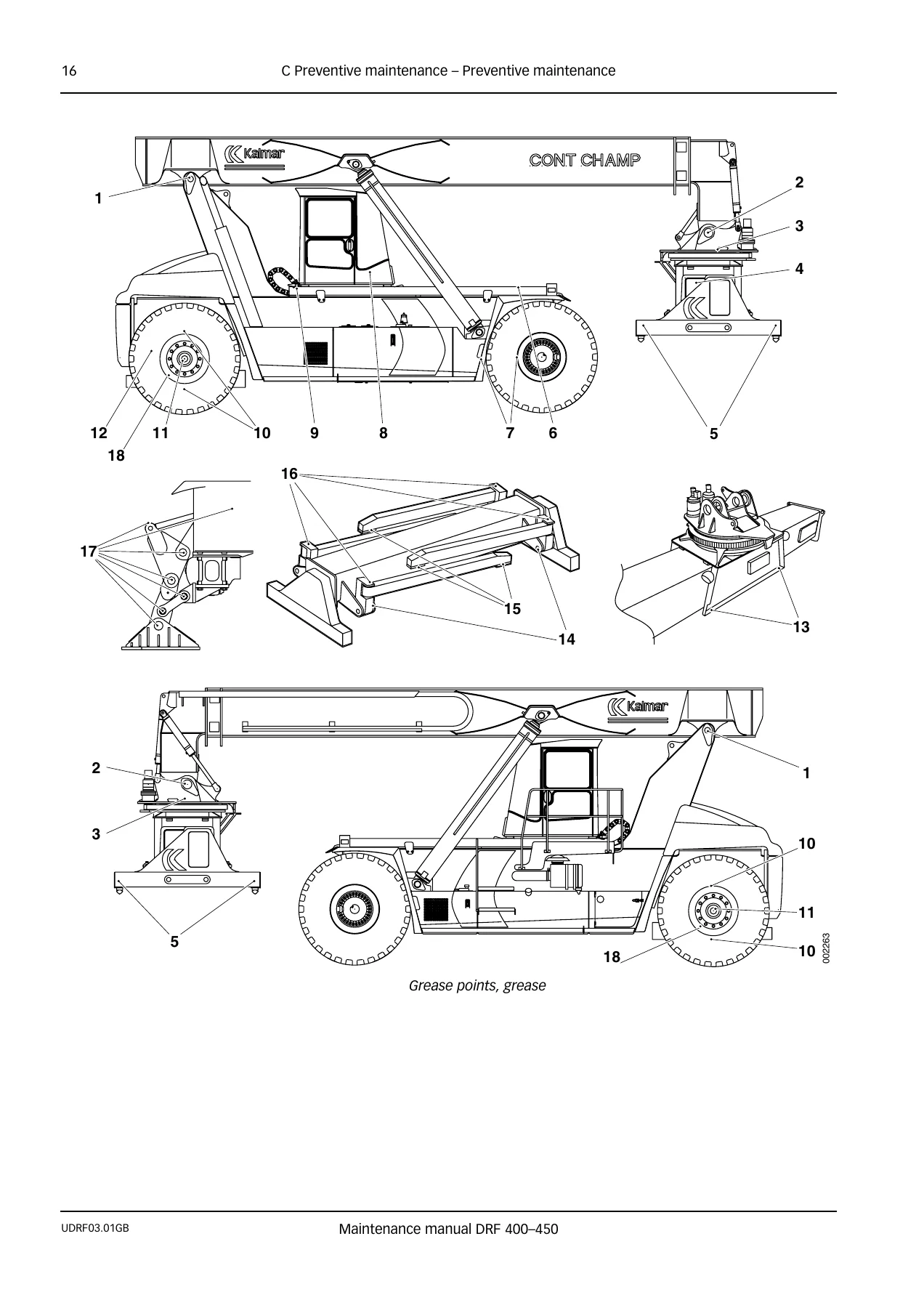
Preventive maintenance is treated in detail. The 50-hour check for a new machine lists every action to be carried out after the first week of operation, from leakage checks on oil, coolant and the exhaust system to fuel pre-filter draining, propeller shaft check-tightening, brake function checks, wheel nut check-tightening and hose connection checks. The service schedule then splits work into 500-hour, 1000-hour and 2000-hour services with a reference for every object and action, and the lubrication charts cover the 500-hour and 1000-hour points with the machine’s grease points illustrated. A check and service log table is included for recording completed work against operating hours.
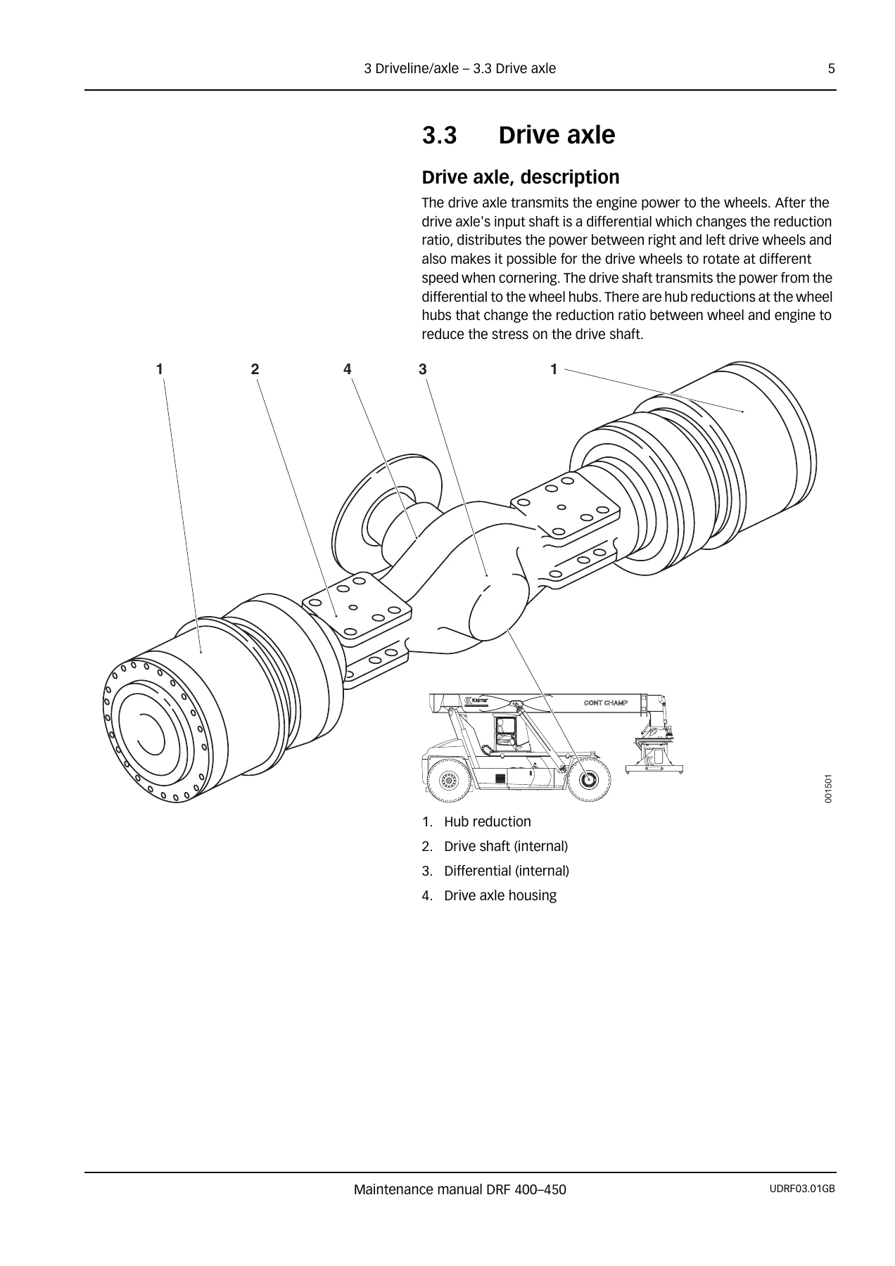
On the engine side, the Kalmar DRF 400-450 is covered for the Volvo TWD1240VE, Volvo TAD1250VE and Cummins QSM11 alternatives, with component positions drawn for each and separate bleeding, filter and oil-change procedures where the engines differ. Transmission servicing, drive axle and hub reduction oil changing, brake system pressure checks on the accumulator charging valve, parking brake adjustment, tyre and rim inspection, glide plate measurement on the boom and attachment, spreader chain adjustment, twistlock wear limits, support jack and weight indicator calibration all appear as step-by-step instructions with the relevant values.
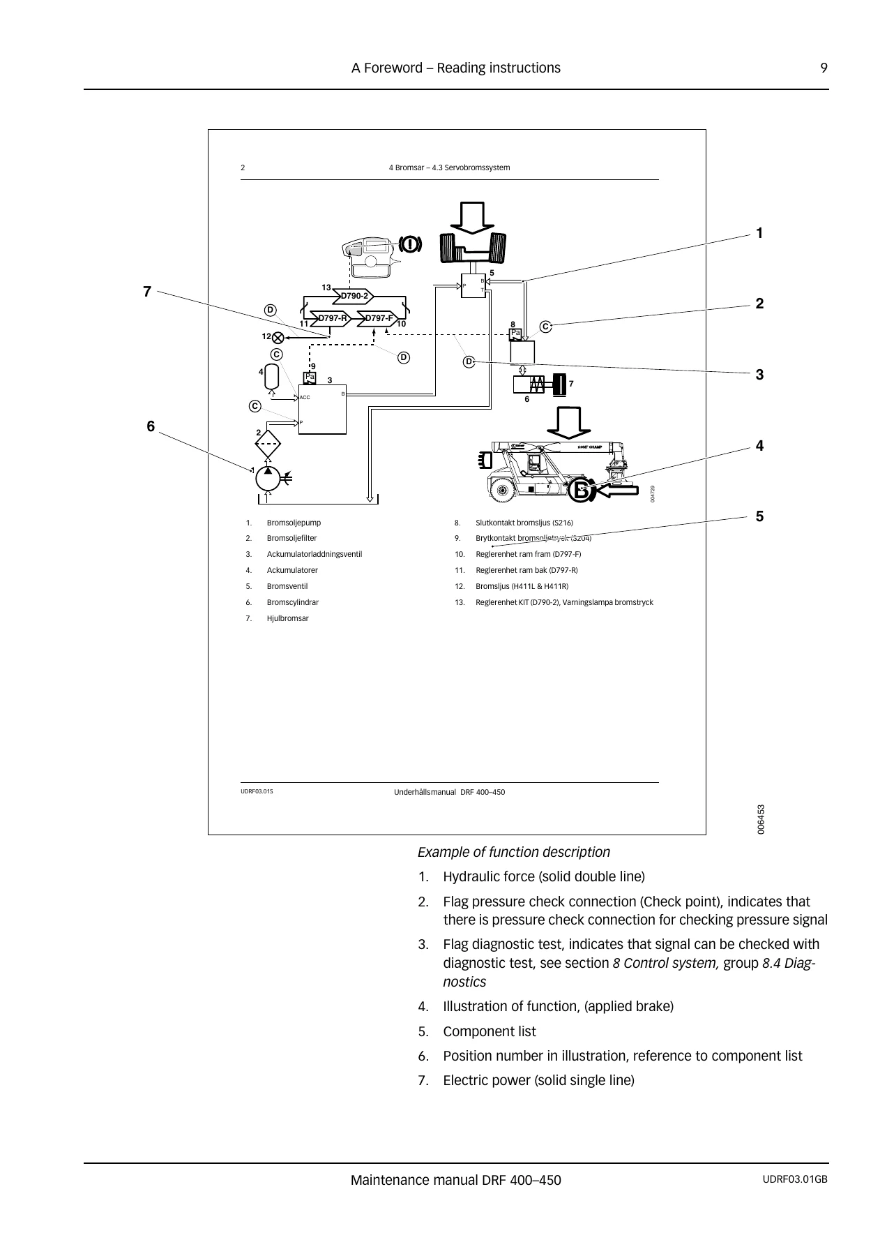
The control system chapter explains the monitoring functions that protect the machine, including the overloading system, by-passing, load centre limitation, height limitation and speed limitation, along with the error code levels and the diagnostic menu groups used to read input and output signals during troubleshooting.
Who This Manual Suits
This is the right document for a service organisation or owner-operator running Kalmar DRF 400-450 reachstackers who needs the scheduled maintenance programme, the checking and adjustment values, and the system descriptions that support fault-finding. It suits technicians performing 500-hour and 1000-hour services, fitters working on the boom, spreader, twistlocks and lift legs, and anyone setting up a maintenance plan against the Kalmar intervals. Because it is the maintenance manual rather than the workshop manual, it stops short of component overhaul and internal repair instructions.
Get the Kalmar DRF 400-450 Maintenance Manual
With this manual on hand you can run the full preventive maintenance programme on a DRF 400-450, work through the checking and adjustment procedures for the load handling attachment, brake system, drive axle and hydraulics, and read the machine’s monitoring and diagnostic functions instead of guessing at a fault. Following the stated intervals and the Kalmar-approved oils, greases and tightening torques is what keeps a container handler in service and protects the components that are expensive to replace.
IMAGES PREVIEW
The Kalmar DRF 400-450 Maintenance Manual is delivered as an instant PDF download after payment. There is no shipping and nothing to wait for. Open it on a laptop, tablet or phone in the workshop, print the pages you need for the job in front of you, and keep the rest of the manual to hand for the next service.
Reviews
There are no reviews yet.