
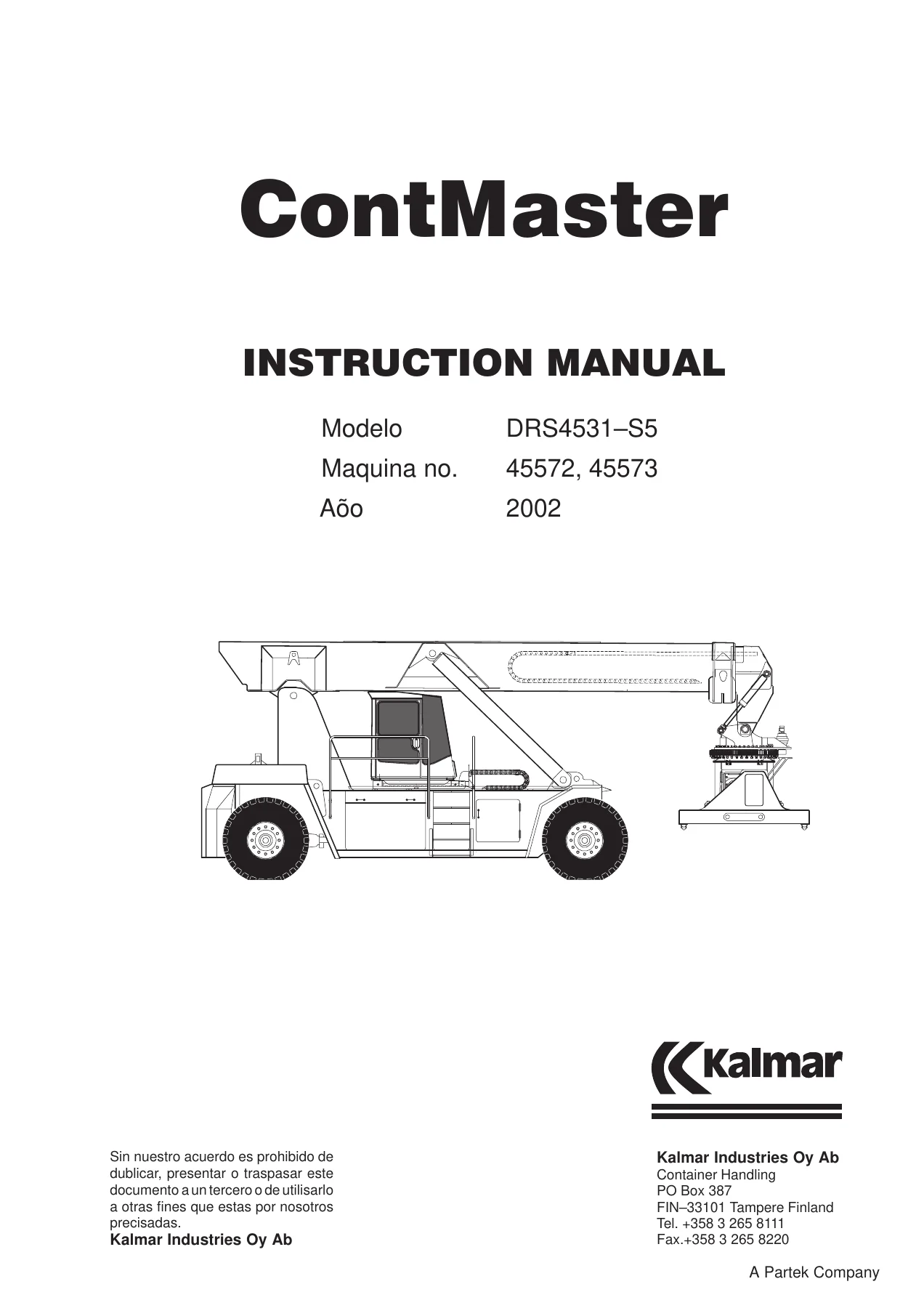
Kalmar DRS4531-S5 Reach Stacker Instruction & Service Manual 2002 – Machines 45572, 45573
Original price was: $44.95.$27.95Current price is: $27.95.
Complete 760-page Kalmar DRS4531-S5 Reach Stacker documentation set for machines 45572 and 45573 (2002): operator’s instruction manual, full workshop service manual and appendices in one PDF. Covers the Cummins MTA 11C engine, Clark 15.5 HR34431/36431 transmission, drive and steering axles, hydraulics, electrical system, cab, boom, Toplift spreader and twistlocks, plus hydraulic and electrical diagrams.
Description
The Kalmar DRS4531-S5 instruction manual is the documentation set issued for machines 45572 and 45573, built in 2002. Across 760 pages it gathers the operator’s manual, the complete workshop service manual and the appendices into a single file, giving owners, operators and maintenance technicians one reference that runs from daily checks and safe container handling through to transmission overhaul, hydraulic valve adjustment and electrical fault-finding.
File Details
- Manual type: Operator’s instruction manual combined with the workshop service/repair manual and appendices
- Brand: Kalmar Industries Oy Ab, Container Handling
- Model: DRS4531-S5 Reach Stacker
- Machine numbers covered: 45572, 45573
- Year: 2002
- Languages: Spanish for the main body; English for the Cummins M11 engine manual and the Clark transmission manual in the appendices
- Reference shown in the operator’s section: KH11-0115
- Page count: 760
- File format: PDF
Chapters Covered
- A – Manual del operador (Operator’s manual)
- 11.1 General information
- 11.2 Technical specification and handling of the equipment
- 11.3 Reach stacker identification plate
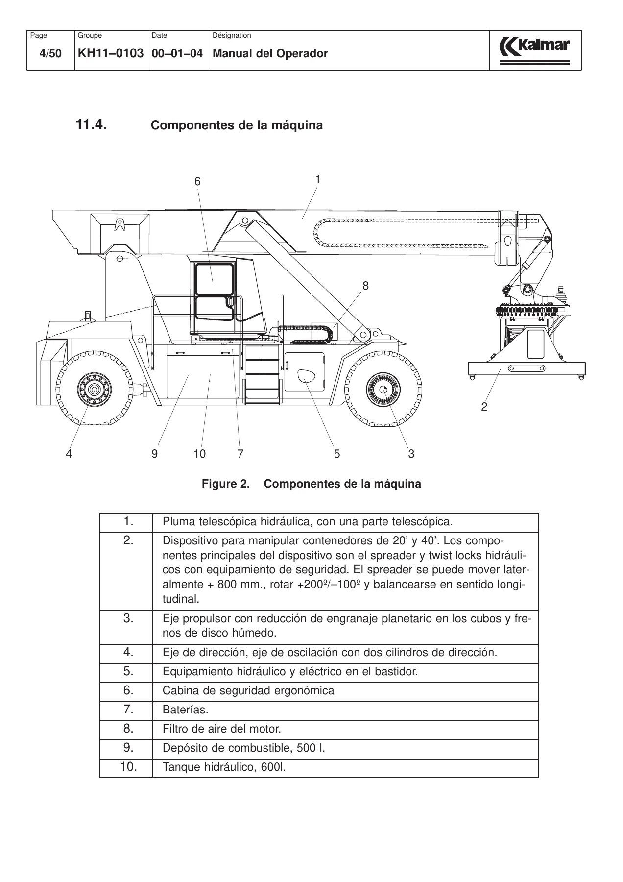
- 11.4 Machine components
- 11.5 Technical details and lifting capacity
- 11.6 Working environment – vibration and noise levels
- 11.7 Cab control devices – controls, left and right instrument panels, control lever panel, VK-3 overload control system, steering wheel adjustment, seat
- 11.8 Transferring the cab; KKRV 100-100 load scale
- 11.9 Instructions for safe use – general safety precautions, overturning, collisions, damaged transport, system alterations, wind influence, RSD safety instructions
- 11.10 Driving and operating instructions – engine start/stop, driving, machine function control system, Toplift container handling device, container handling, lowering onto a trailer, hook lifting, finishing a work shift, carrier safety monitoring
- 11.11 Temporary parking, returning the carrier to use, complete overhaul, taking out of service
- 11.12 Daily maintenance – engine oil, fan belt, transmission oil, coolant, screen wash, air filter, wheels, hydraulic oil, fuel, container contact sensor pins, central lubrication tank
- B – Servicio (Service manual)
- 00 General information / regular maintenance – safety rules for service work, conversion tables, screw torque values, lubricant recommendations, maintenance points and schedules, running-in and initial maintenance
- 01 Power unit – driveline, engine, Clark 15.5 HR34431/36431 transmission, inspection instructions, stall test
- 02 Power transmission – drive axle, differential and planetary gear oil changes, brake cover, friction discs, steering axle, wheel bearings, wheels and rims
- 03 Hydraulic system – operating principle, pumps, boom movement, hydraulic steering, attachment hydraulics, cleanliness of hydraulic systems, hydraulic brake system, diaphragm accumulators, Orbitrol steering, hydraulic components
- 04 Electrical system – general information, safety, battery maintenance, alternator, welding precautions, VK-3 overload control system, RSV-002 control unit, relay box and control module A81
- 05 Cab – cab electrical system, circuit board and tester, electric box, electro-hydraulic engine speed control and pedal calibration
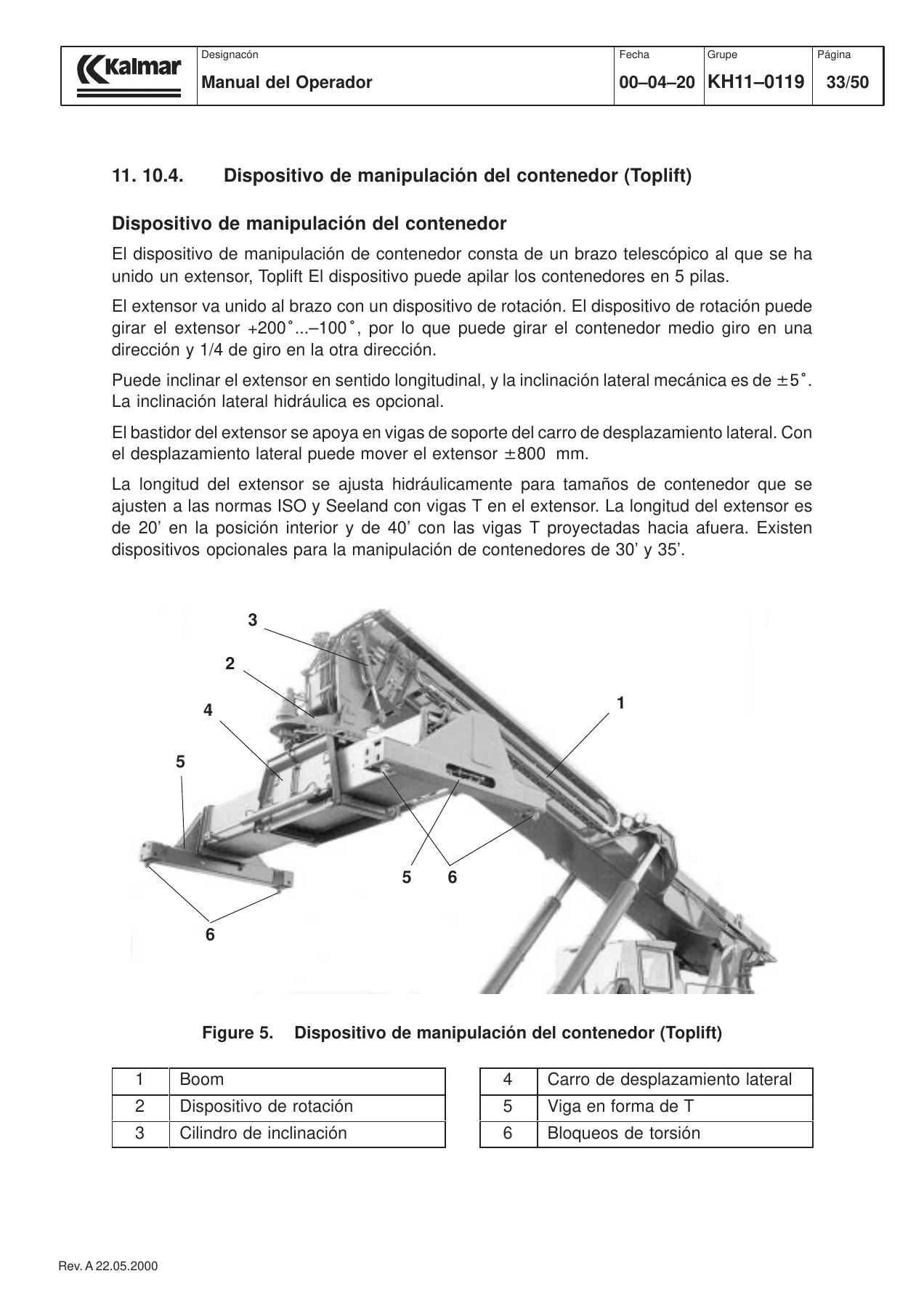
- 06 Working devices – boom maintenance and slide pads, lifting cylinder, slewing device and side-shift carriage, Toplift container handling device, spreader electrical equipment, twistlock inspection intervals and disassembly
- 07 Chassis and protections
- 08 Equipment – air conditioning
- C – Appendices
- Warranty information
- Environmental policy and product environmental issues
- Hydraulic diagrams – basic machine, main valve, spreader, cab transfer, brake, regulator control, twistlock, side-shift and longitudinal tilt instructions
- Electrical diagrams – RS2001/T5658730 series covering power supply, start/stop, alarms, gauges, lights, wipers, transmission control, air conditioning, cab transfer, hydraulic control, module A81 and fuse layouts
- Boom assembly drawings KG6027/1-5
- Balanza de carga KKRV 100-100 (load scale)
- Engine manual – Cummins M11 Series Engines operation and maintenance
- Transmission manual – Model 36000 Powershift Transmission, 3-4-6 speed short drop
Read as a whole, the Kalmar DRS4531-S5 instruction and service manual works on three levels. The operator’s section explains what the machine is, where its limits lie and how it must be driven, loaded and shut down. The service section then takes those same assemblies apart – the Cummins engine and Clark transmission, the drive axle with its planetary hubs and wet disc brakes, the oscillating steering axle, the load-sensing hydraulic system, the electrical and overload control circuits – and describes how each is inspected, measured, adjusted and rebuilt. The appendices close the loop with the supporting material a workshop actually needs at the bench: hydraulic and electrical schematics, boom assembly drawings, the Tamtron KKRV 100-100 load scale documentation and the manufacturer’s own engine and transmission manuals. Nothing in the chain is left as an assumption.
What the Operator’s Section Gives You
The operating half of the manual is built around the realities of container handling rather than generic machine descriptions. It documents the cab layout control by control, including the left and right instrument panels, the control lever panel, the handle functions and the seat and steering column adjustments. The VK-3 overload control system is explained with its green, yellow and red load ranges, the alarm that sounds between 90 and 100 percent of safe lifting capacity and the automatic restriction that leaves only boom retraction available above 100 percent – together with the limited circumstances in which the S85 bypass switch may be used at all.
Safety content is treated as a full chapter rather than a footnote. It covers overturning, collisions, damaged equipment, unauthorised system alterations, the influence of wind up to the permitted maximum, correct driving position with the container, correct and incorrect transfer positions without a load, speed limits when stacking or running with the telescope extended, and the behaviour expected when transferring the cab. Daily maintenance is then listed as a practical round of checks: engine oil, cooling fan belt, transmission oil, expansion chamber coolant level, screen wash, air filter indicator, wheel condition, hydraulic oil level, fuel, the four container contact sensor pins and the central lubrication reservoir.
What the Service Section Gives You
The workshop section is where the depth shows. Group 00 opens with service safety rules, conversion tables, general screw torque tables and a full lubricant and fluid recommendation chart covering engine oil, Clark transmission fluid, hydraulic oil, axle and planetary gear oil, slewing transmission oil and greases. Maintenance points are laid out with their operating-hour intervals – daily, 50, 250, 500, 1000 and 2000 hours – and separate scheduled maintenance tables are provided for the engine, the gearbox and power unit, the steering, the hydraulics, the boom, the spreader and the remaining systems.
From there the groups work through the machine system by system. Group 01 covers the power unit, including the transmission oil level check, oil change procedure, sectioned transmission views, the oil pump assembly, selector valve, pressure measurement points, clutch pressures, torque converter outlet pressures and a troubleshooting table for low clutch pressure, converter feed problems, overheating and noise. The stall test procedure for checking engine and transmission condition is included with its safe operating limits.
Group 02 deals with the drive axle and steering axle: differential and planetary oil change intervals, the torque table for the axle assemblies, brake cover plugs and torque values, friction disc thickness limits for 13, 17 and 22 inch brakes, coolant cover pressure measurement, wheel hub bearing adjustment with its pre-torque and final torque figures, pinion shaft bearing shim calculations with worked examples, pinion nut torque values, differential bearing rolling resistance and backlash settings. The steering axle section covers pivot pin installation and tightening, wheel bearing adjustment and lubrication points, and the turning resistance check for the steering knuckle bearings with the specified torque range and adjustment procedure.
Group 03 covers the hydraulic system in detail, including the function of each pump circuit, boom lift and telescope control, accelerated lifting, hydraulic steering through the Orbitrol unit, attachment functions, longitudinal sway, rotation, twistlock operation, cab transfer and spreader length adjustment. It also contains extended guidance on hydraulic cleanliness – sources of contamination, solid particles, gases and liquids, preventive measures during component changes and repairs, leak detection and hydraulic cylinder disassembly with surface inspection requirements. The hydraulic brake system is documented with its adjustment and measurement points, brake pressure setting procedure, brake pedal adjustment and parking brake adjustment.
Group 04 handles the electrical system: nominal 24 VDC, battery maintenance and electrolyte checks, alternator precautions, welding precautions, and fault location through the fuse and wiring diagrams. It also documents the VK-3 overload control system in full, including calibration of the amplifier, limit 1 at 90 percent load, limit 2 at 100 percent load, display setting and the resistance and voltage measurements used when troubleshooting the sensor circuit, plus the RSV-002 control unit for travel speed and engine speed during direction changes.
Group 06 is dedicated to the working devices. It explains boom maintenance, slide pad inspection and renewal at the front and rear of the boom, boom clearance adjustment, telescope cylinder assembly, the boom electrical equipment with its red, yellow and green indicator lamps, and the lifting cylinder with its lock valve. The Toplift spreader section describes slide pad checks, lubrication of the length cylinders, slewing device and twistlock cylinders, and gives the twistlock inspection interval, disassembly and assembly sequence, tightening torque and the non-destructive testing guidance for crack detection.
Hydraulic and Electrical Diagrams, Boom Drawings and Load Scale
The appendices reproduce the schematics as separate drawings rather than reduced thumbnails. The hydraulic set covers the basic machine, the main valve, the spreader, cab transfer, the brake circuit, the regulator control and the twistlock, side-shift and longitudinal tilt adjustment instructions. The electrical set runs through the RS2001/T5658730 diagram family: main supply, start and stop, alarms, gauges, road and work lights, wipers and washers, transmission control, air conditioning, cab transfer and oil cooler, hydraulic on/off, stability control, spreader retraction and extension, the A81 control module and the fuse layout diagrams. Boom assembly drawings KG6027/1-5 are included with the fitting notes for the cylinder centring and shim arrangement. The Tamtron KKRV 100-100 load scale is documented with its weighing principle, static weighing method and the caution about replacing the backup battery with the scale powered. The Cummins M11 engine manual and the Clark Model 36000 Powershift transmission manual complete the set.
Put the Kalmar DRS4531-S5 Documentation to Work
With this manual on hand you can carry out the full daily and scheduled maintenance round on the DRS4531-S5, set the VK-3 overload control correctly, diagnose transmission clutch pressure and converter faults, adjust the parking brake and brake pedal, set hydraulic relief and control valves to their specified pressures, renew boom slide pads and twistlocks, and trace an electrical fault from the fuse layout through to the correct terminal on module A81. Every value you need – torque figures, pressure settings, clearances, thickness limits, oil capacities, adjustment turns – is printed alongside the procedure that uses it, so the work is done to the manufacturer’s numbers instead of by feel.
That matters on a machine of this class. An overload system set even slightly wrong, a brake adjusted without its pressure check, a twistlock put back into service without inspection or a hydraulic system opened without contamination control all carry consequences far beyond the cost of the manual. Having the correct sequence, the correct setting and the correct limit in front of you is what keeps the reach stacker, the container and the people around it safe.
IMAGES PREVIEW
Delivery is instant. The file is a downloadable PDF – no shipping, no waiting, no physical book to lose in the workshop. Open it on a laptop, tablet or phone at the machine, print the pages you need for the job, and keep the complete Kalmar DRS4531-S5 Reach Stacker instruction and service manual for machines 45572 and 45573 available for every service interval that follows.


Reviews
There are no reviews yet.