
Kawasaki 65ZV-2 Wheel Loader Shop Manual – Isuzu 4HK1X Service & Repair PDF (93207-00771)
Original price was: $71.95.$47.95Current price is: $47.95.
Complete Kawasaki 65ZV-2 wheel loader shop manual, document 93207-00771, August 2011. Covers the Isuzu 4HK1X engine and every major machine system with function, structure, check and adjustment procedures. Instant PDF download.
Description
Kawasaki 65ZV-2 Wheel Loader Shop Manual – Document 93207-00771
This is the complete Kawasaki 65ZV-2 wheel loader shop manual, published under document number 93207-00771 and dated August 2011. It is the service documentation for the 65ZV-2 wheel loader powered by the Isuzu 4HK1X engine, and it covers the machine from general information and performance measurement all the way through chassis, power train, torque converter and transmission, hydraulics, brakes, electrical systems and the operator station, closing with a full drawings and diagrams section. The manual follows Kawasaki’s own section numbering — 00 General Information, 03 Measurement for Performance Check, 12/13 Chassis Group, 22/23 Power Group, 32/33 Torque Converter and Transmission Group, 42/43 Hydraulic Group, 52/53 Brake Group, 62 Electrical Group, 72/73 Operator Station Group and 92 Drawing & Diagrams — so that every Function & Structure section that explains how a system works is paired with a Check & Adjustment section that tells you how to measure it, set it and diagnose it. That pairing is what makes this manual useful both for understanding a fault and for putting the machine back into specification.
File Details
- Manual type: Shop Manual
- Brand: Kawasaki
- Model: 65ZV-2 Wheel Loader
- Engine: Isuzu 4HK1X
- Language: English
- Page count: 503 pages
- File format: PDF
- Document number: 93207-00771
- Publication date: August 2011
Chapters Covered
- 00 General Information
- 03 Measurement for Performance Check
- 12 Function & Structure – Chassis Group
- 13 Check & Adjustment – Chassis Group
- 22 Function & Structure – Power Group
- 23 Check & Adjustment – Power Group
- 32 Function & Structure – Torque Converter and Transmission Group
- 33 Check & Adjustment – Torque Converter and Transmission Group
- 42 Function & Structure – Hydraulic Group
- 43 Check & Adjustment – Hydraulic Group
- 52 Function & Structure – Brake Group
- 53 Check & Adjustment – Brake Group
- 62 Function & Structure – Electrical Group
- 72 Function & Structure – Operator Station Group
- 73 Check & Adjustment – Operator Station Group
- 92 Drawing & Diagrams
General Information (Section 00)
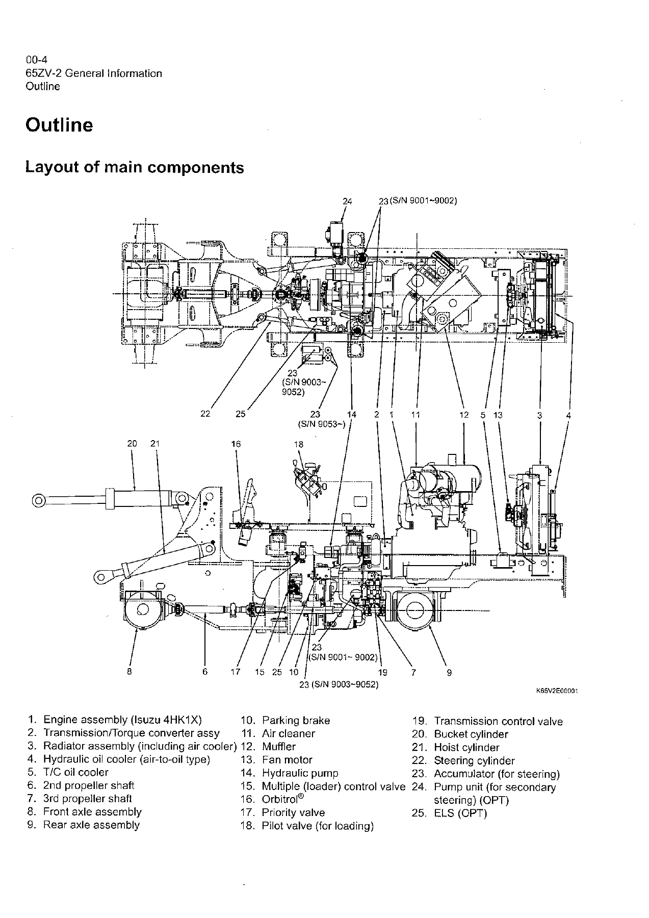
Section 00 sets up the rest of the manual. It explains how the manual is organized, lists the safety precautions that apply to service work, and gives the layout of the main components on the machine. From there it provides the inspection and maintenance table with service intervals, recommended lubricants and coolant specifications, the lubrication chart, the weight of main components, bolt tightening torques for metric and unified thread in 8.8 and 10.9 strength, hose band tightening torques, and the liquid gasket and screw lock agents Kawasaki specifies. It closes with cautions on welding repair service — where to ground the welder, how to protect cylinders and plated sections, and what to disconnect before welding.
Measurement for Performance Check (Section 03)
Section 03 is the baseline for evaluating a 65ZV-2 that is already in service. It lists the safety cautions for running the machine during measurement, then gives the standard measurement values for performance check: engine speeds at low idle and high idle, torque converter stall speed, multiple control valve relief speed, transmission clutch pressures, cylinder drift limits, boom rising time, full steering time, relief valve setting pressures, fan maximum and minimum revolutions, brake performance values, accumulator charge time, and declutch engagement. These are the numbers you compare against when a machine feels down on power, slow on the boom, or weak on the brakes.
Chassis Group (Sections 12 and 13)
The chassis group covers the front chassis and loading linkage, including the loading linkage pins, the rear chassis, the fuel tank, the floor board mount and viscous mount, the center pin assemblies, and the dust seals. Section 13 gives the check and adjustment procedures for the linkage pins, liners, center pin and adjusting shims, with clearances and shim thicknesses so the articulation and linkage can be brought back to specification.
Power Group (Sections 22 and 23)
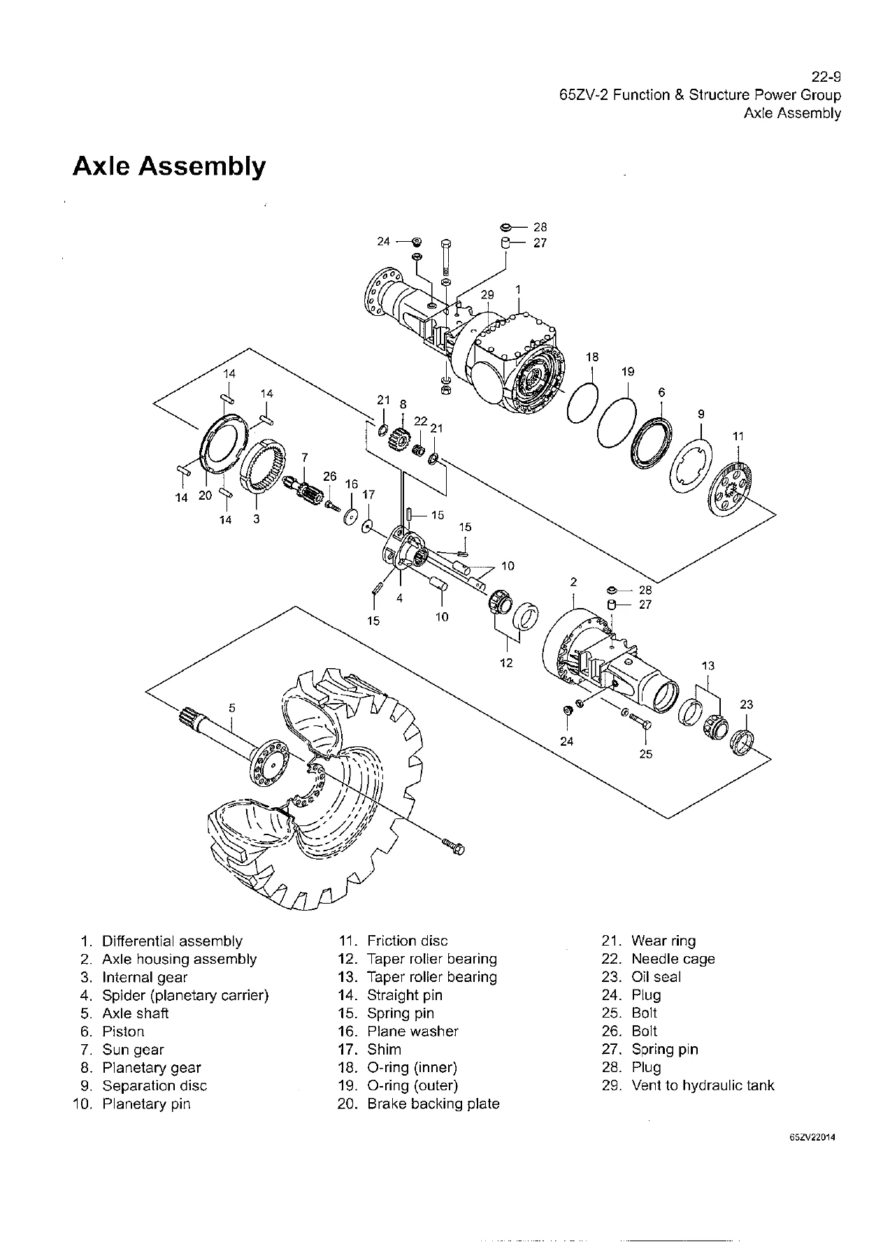
The power group documents the power line from the engine through the transmission and propeller shafts to the axles. It covers the engine and transmission mounts, the radiator and its mount, the second and third propeller shafts, the axle assembly, axle support, and the differential gear — including the torque proportioning differential (T.P.D.), its function and how it operates compared with a conventional differential. Section 23 covers measuring engine speed and engine oil pressure, propeller shaft phase and second propeller shaft alignment, and the tightening torques for the driveline.
Torque Converter and Transmission Group (Sections 32 and 33)
This is the deepest part of the drive train documentation. It explains the torque converter structure, power flow path and torque multiplication, the torque converter gear pump, the clutch combination and shift lever positions, the gear train and number of teeth, the hydraulic system and circuit diagrams, oil flow through the torque converter and clutches, the control valve, the modulation mechanism and its clutch control oil pressure curve, the accumulators, and the clutch solenoid valves. Section 33 gives the clutch oil pressure measurement procedure and values.
Hydraulic Group (Sections 42 and 43)
The hydraulic group is the largest section. It begins with flushing the hydraulic circuit, cautions on hydraulic parts replacement, and the hydraulic circuit symbols, then moves through hydraulic system operation, layout of hydraulic units and the hydraulic tank. It covers the hydraulic pump, hydraulic cylinders for boom, steering and bucket, the loading system, the reducing valve for pilot pressure, the pilot valve, the multiple control valve KML22/2T including its main relief, overload relief and make-up valves, the ride control option, the steering system, the priority valve, the Orbitrol unit, the accumulators, the efficient loading system (ELS), the fan motor system and the secondary steering option. Section 43 gives the relief valve and reducing valve setting pressures and the hydraulic cylinder natural drift values.
Brake Group (Sections 52 and 53)
The brake group covers the service brake and parking brake, the unloader valve, valve unit, accumulators, in-line filter, brake valve, service brake friction and steel plates, the brake circuit air bleeding procedure, the parking brake solenoid valve and manual release, and the pressure sensors for the stop lamp and declutch. Section 53 gives the brake circuit oil pressure checks, service brake performance and friction plate wear measurement, and parking brake performance and clearance adjustment.
Electrical Group (Section 62)
The electrical group explains how to use the wiring diagrams, with translated usage pages for French, German, Italian, Spanish and Portuguese, the cable colour codes, sensor mounts, fuses and fusible links, the engine start circuit, the charging circuit and ECM information, the transmission control and monitor circuits, the machine control unit (MCU), the monitoring system, the instrument panel and gauges, the MODM function and monitors, the electrical detent circuit, bucket leveler, lift and lower kickout, sensors and diodes. It includes diagnostic trouble code (DTC) information and diode check methods.
Operator Station Group (Sections 72 and 73)
The operator station group covers the cabin, glass, wiper mount and motor, operator seat, steering and transmission shift lever, tilt case, column shaft and shift lever, plus the Denso air conditioner components, structure, cooling mechanism, cooling circuit, electrical circuit, component functions, refrigerant charge and troubleshooting. Section 73 gives the air conditioner check and adjustment procedures, including lubricating oil quantity, compressor magnetic clutch air gap, V-belt adjustment and parts to be replaced periodically.
Drawing & Diagrams (Section 92)
The drawings and diagrams section collects the large-format references in one place: the axle assembly, torque converter and transmission, hydraulic and brake circuits, the brake circuit, the electrical wiring diagrams and connection diagrams for both early and later serial number ranges, the cabin air conditioner electrical diagrams, the equipment operation table, the electrical equipment layout, the MODM operation outline, and the MODM input/output signal correspondence table.
What This Kawasaki 65ZV-2 Shop Manual Lets You Do
With the Kawasaki 65ZV-2 shop manual in hand you can carry out the full range of service work the machine needs: measure engine speed and oil pressure against the standard values, check and adjust the clutch oil pressure, set the loading and steering relief pressures, diagnose the torque proportioning differential, service the brake accumulators and service brakes, bleed the brake circuit, trace an electrical fault through the wiring diagrams, read and clear diagnostic trouble codes, service the air conditioner, and set up the boom and bucket linkage. The check and adjustment sections give the actual values — for example low idle at 800 ± 50 min-1, high idle at 2,450 ± 50 min-1 on early serial numbers and 2,410 ± 50 min-1 on later ones, main relief pressure at 20.6 ± 0.5 MPa (210 ± 5 kgf/cm2), overload relief at 23.5 ± 0.5 MPa (240 ± 5 kgf/cm2), and pilot reducing pressure at 3.5 MPa (36 kgf/cm2) — so you are working from the same numbers the machine was built to, not from guesswork.
Having the right procedures and specifications matters on a wheel loader because so much of the machine is interconnected. A transmission clutch that is set up wrong will not just shift badly; it will load the torque converter and the engine differently, and it will show up as a performance complaint somewhere else. A relief valve set too high will not just run hot; it will shorten pump and hose life. The 65ZV-2 shop manual is organized so that the function of each system and the adjustment of that system sit side by side, which is exactly what you need when a fault could be hydraulic, electrical or mechanical.
IMAGES PREVIEW
Instant PDF Download of the 65ZV-2 Shop Manual
This Kawasaki 65ZV-2 wheel loader shop manual is delivered as an instant PDF download. There is no shipping, no waiting for a disc, and no region restrictions. Open it on a laptop, tablet or phone in the workshop, print the pages you need for the job, and keep the full document on hand for the next repair. Whether you are servicing the Isuzu 4HK1X engine, rebuilding a transmission clutch pack, setting relief pressures, or tracing a wiring fault, the complete 65ZV-2 shop manual is one download away.
Reviews
There are no reviews yet.