
Kawasaki 90ZV-2 Wheel Loader Shop Manual – Troubleshooting & Performance Checks PDF Download
Original price was: $49.95.$32.95Current price is: $32.95.
Kawasaki 90ZV-2 Wheel Loader Shop Manual covering complete troubleshooting tables and performance check procedures. 117-page PDF, doc 93213-00450.
Description
Kawasaki 90ZV-2 Wheel Loader Shop Manual — Troubleshooting & Performance Checks
This Kawasaki 90ZV-2 Shop Manual is the technician’s reference for diagnosing faults and verifying machine performance against factory specifications. Published under document number 93213-00450 on May 25, 2009, this 117-page PDF covers the full troubleshooting matrix and performance check procedures for the 90ZV-2 wheel loader. Every symptom, possible cause, and solution is laid out in the quick-reference tables that make this manual the go-to resource for field diagnosis and systematic fault-finding.
File Details
- Manual type: Shop Manual — Troubleshooting & Performance Checks
- Brand: Kawasaki
- Model: 90ZV-2 Wheel Loader
- Document number: 93213-00450
- Date: May 25, 2009
- Language: English
- Page count: 117
- File format: PDF
Chapters Covered
- 01 Troubleshooting
- 03 Measurement for Performance Check
01 — Troubleshooting
The troubleshooting chapter opens with cautions regarding troubleshooting, guidance on how to use the quick troubleshooting table, and detailed safety precautions. The quick troubleshooting tables are divided into four major groups: Torque Converter and Transmission Group (10 symptom categories covering machine movement failures, shock on starting, time lag, low power, overheating, reverse rollback, automatic speed change, and downshift button issues), Hydraulic Group (12 categories including boom/bucket non-operation, low power, cylinder drift, spongy hydraulics, bucket leveler, steering problems, ELS function, ride control, fan motor, and abnormal noise), Brake Group (5 categories: brake performance, dragging, buzzer activation, accumulator pressure rise, and parking brake), and Electrical Group (instrument panel indication, controller fuse failure, chassis error codes CN121–CN913, and engine error codes EG155–EG2964). The operator station group covers air conditioner fault diagnosis with error codes E11–E51, a fault diagnosis flowchart, and basic checks for control mechanism, V-belt, refrigerant level through sight glass, and piping connections.
03 — Measurement for Performance Check
This chapter delivers the standard measurement values for performance checks, split into two serial number ranges (S/N 9001~9350 and S/N 9351~). Coverage includes engine speed measurement (low idle 800±50 rpm, high idle 2,250±50 rpm), torque converter stall speed, multiple control valve relief mode, clutch oil pressure (1.3±0.2 MPa at idle; 1.5±0.2 MPa at max), cylinder natural drift, boom rising time, full steering time, loading and steering circuit relief valve pressures (main relief 20.6±0.5 MPa; overload relief 23.5±0.5 MPa; steering overload 24.5 MPa), stop valve adjustment with reference dimensions, fan revolution measurement (maximum 1,155–1,650 rpm depending on temperature), service brake performance, parking brake performance, brake circuit oil pressure (cut-out 11.8±0.5 MPa; cut-in 6.9±1.0 MPa), accumulator charging time, number of brake pedal applications (at least 13 times), and declutch engagement (15 cm or less on 1/5 slope). Each procedure includes measurement instruments, warm-up requirements, step-by-step instructions, standard values, and possible causes of abnormal readings with solutions.
Quick Troubleshooting Tables — How They Work
The troubleshooting tables are structured by symptom: you find the complaint, then check the machine against the listed check points. Each possible cause is marked with a circle when it matches the condition, and the cause with the most check marks is generally the actual cause. If multiple causes have marks, you check each one starting from the easiest. This system lets you diagnose without disassembling parts. The tables cover every major system group on the 90ZV-2 wheel loader, from the torque converter and transmission through hydraulics, brakes, electrical, and operator station.
Error Codes and Diagnostics
The electrical group chapter includes comprehensive error code tables for both chassis and engine. Chassis input-side codes cover shift lever switch malfunctions (CN121, CN122, CN123), shift-up/down switch issues (CN141–CN146), T/M oil pressure sensor (CN151, CN152), machine speed sensor (CN161, CN162), E/G speed sensor (CN163–CN167), inching sensor (CN213, CN214), S/S potentiometer (CN232, CN234), and many more through CN913 for MCU voltage. Output-side failure codes cover solenoid valves for F, R, 1st–4th, D, H, LU, auto brake, speed change control, S/S, pressure increase, ride control, ELS, lower kickout relay, cooling fan, and hour meter. Engine fault codes reference the Cummins Engine troubleshooting fault codes list, with a table mapping codes such as EG155, EG166, EG172, EG184, EG212, EG234, EG415, EG418, EG428, EG441, EG442, EG449, EG451, EG452, EG465, EG482, EG485, EG488, EG524, EG546, EG551, EG553, EG554, EG559, EG598, EG689, EG731, EG753, EG757, EG758, EG778, EG951, EG1117, EG1358, EG1359, EG1361, EG1376, EG1595, EG1597, EG1845, EG1846, EG1852, EG1911, EG2185, EG2186, EG2215, EG2249, EG2261, EG2262, EG2265, EG2266, EG2311, EG2321, EG2322, EG2697, EG2964, and EG2973 to the appropriate machine models.
Performance Check Procedures — What You Can Measure
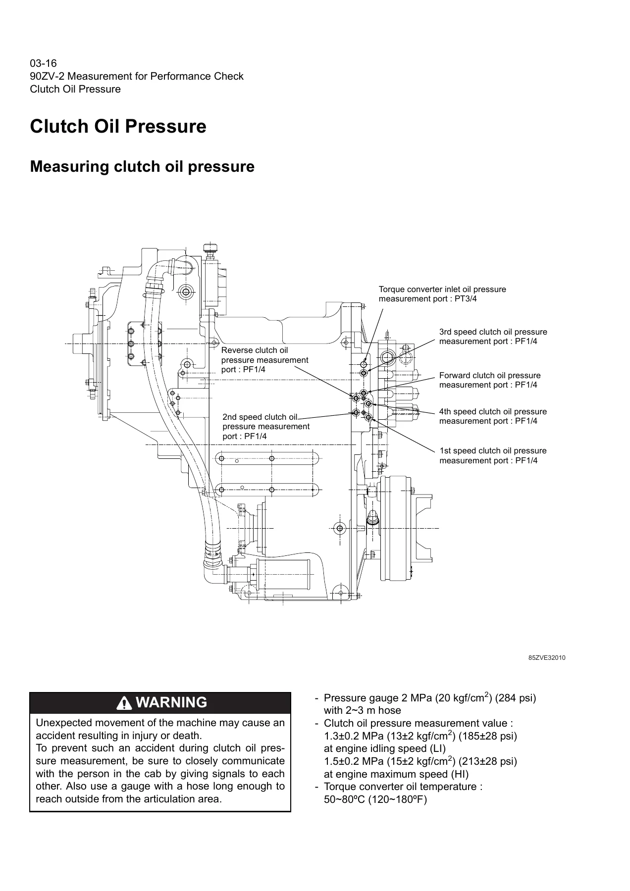
The measurement section isn’t just a list of specs; it’s a full procedure guide. You get detailed instructions for measuring engine speed using the MODM tachometer, including how to avoid “Hibernate mode” conditions. Stall speed measurement walks through the exact sequence: pressing the brake pedal, setting the parking brake, lowering the boom, rolling back the bucket, setting the declutch switch, and measuring at forward 3rd speed. The manual emphasizes that stall operation is limited to 20 seconds and torque converter oil temperature must not exceed 120°C (250°F), with a 10-second cooling interval required between repeats. Multiple control valve relief mode measurement is similarly detailed, with a 10-second limit and cooling cycle. Clutch oil pressure measurement includes a full diagram of the transmission with port locations for forward, reverse, 1st, 2nd, 3rd, 4th, and torque converter inlet ports (PF 1/4 and PT3/4 sizes). Hydraulic cylinder drift measurement covers both boom and bucket cylinders with a procedure using vinyl tape, scale, and stop watch, plus identification of defective parts by loosening the split flange and checking for compressed oil spouts. Boom rising time measurement is specified at idle (19±3.0 sec), 1,500 rpm (9.1±1.0 sec), and maximum speed (5.6±0.5 sec), with possible causes of slow boom rising including damaged main pump, steering pump, sticking multiple control valve spool, malfunctioning ELS valve, and internal oil leakage. Full steering time is measured at idle (4.4±0.5 sec), 1,500 rpm (2.5±0.3 sec), and maximum speed (2.5±0.5 sec), with a note about adjusting the stop valve stopper bolts and reference dimensions for articulation angle.
Relief Valve and Brake System Checks
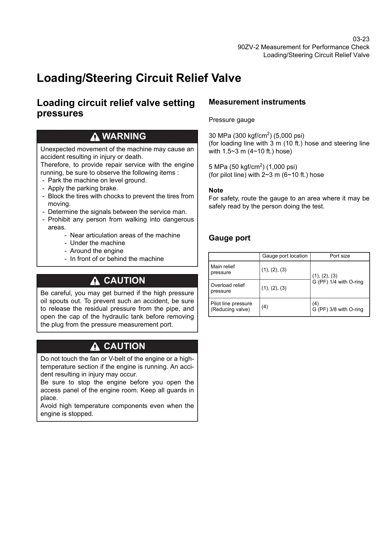
The loading/steering circuit relief valve chapter gives you the gauge port locations, port sizes (G (PF) 1/4 with O-ring for main and overload relief; G (PF) 3/8 with O-ring for pilot line), and the exact standard measurement values with hydraulic oil temperature at 50±5°C. You get procedures for measuring loading circuit main relief pressure, overload relief pressure, and pilot circuit relief pressure, plus adjustment instructions using the lock nut and adjusting screw. The steering circuit relief valve section follows the same pattern, with the added caution that the stop valve prevents oil pressure from reaching the set point when steering is fully turned, so you must apply the articulation stopper or screw the stopper bolt in until the front and rear chassis contact each other. The stop valve adjustment procedure includes a table matching articulation angle to clearance between machine body and stopper (11.8 mm at 38°, 17.6 mm at 37°, 23.6 mm at 36°) and stopper bolt length (31.7 mm, 34.0 mm, 36.3 mm), with a target articulation angle of 37°. Fan revolution measurement includes a circuit diagram of the fan motor assembly, flow control valve, and proportional solenoid valve, with a procedure to measure fan speed while the engine is at high idle, plus adjustment via the adjusting screw.
Service Brake and Parking Brake Testing
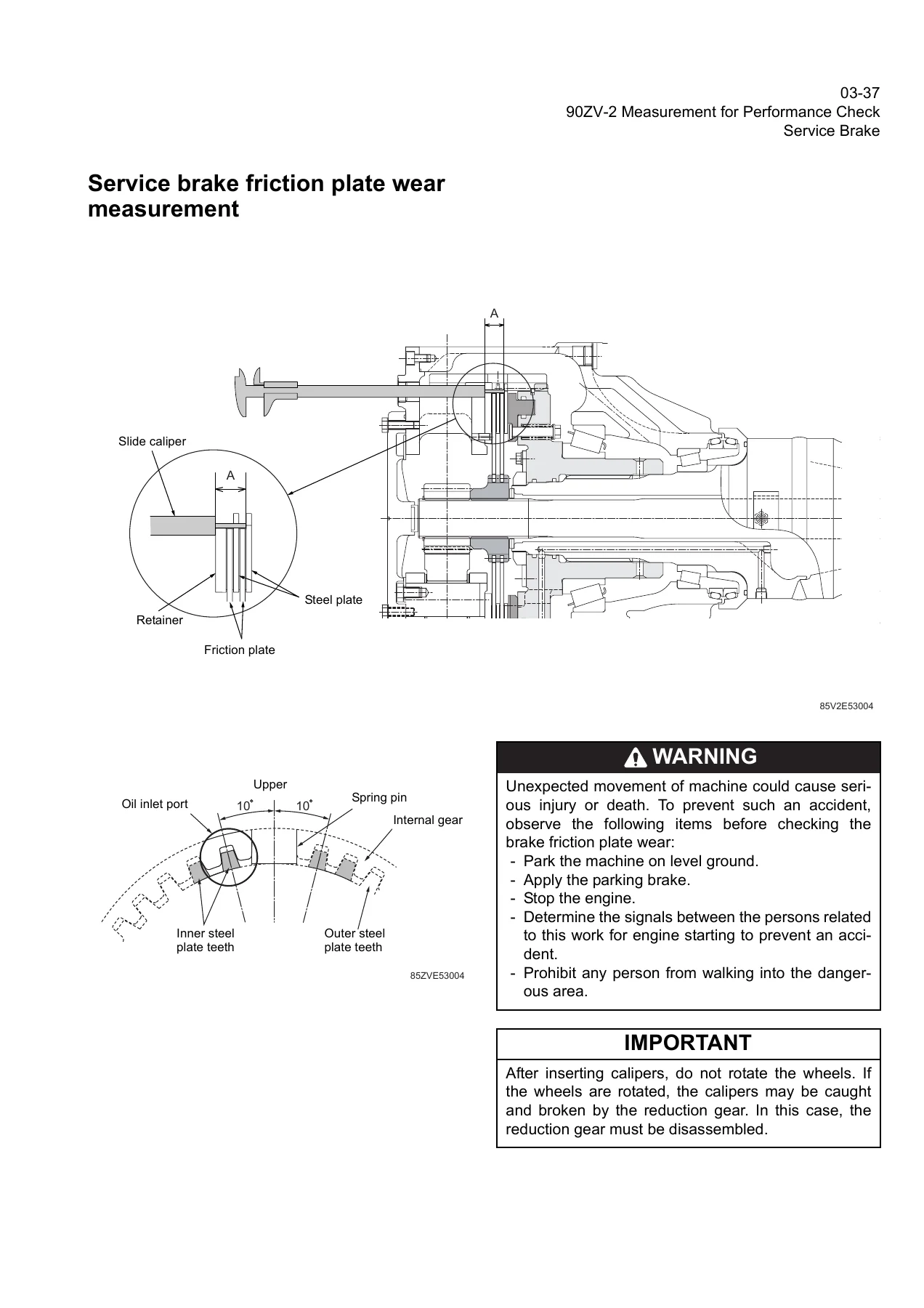
The service brake performance check offers two methods: Method 1 is a braking distance test on a level, straight, dry paved course at 20 km/h with a standard value of 8 m or shorter; Method 2 is a simpler stall test with the machine in 2nd reverse and brake pedal fully depressed, where the machine should not move at maximum engine speed. The manual notes that Method 2 is not accurate and should be reconfirmed with Method 1. Brake disc measurement uses calipers inserted through the inspection hole to check dimension A, with a wear limit of 25.1 mm (new: 29.0 mm). Parking brake performance check also offers two methods, with the slope method using a 1/5 slope (approx. 11°) and the stall method using 3rd reverse. Parking brake clearance adjustment is detailed with a diagram of the brake drum, adjusting screw, and brake shoe assembly, specifying a clearance of 0.23 mm after adjustment (range 0.1–0.25 mm). Brake lining abrasion check uses a wear limit of 0.8 mm from the lining to the rivet head. Brake circuit oil pressure measurement uses the ACF port on the valve assembly with cut-out pressure at 11.8±0.5 MPa and cut-in at 6.9±1.0 MPa. Accumulator circuit charging time is measured from low pressure alarm turn-off (3.9±0.5 MPa) to pointer stop (11.8±0.5 MPa). Number of brake pedal applications should be at least 13 times. Declutch engagement measurement uses a measurement rod attached to the step and a 1/5 slope, with a standard value of 15 cm or less.
Why This Kawasaki 90ZV-2 Shop Manual Matters
When a 90ZV-2 wheel loader goes down, you need answers fast. This manual gives you the diagnostic tables and performance check procedures to identify the problem, verify it against factory specifications, and make the repair correctly the first time. Instead of guessing at clutch pressures, relief valve settings, or brake performance thresholds, you get the exact values Kawasaki published for the 90ZV-2. The troubleshooting tables alone are worth the price — they cover every major system on the machine, from torque converter and transmission through hydraulics, brakes, electrical, and operator station. The performance check procedures give you a complete methodology for verifying that the machine is operating within specification after repairs, or for diagnosing gradual performance degradation. Whether you’re a professional heavy equipment mechanic, a fleet maintenance manager, or an owner-operator who does their own repair work, this manual is the reference you’ll reach for every time a 90ZV-2 comes into the shop.
IMAGES PREVIEW
This Kawasaki 90ZV-2 shop manual is delivered as an instant PDF download. There’s no shipping, no waiting for a physical book, and no risk of a damaged or lost package. The file works on any device — laptop, tablet, or smartphone — and every page is printable so you can take the relevant sections out to the machine. The quick troubleshooting tables are designed for field use, and the measurement procedures include the exact port locations, gauge types, and step-by-step instructions you need to get accurate readings. The document number 93213-00450 and May 25, 2009 date make it easy to verify you’re working from the correct reference. If you maintain or repair a Kawasaki 90ZV-2 wheel loader, this manual belongs in your library. Download it now and have the full troubleshooting and performance check reference available in minutes.
Reviews
There are no reviews yet.