
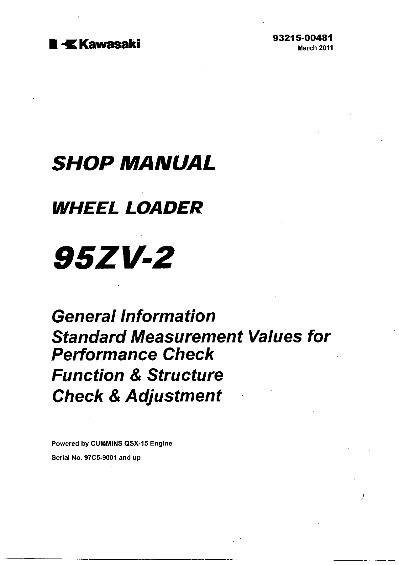
Kawasaki 95ZV-2 Wheel Loader Shop Manual – Cummins QSX-15 Engine Repair & Service PDF
Original price was: $52.95.$34.95Current price is: $34.95.
Complete Kawasaki 95ZV-2 Wheel Loader Shop Manual (Doc 93215-00481, March 2011). Covers Cummins QSX-15 engine, transmission, torque converter, hydraulics, brakes, electrical and operator station. Instant PDF download.
Description
Kawasaki 95ZV-2 Wheel Loader Shop Manual — Complete Service & Repair Documentation
This is the complete Kawasaki 95ZV-2 wheel loader Shop Manual, document number 93215-00481, published in March 2011. It covers machines powered by the Cummins QSX-15 engine from serial number 97C5-9001 and up. Whether you are servicing the drivetrain, diagnosing a hydraulic fault, rebuilding a brake circuit, or tracing an electrical problem, this manual provides the procedures, specifications, and diagrams needed to do the job correctly.
File Details
- Manual Type: Shop Manual
- Brand: Kawasaki
- Model: 95ZV-2 Wheel Loader
- Engine: Cummins QSX-15
- Language: English
- Page Count: Approximately 581 pages
- File Format: PDF
- Document Number: 93215-00481
- Edition/Date: March 2011
- Serial Number Range: 97C5-9001 and up
Chapters Covered
- General Information
- Measurement for Performance Check
- Function & Structure — Chassis Group
- Check & Adjustment — Chassis Group
- Function & Structure — Power Group
- Check & Adjustment — Power Group
- Function & Structure — Torque Converter and Transmission Group
- Check & Adjustment — Torque Converter and Transmission Group
- Function & Structure — Hydraulic Group
- Check & Adjustment — Hydraulic Group
- Function & Structure — Brake Group
- Check & Adjustment — Brake Group
- Function & Structure — Electrical Group
- Function & Structure — Operator Station Group
- Check & Adjustment — Operator Station Group
- Drawings & Diagrams
General Information
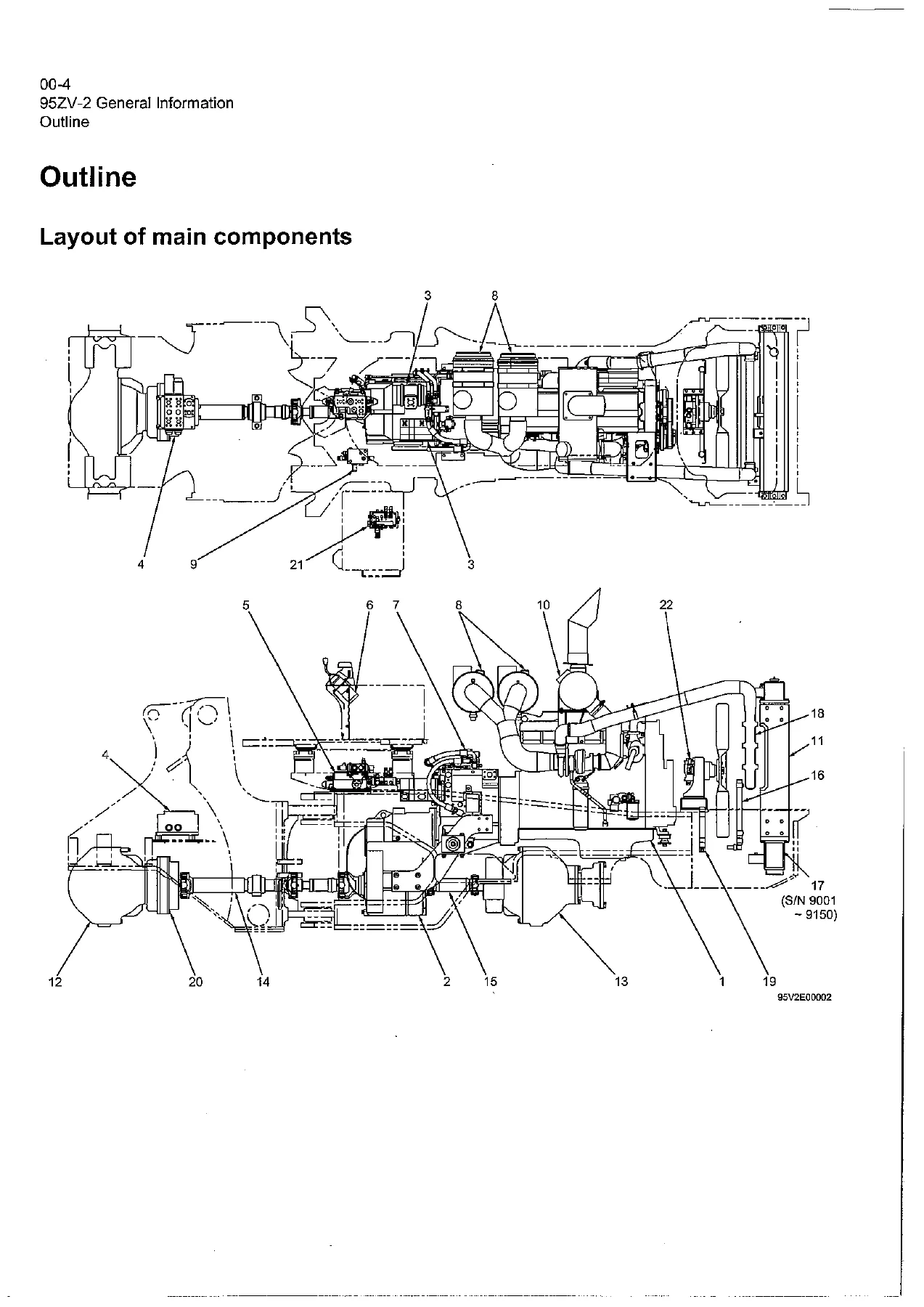
Safety procedures, hazard symbols, and how-to-use guidance for the manual. Includes the machine outline with a full layout of main components, the inspection and maintenance table with operating-hour intervals, recommended lubricants and capacities, coolant specifications and antifreeze mixture ratios, a lubrication chart, weights of main components, metric and unified bolt tightening torques, hose band tightening torques, and a list of liquid gasket and screw lock agents. Also covers cautions for welding repair service and battery/ECM handling.
Measurement for Performance Check
Standard measurement values used for performance testing: engine speeds (low idle, high idle, torque converter stall, relief mode), transmission main and clutch pressures, clutch time lag, cylinder drift rates, boom rising time, full steering time, relief valve setting pressures for loading and steering lines, pilot line reducing pressure, fan maximum revolution thresholds, service and parking brake performance checks, brake line setting pressures, accumulator charge time, and declutch engagement distances. All values are given for both normal and fuel-efficient operating modes.
Chassis Group
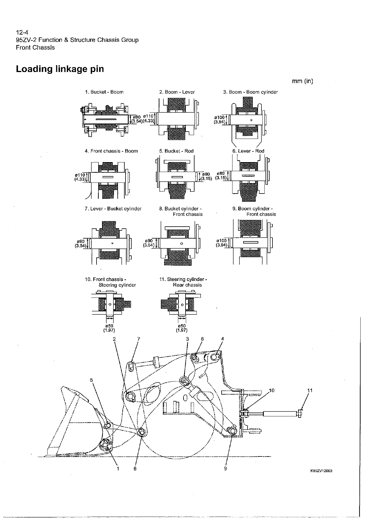
Front chassis construction with the full loading linkage — bucket, boom, link, lever, and cylinder arrangements. Covers linkage pin dimensions and locations, bucket roll-back and dump stopper adjustment, and the rear chassis including the fuel tank, floor board mounts with viscous damping, and the center pin assemblies (upper and lower) with bearing, shim, and dust seal details. The Check & Adjustment section gives liner and shim adjustment procedures for linkage pins, clearance specifications, bearing outer ring installation, grease nipple orientation, and center pin shim adjustment values.
Power Group
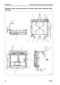
Complete power line from the Cummins QSX-15 engine through the torque converter and transmission to the second and third propeller shafts and the front and rear axles. Includes engine and transmission mounting, radiator assemblies for both serial ranges (9001-9150 and 9151-on), propeller shaft phase and alignment procedures, axle assembly with planetary gears and brakes, axle support, and the torque proportioning type differential gear (TPD) with its function, operation, and bias ratio. Also covers the optional Limited Slip Differential (LSD) with structure, function, and performance comparison against TPD. The Check & Adjustment section includes engine speed measurement, oil pressure testing, propeller shaft phase alignment, tightening torques, axle nut preload procedure, and differential gear adjustment including tooth contact patterns.
Torque Converter and Transmission Group
Torque converter structure, power flow path, and torque multiplication. Covers the optional lock-up clutch with structure and function, the torque converter gear pump with specifications, and the full transmission with clutch combinations, planetary gear sets, shift lever positions, downshift button operation, and gear train tooth counts. Includes detailed power flow paths for forward 1st through 4th speeds and reverse 1st through 3rd speeds. Hydraulic system diagrams, circuit diagrams, and oil flow paths are provided, along with the modulator valve unit, control valve assembly, check valve, clutch solenoid valve assembly, and clutch valve assembly. The Check & Adjustment section covers clutch oil pressure measurement and clutch time lag measurement with standard values and troubleshooting for low pressure or excessive lag.
Hydraulic Group
Flushing procedure for the hydraulic circuit, cautions on hydraulic parts replacement, and a complete set of hydraulic circuit symbols. Covers the hydraulic system operation outline for the loading system, steering system, efficient loading system (ELS), fan motor system, and ride control system (optional). Detailed sections on the hydraulic tank (both early and later designs), hydraulic pumps with wear plate and bushing lubrication details, hydraulic cylinders with specifications, the loading system, reducing valves, pilot valve (three serial ranges: 9001-9250, 9251-9255, 9256-on), multiple control valve (KML35A/2T003B) with spool operations and relief valves, ride control (optional), steering system, Orbitrol®, steering valve, stop valve, K-Lever (optional), efficient loading system, fan motor system, reversing fan motor line (optional), and secondary steering. The Check & Adjustment section provides relief valve and reducing valve setting pressures, cylinder natural drift limits, and stop valve adjustment.
Brake Group
Brake system outline covering service brake, parking brake, and axle internal pressure adjustment. Includes the brake units layout, unloader valve operation, valve unit, accumulator, brake valve performance chart and outline, service brake operation with friction plate, steel plate and piston details, service brake pedal stroke adjusting mechanism (S/N 9001-9014), brake circuit air bleeding procedure, parking brake operation with friction plate, steel plate and solenoid valve details, parking brake manual release, brake circuit check valve, and the auto brake system with circuit, operation set values, solenoid valve, and pressure sensors for stop lamp and declutch. Check & Adjustment covers brake circuit oil pressure, unloader valve setting pressure, brake valve oil pressure, service brake performance check, friction plate wear measurement, brake disc installation cautions, and parking brake performance check.
Electrical Group
How to use the electrical wiring diagram (with instructions also provided in French, German, Italian, Spanish, and Portuguese), electrical cable color codes, circuit symbols, sensor mounts, fuse and fuse box locations, fusible links, engine start circuit, neutral starter, starter switch, battery relay, alternator terminal wiring, diode unit, neutral relay, magnetic switch, voltage relay, power generating and charging circuit, alternator, ECM (Engine Controller) with function, connection diagram, monitor lamp test, failure diagnosis and Quantum fault code information, accelerator pedal, transmission control circuit and monitor circuit, machine control unit (MCU) with connection diagram, adjustable declutch preset switch, monitoring system, operation monitor lamps, instrument panel and switches, gauges, MODM (Machine Operation Diagnostic Module) with all monitor modes, electrical detent circuit, bucket leveler, detent solenoid, lift kickout and lower kickout, sensor assembly, preset height adjustment, diodes, diode check method, and surge voltage suppression diodes.
Operator Station Group
Cabin, glass, wiper mount and motor, tilt case, column shaft, shift lever, and the complete air conditioner system covering Denso components, structure, cooling mechanism function, cooling circuit, electrical circuit, component functions, refrigerant charging, troubleshooting, lubricating oil quantity adjustment when components are replaced, air gap adjustment for the compressor magnetic clutch, compressor V-belt adjustment, and parts to be replaced periodically.
Drawings & Diagrams
Full-page reference drawings including axle assembly, torque converter and transmission, hydraulic and brake circuit diagrams for different serial ranges, brake circuit, electrical wiring diagrams in three parts for multiple serial ranges, electrical connection diagrams, cabin air conditioner wiring and circuit diagrams, equipment operation tables, electrical equipment layout, K-Lever layout, MODM operation outline, and MODM input/output monitor signal correspondence tables.
Why This Manual Matters
The Kawasaki 95ZV-2 is a heavy-duty wheel loader designed for demanding loading, hauling, and material handling work. Keeping it running correctly requires more than guesswork — it requires the exact procedures, torque values, pressure settings, and diagnostic sequences specified for the machine. This shop manual provides all of that in one document. From the Cummins QSX-15 engine and its mounting, through the torque converter, transmission, differentials, axles, brakes, hydraulics, and electrical system, every major system is covered with the level of detail needed by professional technicians and serious owner-operators.
Whether you are replacing a clutch pack, adjusting a relief valve, troubleshooting a brake circuit, diagnosing an electrical fault through the MODM, or rebuilding a hydraulic cylinder, having the correct procedures and specifications on hand reduces downtime, prevents costly mistakes, and helps ensure the machine goes back to work safely and correctly.
IMAGES PREVIEW
Instant PDF Delivery
This Kawasaki 95ZV-2 shop manual is delivered as an instant PDF download — no shipping, no waiting, no physical media. After purchase, you can download the file immediately and access it on any device: desktop computer, laptop, tablet, or smartphone. Print the pages you need for the shop floor, or keep the entire manual on a tablet for quick reference during repairs.
Get the complete 95ZV-2 wheel loader repair manual today and have the information you need to service, maintain, and repair your machine correctly.
Reviews
There are no reviews yet.