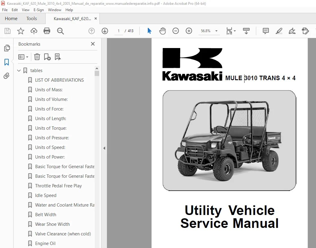
Kawasaki MULE 3010 TRANS 4 × 4 Vehicle Service Manual PDF
$29.95
Kawasaki MULE 3010 TRANS 4 × 4 Vehicle Service Manual – PDF DOWNLOAD
Description
Kawasaki MULE 3010 TRANS 4 × 4 Vehicle Service Manual – PDF DOWNLOAD
FILE DETAILS:
Kawasaki MULE 3010 TRANS 4 × 4 Vehicle Service Manual – PDF DOWNLOAD
Language : English
Pages : 413
Downloadable : Yes
File Type : PDF
IMAGES PREVIEW OF THE MANUAL:
![]()
![]()
TABLE OF CONTENTS:
Kawasaki MULE 3010 TRANS 4 × 4 Vehicle Service Manual – PDF DOWNLOAD
tables 1
LIST OF ABBREVIATIONS 6
Units of Mass: 21
Units of Volume: 21
Units of Force: 21
Units of Length: 21
Units of Torque: 21
Units of Pressure: 21
Units of Speed: 21
Units of Power: 21
Basic Torque for General Fasteners of Engine Parts 29
Basic Torque for General Fasteners of Frame Parts 29
Throttle Pedal Free Play 33
Idle Speed 34
Water and Coolant Mixture Ratio (Recommended) 39
Belt Width 40
Wear Shoe Width 41
Valve Clearance (when cold) 43
Engine Oil 44
Transmission Oil 46
Tire Tread Depth 47
Standard Tire 47
Front Final Gear Case Oil 47
Brake Pedal Free Play 49
Brake Drum Inside Diameter 52
Brake Shoe Lining Thickness 52
Parking Brake Lever Travel 55
Steering Wheel Free Play 56
Brake Light Switch Timing 57
Spark Plug Gap 57
Throttle Link Lever Bolt/Shim Clearance 73
Shims 73
Choke Cable Free Play 74
Valve Closing Temperature (for reference) 81
Water Pump Shaft Diameter 98
Water Pump Shaft Bearing Inside Diameter 98
Radiator Cap Relief Pressure 101
Thermostat Valve Opening Temperature 103
Cylinder Compression 112
Cylinder Head Warp 116
Valve Seating Surface Outside Diameter 117
Valve Seating Surface Width 117
Valve Spring Free Length 121
Valve Head Thickness 121
Valve Stem Bend 121
Valve Stem Diameter 121
Valve Guide Inside Diameter 122
Valve/Guide Clearance (Wobble Method) 122
Rocker Shaft Diameter 122
Rocker Arm Inside Diameter 123
Rocker Arm Push Rod Runout 123
Belt Deflection 139
Spacers 139
Spider Wear Guide Clearance 142
Cover Bushing Inside Diameter [A] 143
Sheave Bushing Inside Diameter [B] 143
Spider Wear Guide Thickness [B] 143
Spring Free Length [A] 144
Sheave Bushing Inside Diameter 147
Spring Free Length [A] 148
Inner Rotor/Outer Rotor Clearance 159
Inner Rotor Shaft Diameter [A] 159
Outer Rotor Diameter [B] 159
Outer Rotor Width [C] 159
Inner Rotor Shaft Bearing Inside Diameter [A] 160
Outer Rotor Housing Inside Diameter [B] 160
Rotor Housing Depth [C] 160
Cam Height (Inlet) 176
Cam Height (Exhaust) 176
Camshaft Journal Diameter 177
Camshaft Bearing Inside Diameter 177
Piston Ring/Groove Clearance (Top, Second) 181
Piston Ring End Gap (Top, Second) 181
Cylinder Inside Diameter 181
Piston Diameter 181
Oversize Piston and Rings 182
Connecting Rod Bend 183
Connecting Rod Twist 184
Connecting Rod Big End Side Clearance 184
Connecting Rod Big End Bearing/Crankpin Clearance 185
Crankpin Diameter 185
Connecting Rod Big End Inside Diameter 185
Crankshaft Runout 185
Crankshaft Main Journal Diameter 186
Crankshaft Main Bearing Inside Diameter 186
Shift Arm Pin Diameter [A] 207
Shifter Block Inside Diameter [B] 207
Shifter Block Outside Diameter [C] 207
Shifter Groove Width [D] 207
Drive Chain 20-Link Length [B] 207
Shifter Block Outside Diameter [A] 210
Shifter Groove Width [B] 210
Shifter Block Outside Diameter 213
Shifter Groove Width 213
Shift Arm Pin Diameter [A] 215
Shifter Groove Width [B] 215
Toe-in of Front Wheels 225
Maximum Tire Air Pressure (to seat beads when cold) 229
Tire Air Pressure (when cold) 230
LSD Clutch Torque 242
Outside Friction Plate Thickness 243
Inside Friction Plate Thickness 243
Using Spring Scale 247
Using Torque Wrench 247
Bevel Gear Backlash 248
Bevel Gear Backlash 254
Recommended Brake Fluid 276
Drum Press-fitting Force (Torque) 281
Spring Action 296
Tie- rod Length (distance between boot end and locknut) 311
Kawasaki-recommended chargers 353
Battery Terminal Voltage 355
Terminal Voltage: 11 5 ∼ less than 12 5 V 355
Terminal Voltage: less than 11 5 V 355
Regulator/Rectifier Output Voltage 359
Stator Coil Resistance 360
Ignition Coil Winding Resistance 364
Ignition Coil Primary Peak Voltage 365
Pickup Coil Resistance 365
Connections 366
Pickup Coil Peak Voltage 366
Carbon Brush Length 372
Commutator Diameter 373
Testing Switch 373
Testing Relay 374
Fuel Pump Leads 376
Fuel Pump Relay Internal Resistance (Tester Range: × 1 kΩ) 376
Radiator Fan Motor Leads 378
Radiator Fan Switch Resistance 382
Coolant Temperature Warning Light Switch Resistance 383
toc 1
Read OWNER’S MANUAL before operating 6
EMISSION CONTROL INFORMATION 7
1 7
2 7
PLEASE DO NOT TAMPER WITH NOISE CONTROL SYSTEM (US Model only) 8
Foreword 9
General Information 11
Before starting to perform an inspection service or carry out a 12
Battery Ground 12
Edges of Parts 12
Solvent 12
Cleaning vehicle before disassembly 12
Arrangement and Cleaning of Removed Parts 13
Storage of Removed Parts 13
Inspection 13
Replacement Parts 13
Assembly Order 13
Tightening Sequence 14
Tightening Torque 14
Force 14
Gasket, O-ring 14
Liquid Gasket, Locking Agent 14
Press 15
Ball Bearing and Needle Bearing 15
Oil Seal, Grease Seal 15
Circlips, Cotter Pins 15
Lubrication 16
Direction of Engine Rotation 16
Electrical Wires 16
KAF620-J1 Left Side View 17
KAF620-J1 Right Side View 17
Prefixes for Units: 21
Units of Temperature: 21
Periodic Maintenance 23
The scheduled maintenance must be done in accordance with this c 24
The following tables list the tightening torque for the major fa 26
Inside Circlip Pliers: 32
Fuel System 33
Throttle Pedal Free Play Inspection 33
Throttle Pedal Free Play Adjustment 33
Full Throttle Pedal Position Adjustment 34
Idle Speed Inspection 34
Idle Speed Adjustment 34
Fuel System Cleanliness Inspection 34
Fuel Filter Inspection 35
Intake Chamber Water Draining 35
External Carburetor Mechanism Cleaning 35
Fuel Hoses And Connections Inspection 35
Fuel Hoses Replacement 36
Air Cleaner Element Cleaning 36
Air Cleaner Housing Dust and/or Water Inspection 37
Cooling System 37
Radiator Cleaning 37
Radiator Hose and Connection Inspection 38
Coolant Draining 38
Coolant Filling 39
Torque – 39
Coolant Filter Inspection 40
Converter System 40
Drive Belt Inspection 40
Converter Driven Pulley Shoe Inspection 41
Air Cleaner Element Cleaning/Inspection 41
Converter Dust or Water Draining 42
Engine Top End 42
Valve Clearance Inspection 42
Valve Clearance Adjustment 43
Special Tool – 43
Torque – 43
Spark Arrester Cleaning 44
Engine Lubrication 44
Oil and/or Filter Change 44
Torque – 44
Oil Filter Removal 45
Special Tool – 45
Oil Filter Installation 45
Transmission 46
Transmission Oil Change 46
Torque – 46
Wheels/Tires 46
Wheels Nuts Tightness Inspection 46
Torque – 46
Tire Inspection 47
Final Drive 47
Front Final Gear Case Oil Change 47
Torque – 47
Torque – 47
Brakes 48
Brake Fluid Level Inspection 48
Brake Fluid Changing 49
Torque – 49
Brake Pedal Free Play Adjustment 49
Torque – 50
Brake Master Cylinder Cup and Dust Seal Replacement 50
Special Tool – 50
Torque – 50
Brake Hose and Pipe Inspection 51
Brake Hose and Pipe Replacement 51
Torque – 51
Brake Wear Inspection 52
Brake Wheel Cylinder Assembly Replacement 53
Torque – 54
Parking Brake Lever Travel Adjustment 55
Steering 56
Steering Wheel Free Play Inspection 56
Steering Joint Dust Boot Inspection 56
Frame 56
Seat Belt Inspection 56
Electrical System 57
Brake Light Switch Adjustment 57
Spark Plug Cleaning/Inspection 57
Spark Plug Gap Inspection 57
General Lubrication 57
Pivots and Points: Lubricate with Grease 58
Cables: Lubricate with Rust Inhibitor 58
Cables: Lubricate with Motor Oil 58
Bolts, Nuts, and Fasteners 59
Tightness Inspection 59
Nut, Bolt, and Fasteners to be checked 59
Fuel System 61
Throttle Pedal Free Play Inspection 67
Throttle Pedal Free Play Adjustment 67
Full Throttle Pedal Position Adjustment 67
Throttle Cable Installation 67
Throttle Cable Lubrication 67
Throttle Cable Inspection 67
Control Panel Assembly Removal 68
Control Panel Assembly Installation 68
Governor Arm and Throttle Link Removal 71
Governor Arm Installation 71
Torque – 71
Governor Assembly Removal 72
Governor Assembly Installation 72
Governor Assembly Inspection 72
Throttle Link Lever Installation 73
Torque – 73
Maximum Engine Speed Inspection 73
Choke Cable Free Play Inspection 74
Choke Cable Free Play Adjustment 74
Choke Cable Installation 74
Choke Cable Lubrication 74
Choke Cable Inspection 75
Idle Speed Inspection 76
Idle Speed Adjustment 76
Fuel System Cleanliness Inspection 76
Carburetor Removal 76
Carburetor Installation 77
Torque – 77
Torque – 78
Sealant – 78
Torque – 78
Carburetor Disassembly 78
Carburetor Assembly 79
Torque – 79
Carburetor Cleaning 80
Carburetor Inspection 80
Coolant Filter Cleaning 81
Coolant Valve Inspection 81
Air Cleaner Element Cleaning 82
Air Cleaner Housing Removal 82
Air Cleaner Housing Installation 82
Torque – 82
Sealant – 82
Torque – 82
Air Cleaner Housing Dust and/or Water Inspection 82
Fuel Pump and Fuel Filter Removal 83
Fuel Pump Installation 83
Fuel Filter Installation 83
Fuel Filter Inspection 83
Fuel Tank Removal 84
Fuel Tank Installation 85
Fuel Tank Cleaning/Inspection 85
Cooling System 87
Kawasaki Bond (Silicone Sealant): 91
Coolant Level Inspection 95
Coolant Draining 95
Coolant Filling 95
Pressure Testing 95
Water Pump Removal 96
Water Pump Installation 97
Torque – 97
Water Pump Inspection 98
Radiator Removal 99
Radiator Inspection 100
Radiator Cleaning 100
The radiator cap at the reservoir tank has the pressure relief v 101
Radiator Cap Inspection 101
Thermostat Removal 102
Thermostat Installation 102
Thermostat Inspection 102
Hose and Pipe Installation 104
Hose Inspection 104
Radiator Fan Switch, Coolant Temperature Warning Light Switch Re 105
Radiator Fan Switch, Coolant Temperature Warning Light Switch In 105
Sealant – 105
Torque – 105
Radiator Fan Switch, Coolant Temperature Warning Light Switch In 105
Engine Top End 107
Outside Circlip Pliers: 111
Cylinder Compression Measurement 112
Cylinder Head Removal 112
Cylinder Head Installation 114
Torque – 115
Torque – 115
Cylinder Head Disassembly and Assembly (Valve Mechanism Removal 115
Special Tool – 115
Cylinder Head Warp 116
Valve Clearance Inspection 117
Valve Clearance Adjustment 117
Valve Seat Inspection 117
Valve Seat Repair 117
Special Tools – 117
Special Tools – 118
Valve Spring Free Length 121
Valve Head Thickness 121
Valve Stem Bend 121
Valve Stem Diameter 121
Valve Guide Inside Diameter 122
Measuring Valve/Guide Clearance (Wobble Method) 122
Rocker Arm/Shaft Wear 122
Rocker Arm Push Rod Inspection 123
Exhaust Pipe Removal 124
Muffler Removal 124
Exhaust Pipe and Muffler Installation 124
Exhaust Pipe and Muffler Inspection 125
Spark Arrester Cleaning 125
Converter System 127
Outside Circlip Pliers: 133
Air Cleaner Housing Removal 134
Air Cleaner Element Removal 134
Air Cleaner Element Cleaning/Inspection 134
Torque Converter Removal 135
Special Tool – 135
Torque Converter Installation 136
Torque – 136
Torque – 137
Torque Converter Case Removal 137
Drive Belt Removal 138
Drive Belt Installation 138
Drive Belt Deflection Inspection 139
Drive Belt Deflection Adjustment 139
Torque – 139
Drive Belt Inspection 139
Drive Pulley Disassembly 140
Special Tool – 140
Special Tool – 140
Drive Pulley Assembly 141
Torque – 141
Special Tool – 142
Torque – 142
Torque – 142
Spider/Wear Guide Clearance Adjustment 142
Drive Pulley Inspection 142
Bushing Installation 144
Driven Pulley Disassembly 145
Special Tools – 145
Special Tool – 145
Driven Pulley Assembly 146
Torque – 146
Special Tools – 146
Special Tool – 147
Driven Pulley Inspection 147
Bushing Installation 148
Engine Lubrication System 149
Oil Filter Wrench: 153
WARNING 155
Oil Level Inspection 155
Oil and/or Filter Change 157
Oil Filter Removal 157
Oil Filter Installation 157
Oil Pump and Relief Valve Removal 158
Oil Pump and Relief Valve Installation 158
Oil Pump and Relief Valve Inspection 158
Oil Screen Removal 161
Oil Screen Installation 161
Oil Screen Cleaning/Inspection 161
Oil Pressure Switch Removal 162
Oil Pressure Switch Installation 162
Sealant – 162
Torque – 162
Engine Removal/Installation 163
Engine Removal 166
Engine Installation 167
Torque – 167
Engine Bottom End 169
Piston Pin Puller Assembly: 174
Crankcase Cover Removal 175
Crankcase Cover Installation 175
Torque – 175
Camshaft Removal 176
Camshaft Installation 176
Camshaft Inspection 176
Cam Wear 176
Camshaft Bearing/Journal Wear 177
Piston Removal 178
Special Tool – 178
Piston Installation 179
Special Tools – 180
Torque – 180
Piston Ring, Piston Ring Groove Wear 181
Piston Ring End Gap 181
Cylinder Inside Diameter 181
Piston Diameter 181
Boring, Honing 182
Connecting Rod Removal 183
Connecting Rod Installation 183
Crankshaft Removal 183
Crankshaft Installation 183
Crankshaft Cleaning 183
Connecting Rod Bend/Twist 183
Connecting Rod Big End Side Clearance 184
Connecting Rod Big End Bearing/Crankpin Wear 184
Torque – 184
Torque – 185
Crankshaft Runout 185
Crankshaft Main Bearing/Journal Wear 186
Breather Valve Removal 187
Breather Valve Installation 187
Breather Valve Inspection 187
Transmission 189
Outside Circlip Pliers: 197
CAUTION 198
Transmission Oil Level Inspection 198
Transmission Oil Change 198
Transmission Case Removal 199
Transmission Case Installation 199
Torque – 199
Transmission Case Splitting 200
Transmission Case Assembly 200
Sealant – 200
Torque – 200
Transmission and Hi/Low Shift Cables Installation 201
Shift Lever Position Inspection 204
Shift Lever Position Adjustment 204
Transmission Shift Cable Inspection 205
Transmission Removal 205
Special Tool – 205
Special Tool – 206
Transmission Installation 206
Torque – 206
Transmission and Shift Mechanism Inspection 207
Hi/Low Shift Cable Installation 208
Hi/Low Shift Cable Inspection 208
Hi/Low Gear and Shift Mechanism Removal 208
Special Tool – 209
Hi/Low Gear and Shift Mechanism Installation 209
Torque – 210
Hi/Low Gear and Shift Mechanism Inspection 210
2WD/4WD Shift Cable Adjustment 211
2WD/4WD Shift Cable Lubrication 212
2WD/4WD Shift Cable Inspection 212
2WD/4WD Shift Mechanism Removal 212
Special Tool – 213
2WD/4WD Shift Mechanism Installation 213
Torque – 213
2WD/4WD Shift Mechanism Inspection 213
Differential Shift Cable Adjustment 214
Differential Shift Cable Lubrication 214
Differential Shift Cable Inspection 214
Differential Shift Mechanism Removal 214
Differential Shift Mechanism Installation 215
Torque – 215
Differential Shift Mechanism Inspection 215
Differential Gear Removal 215
Differential Gear Installation 216
Torque – 216
Differential Gear Inspection 216
Bearing Replacement 217
Special Tools – 217
Special Tool – 217
Torque – 217
Special Tool – 217
Ball Bearing Inspection 217
Needle Bearing Inspection 217
Oil Seal Inspection 217
Wheels/Tires 221
Toe-in is the amount that the front wheels are closer together i 225
Toe-in Adjustment 225
Torque – 226
Wheel Removal 227
Wheel Installation 227
Torque – 227
Wheel (Rim) Inspection 227
Wheel (Rim) Replacement 227
Tire Removal 229
Tire Installation 229
Tire Inspection 230
Final Drive 231
Bearing Puller: 237
Front Final Gear Case Oil Level Inspection 238
Torque – 238
Front Final Gear Case Oil Change 238
Front Final Gear Case Removal 239
Front Final Gear Case Installation 239
Torque – 239
Front Final Gear Case Disassembly 240
Front Final Gear Case Assembly 240
Torque – 241
Differential Unit and Ring Gear Disassembly 241
Differential Unit and Ring Gear Assembly 241
Torque – 242
LSD Clutch Torque Inspection 242
LSD Clutch Plate Inspection 243
Pinion Gear Unit Disassembly 243
Special Tools – 243
Special Tool – 243
Pinion Gear Unit Assembly 243
Torque – 244
Front Final Bevel Gear Adjustment 244
Special Tool – 247
Special Tool – 247
Special Tool – 248
Special Tool – 248
Bevel Gear Inspection 250
Differential Gear Inspection 250
Tapered Roller Bearing Inspection 250
Ball Bearing Inspection 250
Oil Seal Inspection 250
Bevel Gear Case Removal 251
Bevel Gear Case Installation 251
Torque – 251
Bevel Gear Case Disassembly 251
Special Tools – 251
Special Tools – 252
Special Tool – 252
Special Tool – 252
Special Tools – 252
Bevel Gear Case Assembly 252
Torque – 252
Drive Bevel Gear Removal 253
Special Tool – 253
Drive Bevel Gear Installation 253
Torque – 253
Bevel Gear Adjustment 253
Special Tool – 254
Bevel Gear Inspection 257
Ball Bearing Inspection 257
Oil Seal Inspection 257
Damper Inspection 257
Propeller Shaft Removal 258
Propeller Shaft Installation 259
Propeller Shaft Inspection 260
Front Axle Removal 261
Front Axle Installation 261
Torque – 261
Rear Drive Shaft and Axle Removal 261
Rear Drive Shaft and Axle Installation 262
Drive Shaft and Axle Inspection 262
Dust Boot Inspection 263
Front Axle Joint Boot Replacement 263
Special Tool – 263
Special Tool – 264
Special Tool – 266
Ball Bearing Inspection 267
Grease Seal Inspection 268
Brakes 269
Inside Circlip Pliers: 275
Brake Fluid Recommendation 276
Brake Fluid Level Inspection 276
Brake Fluid Changing 276
Brake Line Air Bleeding 277
Torque – 277
Brake Pedal Free Play Adjustment 278
Master Cylinder Removal 278
Master Cylinder Installation 278
Torque – 278
Master Cylinder Disassembly 278
Master Cylinder Assembly 278
Master Cylinder Inspection 279
Brake Hose and Pipe Inspection 280
Brake Hose and Pipe Replacement 280
Brake Drum Removal 281
Special Tools – 281
Brake Drum Installation 281
Special Tools – 281
Torque – 282
Brake Drum Wear 282
Brake Panel Removal 283
Brake Panel Installation 284
Torque – 285
Wheel Cylinder Assembly 286
Wheel Cylinder Inspection 286
Brake Shoe Lining Wear 286
Brake Shoe Spring Inspection 287
Parking Brake Lever Travel Adjustment 288
Parking Brake Cable Lubrication 288
Parking Brake Cable Inspection 288
Suspension 289
Steering Stem Nut Wrench: 293
Strut (Front Shock Absorber) Removal 294
Strut (Front Shock Absorber) Installation 294
Torque – 294
Strut Spring Replacement 295
Torque – 296
Rear Shock Absorber Preload Adjustment 296
Special Tool – 296
Rear Shock Absorber Removal 297
Rear Shock Absorber Installation 297
Torque – 297
Shock Absorber Inspection 297
Front Suspension Arm Removal 298
Front Suspension Arm Installation 298
Torque – 298
Front Suspension Arm Inspection 299
Leaf Spring Removal 300
Leaf Spring Installation 300
Torque – 300
Torque – 300
Leaf Spring Inspection 301
Steering 303
Steering Wheel Position Adjustment 307
Steering Wheel Free Play Inspection 307
Steering Wheel Centering 307
Torque – 307
Steering Wheel and Steering Shaft Removal 307
Steering Wheel and Main Shaft Installation 308
Torque – 308
Steering Gear Assembly Removal 309
Steering Gear Assembly Installation 309
Torque – 310
Steering Gear Preload Adjustment 310
Torque – 310
Tie-rod Length Adjustment 311
Torque – 311
Steering Joint Dust Boot Inspection 311
Steering Knuckle Removal 312
Steering Knuckle Installation 312
Torque – 312
Frame 315
Front Seat Removal 322
Front Seat Installation 322
Rear Seat Removal 323
Rear Seat Installation 324
Seat Belt Removal 324
Seat Belt Installation 325
Torque – 325
Torque – 325
Control Panel Removal 326
Glove Compartment Removal 326
Front Cargo Hood Removal 327
Front Cargo Compartment Removal 327
Cargo Bed Removal 328
Cargo Bed Installation 329
Front Bar Removal 330
Front Bar Installation 330
Torque – 330
Rear Bar Removal 330
Rear Bar Installation 331
Torque – 331
Center Bar Removal 331
Center Bar Installation 331
Torque – 331
Cargo Bed Latch Position Inspection 332
Cargo Bed Latch Position Adjustment 332
Front Cover Removal 333
Front Fender Removal 334
Radiator Side Cover Removal 334
Radiator Side Cover Installation 335
Radiator Side Cover Flap Removal 335
Floor Center Panel Removal 335
Rear End Sub-frame Removal 337
Rear End Sub-frame Installation 337
Torque – 337
Electrical System 339
Crankcase Splitting Tool Assembly: 345
Horn [A] 346
There are a number of important precautions that are musts when 349
Battery Removal 351
Battery Installation 351
Torque – 352
Battery Activation 352
Precautions 354
1) 354
2) 354
3) 354
4) 354
Interchange 354
Charging Condition Inspection 355
Refreshing Charge 355
Alternator Rotor and Stator Removal 357
Special Tool – 357
Alternator Rotor and Stator Installation 358
Torque – 358
Charging System Operational Inspection 359
Stator Coil Resistance 360
Regulator/Rectifier Inspection 360
Charging System Circuit 362
WARNING 363
Spark Plug Removal/Installation 363
Torque – 363
Spark Plug Gap Inspection 363
Spark Plug Cleaning/Inspection 363
Ignition Coil Removal 363
Ignition Coil Installation 364
Ignition Coil Inspection 364
Ignition Coil Primary Peak Voltage Inspection 364
Special Tools – 364
Pickup Coil Removal 365
Pickup Coil Inspection 365
Pickup Coil Peak Voltage Inspection 366
Special Tool – 366
Ignition System Inspection 367
Ignition System Circuit 368
Starter Motor Removal 369
Starter Motor Installation 369
Torque – 369
Starter Motor Disassembly 369
Starter Motor Assembly 371
Carbon Brush Inspection 372
Yoke Inspection 372
Brush Plate Inspection 372
Commutator Cleaning/Inspection 372
Armature Inspection 373
Pinion Gear Inspection 373
Starter Switch Inspection 373
Starter Circuit Relay Inspection 374
Electric Starter Circuit 375
The fuel pump does not operate when the ignition switch is turne 376
Fuel Pump Operational Inspection 376
Fuel Pump Relay Internal Resistance 376
Fuel Pump and Relay Circuit 377
Radiator Fan Circuit Inspection 378
Radiator Fan Motor Inspection 378
Radiator Fan Circuit 378
Headlight Beam Adjustment 379
Headlight Bulb Replacement 379
Tail/Brake Light Replacement 380
Lighting System Circuit 381
Brake Light Switch Adjustment 382
Switch Inspection 382
Radiator Fan Switch Inspection 382
Coolant Temperature Warning Light Switch Inspection 383
Fuse Removal 384
Fuse Installation 384
Fuse Inspection 384
Wiring Inspection 385
Appendix 389
NOTE 390
Engine Doesn’t Start, Starting Difficulty: 390
Starter motor not rotating: 390
Starter motor rotating but engine doesn’t turn over: 390
Engine won’t turn over: 390
No fuel flow: 390
Engine flooded: 390
No spark; spark weak: 390
Compression Low: 390
Poor Running at Low Speed: 390
Spark weak: 390
Fuel/air mixture incorrect: 390
Compression low: 390
Other: 390
Poor Running or No Power at High Speed: 391
Firing incorrect: 391
Fuel/air mixture incorrect: 391
Compression low: 391
Knocking: 391
Miscellaneous: 391
Overheating: 391
Firing incorrect: 391
Fuel/air mixture incorrect: 391
Compression high: 391
Engine load faulty: 391
Converter and/or belt excessive heating: 391
Lubrication inadequate: 391
Front final gear case overheating: 391
Coolant incorrect: 391
Cooling system component incorrect: 391
Over Cooling 391
Converter Operation Faulty: 391
Belt slipping: 391
Converter engagement speed too low: 391
Converter engagement speed too high: 391
Shifting too quickly: 392
Shifting too slowly: 392
Gear Shifting Faulty: 392
Doesn’t go into gear: 392
Jumps out of gear: 392
Overshifts: 392
Abnormal Engine Noise: 392
Knocking: 392
Piston slap: 392
Valve noise: 392
Other noise: 392
Abnormal Drive Train Noise: 392
Converter noise: 392
Transmission noise: 392
Final drive noise: 392
Abnormal Frame Noise: 392
Shock absorber noise: 392
Brake noise: 392
Other noise: 392
Exhaust Smokes Excessively: 392
White smoke: 392
Black smoke: 392
Brown smoke: 393
Handling and/or Stability Unsatisfactory: 393
Steering wheel hard to turn: 393
Noise when turning: 393
Steering wheel shakes or excessively vibrates: 393
Steering wheel pulls to one side: 393
Shock absorption unsatisfactory: 393
Brake Doesn’t Hold 393
Battery Discharged: 393
Battery Overcharged: 393
DESCRIPTION:
Kawasaki MULE 3010 TRANS 4 × 4 Vehicle Service Manual – PDF DOWNLOAD
FOREWORD:
- This manual is designed primarily for use by trained mechanics in a properly equipped shop. However, it contains enough detail and basic information to make it useful to the owner who desires to perform his own basic maintenance andrepair work. A basic knowledge of mechanics, the proper use of tools, and workshop procedures must be understood in order to carry outmaintenance and repair satisfactorily. Whenever the owner has insufficient experience or doubts his ability to do the work, all adjustments, maintenance, and repair should be carried out only by qualified mechanics.
- In order to perform the work efficiently and to avoid costly mistakes, read the text, thoroughly familiarize yourself with the procedures before starting work, and then do the work carefullyin a clean area. Whenever special tools or equipment are specified, do not use makeshift tools or equipment. Precision measurements can only be made if the proper instruments are used, and the use of substitute tools may adversely affect safe operation.
- For the duration of the warranty period, we recommend that all repairs and scheduled maintenance be performed in accordance with this servicemanual. Any owner maintenance or repair procedure not performed in accordance with this manual may void the warranty.
To get the longest life out of your vehicle:
S.V 16/03/2025