Kawasaki WHEEL LOADER 135ZV-2 SHOP MANUAL 93217-00111 – PDF DOWNLOAD
$29.95
Kawasaki WHEEL LOADER 135ZV-2 SHOP MANUAL 93217-00111 – PDF DOWNLOAD
General Information
Standard Measurement Values for Performance Check
Function & Structure Check & Adjustment
Description
Kawasaki WHEEL LOADER 135ZV-2 SHOP MANUAL 93217-00111 – PDF DOWNLOAD
FILE DETAILS:
Kawasaki WHEEL LOADER 135ZV-2 SHOP MANUAL 93217-00111 – PDF DOWNLOAD
Language :English
Pages :465
Downloadable : Yes
File Type : PDF
IMAGES PREVIEW OF THE MANUAL:
DESCRIPTION:
Kawasaki WHEEL LOADER 135ZV-2 SHOP MANUAL 93217-00111 – PDF DOWNLOAD
General Information
Standard Measurement Values for Performance Check
Function & Structure Check & Adjustment
- To ensure good machine performance, reduce failures or problems, and prolong the service life of
each component, it is necessary to operate the machine as is directed in the Operator and
Maintenance Manual. - To effectively diagnose and repair the machine, it is important to follow the guidelines laid out
in this Shop Manual.
For the engine, refer to the engine Shop Manual provided by the engine manufacturer.
- The purpose of this manual is to provide information on the product and the correct maintenance and
repair meth- ods. Please read this manual to ensure correct troubleshooting and good repair
service. - This manual will be periodically reviewed and revised for more satisfactory content. If
you have any opinion or requests, please inform us. - Safety Symbols
- An accident may occur if you disregard safety rules. In this manual, several expressions are used according to levels of danger for inspection and repair work as shown below. Read the work procedures and cautions described in this manual, and
take preventive measures against possible problems before starting service work. - We cannot predict all possible accidents or incidents that may occur during service work. Therefore, an accident that is not specifically mentioned in this manual may occur. To protect yourself from all accidents, be careful when doing service work.
TABLE OF CONTENTS:
Kawasaki WHEEL LOADER 135ZV-2 SHOP MANUAL 93217-00111 – PDF DOWNLOAD
General Information
Standard Measurement Values for Performance Check
Function & Structure Check & Adjustment
Safety Symbols 5
CONTENTS 6
00 General Information 16
How to Use Manual 17
Safety precautions 17
Symbols 18
Outline 19
Layout of main components 19
Inspection and maintenance table 20
Recommended lubricants 23
Coolant 24
Coolant specification 24
Recommended mixture of antifreeze 24
Lubrication chart 25
Weight of main components 26
Bolt tightening torque 27
Hexagon bolt 27
Flanged hexagon bolt 30
Hose band tightening torque 31
Liquid gasket and screw lock agent 32
Cautions regarding parts removal 32
Cautions regarding reassembly 32
Screw lock agent application procedure 33
How to wind a seal tape 33
Cautions regarding welding repair service 34
Hydraulic Pressure Test Kit 36
03 Measurement for Performance Check 38
Cautions on Safety 39
Standard Measurement Values for Performance Check 40
12 Function & Structure Chassis Group 44
Front Chassis 45
Loading linkage 45
Loading linkage pin 47
Rear Chassis 48
Fuel tank 48
Floor board mount 49
Floor board 49
Viscous mount 49
Center Pin 50
Upper center pin 50
Lower center pin 51
Dust seal 52
13 Check & Adjustment Chassis Group 54
Linkage Pin 55
Liner 55
Bucket hinge pin section (#1) 56
How to assemble 56
Bucket link pin section (#2) 57
How to assemble 57
Adjustment 58
Center Pin 59
Adjusting shim 59
Installing bearing cover 59
Installing bearing outer ring 60
22 Function & Structure Power Group 62
Power Line 63
Engine / Transmission 64
Engine mount 64
Transmission mount 65
Radiator 66
Radiator mount 67
T/C cooler mount 68
Propeller Shaft 69
First propeller shaft assembly 70
Transmission – Torque converter 70
Second propeller shaft assembly 71
Front differential – Transmission 71
Third propeller shaft assembly 72
Transmission – Rear differential 72
Axle Assembly 73
Axle Support 75
Differential Gear 77
Conventional type 77
Function of differential gear 79
Power transmission 79
Operation of differential gear 79
Straight 79
Turn 80
23 Check & Adjustment Power Group 82
Engine 83
Measuring engine speed 83
Measuring engine oil pressure 83
Propeller Shaft 84
Propeller shaft phase 84
Second propeller shaft alignment 84
Tightening torque 85
Axle 86
Axle 86
Plate (29) installing procedure 86
Planetary gear oil drain and refill 87
Differential gear adjustment procedure 88
Preload adjustment 89
Bearing installation 89
Oil seal installation 89
Adjusting tooth contact 90
32 Function & Structure T/C and T/M Group 92
Torque Converter 93
Torque converter structure 94
Power flow path 94
Torque multiplication 94
Lock-up clutch function (only forward) 95
Automatic shift (with lock-up solenoid) 95
Shift up and shift down chart 95
Torque Converter Gear Pump 96
Gear pump specifications 96
Actual pump discharge L/min (GPM) 96
Transmission 97
Clutch combination 98
Planetary gear 98
Shift lever position 98
Downshift button operation 98
Gear train and number of teeth 99
Clutch specifications100
Friction plate: mm (in)100
Steel plate: mm (in)102
Clutch Pack104
Power Flow Path in the Transmission105
Forward 1st speed power flow path105
Forward 2nd speed power flow path106
Forward 3rd speed power flow path106
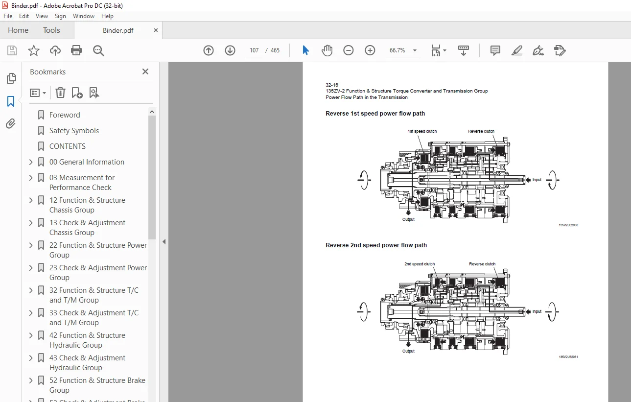
Reverse 1st speed power flow path107
Reverse 2nd speed power flow path107
Reverse 3rd speed power flow path108
Hydraulic System Diagram109
Hydraulic Circuit Diagram110
Oil Flow112
Oil flow in torque converter line112
From pump to torque converter112
From torque converter to cooling circuit112
From cooler to lubrication circuit112
Oil flow in transmission line112
From pump to lock-up clutch112
From pump to solenoid valve113
From pump to clutch valve113
From accumulator to clutch valve113
Pressure switch113
Priority & T/C relief valve114
T/C and T/M Oil Circulation115
Modulator Valve Unit116
Interior schematic (not exact representation)117
Modulation Mechanism118
Modulator valve function118
Modulator valve operation119
Control Valve Assembly120
Clutch solenoid valve assembly121
Clutch solenoid valve123
Clutch valve assembly124
Check valve assembly125
Lock-up clutch solenoid valve126
Accumulator assembly127
33 Check & Adjustment T/C and T/M Group128
Measuring Clutch Oil Pressure129
Priority valve adjusting procedure130
Adjusting procedure130
42 Function & Structure Hydraulic Group132
Flushing Hydraulic Circuit133
Purpose of flushing133
Cautions on Hydraulic Parts Replacement134
Hydraulic Circuit Symbols135
Hydraulic lines135
Pumps & motors135
Cylinders135
Operation methods136
Pressure control valve136
Flow control valve136
Directional control valve137
Check valve137
Miscellaneous hydraulic symbols138
Hydraulic System Operation139
Hydraulic system operation outline139
Loading system139
Steering system139
Efficient loading system140
Ride control system (OPT)140
Layout of Hydraulic Units141
Hydraulic Tank142
Hydraulic tank breather valve (tank cap)143
Hydraulic tank sub tank144
Hydraulic tank suction filter145
Suction filter specifications145
Hydraulic tank return filter146
Return filter specifications146
Hydraulic tank specifications147
Hydraulic oil level check148
Hydraulic Pump149
Steering pump (K3V)150
Steering pump (K3V) outline drawing150
Steering pump (K3V) specifications150
Steering pump (K3V) port150
Steering pump (K3V) main body151
Steering pump (K3V) major components152
Steering pump (K3V) operation152
Steering pump (K3V) rotary assembly152
Steering pump (K3V) diagonal (swash) plate assembly152
Steering pump (K3V) valve cover assembly153
Steering pump (K3V) regulator154
Steering pump (K3V) regulator structure154
Steering pump (K3V) regulator assembly155
Loading pump (K5V)156
Loading pump (K5V) outline drawing156
Loading pump (K5V) specifications156
Loading pump (K5V) port156
Triple pump157
Triple pump specifications157
Hydraulic pump principle158
Hydraulic pump wear plate159
Hydraulic pump bushing lubrication159
Hydraulic Cylinder160
Boom cylinder160
Bucket cylinder160
Steering cylinder161
Hydraulic cylinder specifications162
Loading System163
Reducing Valve (for Pilot Pressure)164
Pilot Valve (TH40MS)165
Pilot valve (TH40MS) function165
Pilot valve (TH40MS) Installation position detail166
Pilot valve (TH40MS) performance chart167
Pilot valve (TH40MS) structure168
Pilot valve (TH40MS) operation169
Boom soft landing circuit171
Boom soft landing hydraulic connection172
Procedure how to set boom soft landing173
Power boost circuit174
Steering unloader circuit175
Hydraulic line connection175
Steering unloader circuit structure176
Steering unloader circuit outline177
Steering unloader circuit function177
Solenoid valve178
Solenoid valve structure (Not activated)178
Solenoid valve operation178
Slow return check valve (Boom soft landing circuit)180
Slow return check valve (Boom soft landing circuit) specification180
Adapter (Orifice)181
Slow return check valve (Boom raise)182
Slow return check valve (Boom raise) specification182
Multiple Control Valve (KML35A/2T401A)183
Multiple control valve specifications184
Multiple control valve main relief valve (MRV) (2 stage relief)185
Multiple control valve main relief valve (MRV) operation186
Multiple control valve main relief valve (MRV) adjusting set pressure186
Multiple control valve overload relief valve (with make-up function)187
Multiple control valve overload relief valve operation187
Multiple control valve make-up valve188
Multiple control valve make-up valve operation188
Multiple control valve bucket spool189
Bucket spool operation189
Multiple control valve boom spool191
Boom spool operation191
Pilot valve194
Pilot valve structure195
Pilot valve operation196
Normal mode196
Regeneration mode196
Ride Control (OPT)197
Ride control hydraulic circuit198
Ride control function199
Ride control operation200
Preparation mode (ride control switch is OFF)200
Running mode (ride control switch is ON)201
Ride control valve assembly (Reducing valve circuit)202
Reducing valve203
Check valve203
Solenoid valve204
Ride control valve assembly (Accumulator circuit)205
Shuttle valve206
Solenoid valve206
Check valve207
Accumulator (for ride control)208
Accumulator function208
Accumulator specification208
Steering System209
Pilot Valve (for Steering)210
Pilot valve (for steering) operation211
Steering Valve (KVS32-A10/31)212
Steering valve operation214
Neutral position (steering spool in “Neutral”)214
Left turn position215
Steering spool variable throttle216
Steering valve flow control spool217
Steering valve main relief valve218
When the pressure is at the preset value or less218
When the pressure exceeds the preset value219
Steering valve overload relief valve220
Overload relief valve operation221
Make-up valve operation221
Steering pilot circuit and its operation222
Oil flow222
Stop Valve223
Stop valve operation224
Slow Return Check Valve225
Slow return check valve specifications226
Steering Lock Line227
Efficient Loading System228
Efficient loading system outline228
Operation condition of ELS229
Hydraulic line229
Mounting of the variable kickout sensor231
Lower kickout232
43 Check & Adjustment Hydraulic Group234
Loading/Steering Circuit Relief Valve235
Loading circuit relief valve setting pressures235
Measuring loading circuit main relief pressure236
Measuring loading circuit overload relief pressure238
Measuring pilot circuit reducing valve pressure239
Steering circuit relief valve setting pressures240
Measuring steering circuit main relief pressure241
Measuring steering circuit overload relief pressure242
Hydraulic Cylinder244
Cylinder natural drift244
Stop Valve246
Stop valve adjustment procedure246
52 Function & Structure Brake Group248
Brake System Outline249
Service brake249
Parking brake249
Auto brake249
Brake Units Layout250
Unloader Valve251
Unloader valve operation252
Valve Unit253
Reducing Valve (for Parking/Pilot Pressure/Power Boost)254
Accumulator low pressure sensor255
Accumulator256
Brake Valve257
Brake valve performance chart258
Brake valve outline259
While the valve is not operating259
While the valve is operating260
While the valve is releasing260
Line Filter261
Service Brake262
Service brake operation263
Service brake disc264
Friction plate264
Steel plate265
Service brake piston266
Service brake pedal stroke adjusting mechanism267
Caution on assembling the brake disc268
Tolerance ring269
Service brake warning system271
Detection of brake disc wear271
Detection of the oil temperature around the brake disc273
Brake circuit air bleeding procedure274
Bleeding air from brake pipes and axle housing hubs275
Parking Brake276
Parking brake operation277
Operation of parking brake278
Parking brake friction disc279
Friction plate279
Steel plate279
Parking brake solenoid valve280
Solenoid valve operation280
Solenoid valve specifications280
Parking Brake Manual Release281
Brake Circuit Check Valve282
Auto Brake283
Auto brake circuit283
Auto brake operation set value284
Reducing valve (for Autobrake circuit)285
Solenoid valve (for Autobrake circuit)286
Solenoid specifications286
Pressure Sensor (for stop lamp and declutch)287
Pressure sensor (for stop lamp)287
Pressure sensor (for Declutch)288
53 Check & Adjustment Brake Group290
Brake Circuit Oil Pressure291
Unloader valve setting pressure291
Unloader valve setting pressure measurement292
Brake valve oil pressure293
Brake valve oil pressure measurement293
Brake valve performance294
Service Brake295
Service brake performance check295
Service brake friction plate wear detection296
Detection of brake disc wear296
Parking Brake297
Parking brake performance check297
62 Function & Structure Electrical Group298
How to Use Electrical Wiring Diagram299
Electrical Cable Color Codes300
Electrical Circuit Symbols301
Sensor Mount302
Fuse304
Fuse box304
Fusible link305
Engine Start Circuit307
Engine start circuit diagram307
Neutral starter308
Shift lever neutral (N) position308
Shift lever forward/reverse (F/R) position308
Engine starting/stopping procedure308
Starter switch309
Battery relay310
Battery relay operation310
Alternator I terminal wire310
Diode unit311
Neutral relay312
Magnetic switch313
Voltage relay314
Power Generating/Charging Circuit315
Alternator315
ECM (Engine Controller)316
Function of ECM316
Connection diagram316
Monitor lamp test317
Failure diagnosis318
Engine diagnostic switch (option)318
Failure diagnostic chart319
Increment decrement switch (option)320
Quantum fault code information321
Accelerator pedal328
Accelerator pedal installation329
Transmission Control Circuit and Monitor Circuit330
Machine control unit (MCU)330
Connector331
MCU connection diagram332
Machine control unit (MCU) function334
Forward/reverse (F/R) shifting and speed change334
Automatic shift337
Machine speed sensor338
Downshift button operation339
Modulation at clutch switching340
Modulator valve operation342
Initial oil charging (t1) into clutch piston chamber342
Clutch piston chamber filling (t2)342
Accumulator filling (t3)342
Pressure rise (t4)343
Adjustable declutch preset switch344
Right brake pedal (brake only pedal)345
Back-up alarm346
Parking brake347
Auto brake349
Machine control unit (MCU) failure warning352
Engine mode selection control353
Power boost (Hydraulic oil pressure increase) control354
Boom soft landing control355
Traction control356
Monitoring system357
Items to be monitored and operation condition357
Operation monitor lamps359
Instrument Panel and Switch360
Instrument panel360
Instrument panel rear surface361
Gauge circuit362
Fuel gauge circuit364
MODM365
MODM function365
Monitor Changeover365
Changing display from one function to next366
Information Monitor368
Information monitor display368
Unit conversion and language selection371
Replacement Monitor372
Replacement time check372
Replacement interval set (timer reset)376
Replacement interval pop-up377
Display language378
Fault Log Monitor378
Fault log history check378
Selection of machine fault log and engine fault log379
Machine fault log navigation380
Engine fault log navigation380
Clear fault log380
Clear active fault log (error pop up)381
Input/Output Monitor385
Input/Output monitor display385
Parameter Setting Monitor389
Parameter setting monitor display389
Parameter change397
Specification Setting Monitor398
Specification setting monitor display398
All setting reset401
Electrical Detent Circuit404
Bucket leveler404
Proximity switch405
Detent solenoid406
Lift kickout & lower kickout/boom soft landing407
Location407
Lift kickout407
Lower kickout408
Sensor assy409
Preset height adjustment411
Boom soft landing411
Float411
Diode412
Diode check method413
Caution for diode check method413
Continuity check mode413
Diode check mode413
Resistance check mode414
Surge voltage and surge suppression diodes415
INDEX416
Maintenance Log421
Notes425
Axle Assembly430
Front axle assembly430
Rear axle assembly431
Torque Converter and Transmission432
Hydraulic & Brake Circuit434
Brake Circuit436
Gauge Mount438
Electrical Wiring Diagram (1/3)439
Electrical Wiring Diagram (2/3)440
Electrical Wiring Diagram (3/3)441
Electrical Wiring Diagram442
Way of looking at connectors442
Machine control unit (MCU)442
40 poles connector443
Electrical wiring diagram abbreviation chart444
Electrical Wiring Diagram (CAB)445
Electrical Connection Diagram (1/2)446
Electrical Connection Diagram (2/2)447
Electrical Equipment Layout448
Front chassis448
Rear chassis449
Floor board451
Front chassis453
Rear chassis454
Cab455
Outline of MODM (Machine Operation Diagnostic Module) Operation456
MODM: Input/Output Monitor – Input/Output Signal Correspondence Table465
S.M 4/2/2025