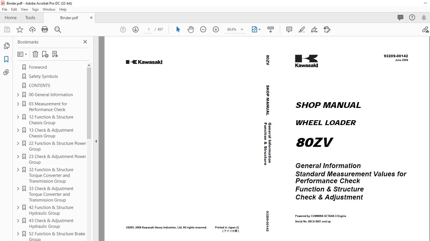
Kawasaki WHEEL LOADER 80ZV Shop MANUAL 93209-00142 – PDF DOWNLOAD
$28.95
Kawasaki WHEEL LOADER 80ZV Shop MANUAL 93209-00142 – PDF DOWNLOAD
General Information
Standard Measurement Values for
Performance Check
Function & Structure
Check & Adjustment
Powered by CUMMINS 6CTAA8.3 Engine
Serial No. 80C4-5001 and up
Description
Kawasaki WHEEL LOADER 80ZV Shop MANUAL 93209-00142 – PDF DOWNLOAD
FILE DETAILS:
Kawasaki WHEEL LOADER 80ZV Shop MANUAL 93209-00142 – PDF DOWNLOAD
Language :English
Pages :457
Downloadable : Yes
File Type : PDF
IMAGES PREVIEW OF THE MANUAL:
DESCRIPTION:
Kawasaki WHEEL LOADER 80ZV Shop MANUAL 93209-00142 – PDF DOWNLOAD
General Information
Standard Measurement Values for
Performance Check
Function & Structure
Check & Adjustment
Powered by CUMMINS 6CTAA8.3 Engine
Serial No. 80C4-5001 and up
Foreword
-
To ensure good machine performance, reduce failures or problems, and prolong the service life of
each component, it is necessary to operate the machine as is directed in the Operator and
Maintenance Manual. - To effectively diagnose and repair the machine, it is important to follow the guidelines laid out
in this Shop Manual.
For the engine, refer to the engine Shop Manual provided by the engine manufacturer.
- The purpose of this manual is to provide information on the product and the correct maintenance and
repair meth- ods. Please read this manual to ensure correct troubleshooting and good repair
service. - This manual will be periodically reviewed and revised for more satisfactory content. If
you have any opinion or requests, please inform us.
TABLE OF CONTENTS:
Kawasaki WHEEL LOADER 80ZV Shop MANUAL 93209-00142 – PDF DOWNLOAD
General Information
Standard Measurement Values for
Performance Check
Function & Structure
Check & Adjustment
Powered by CUMMINS 6CTAA8.3 Engine
Serial No. 80C4-5001 and up
Foreword 4
Safety Symbols 5
CONTENTS 6
00 General Information 18
How to Use Manual 19
Outline 21
Layout of main components 21
Inspection and maintenance table 22
Recommended lubricants 25
Coolant 26
Lubrication chart 27
Weight of main components 28
Bolt tightening torque 29
Hose band tightening torque 33
Liquid gasket and screw lock agent 34
Cautions regarding welding repair service 36
Hydraulic Pressure Test Kit 38
03 Measurement for Performance Check 40
Cautions on Safety 41
Standard Measurement Values for Performance Check 42
12 Function & Structure Chassis Group 44
Front Chassis 45
Rear Chassis 48
Center Pin 51
13 Check & Adjustment Chassis Group 54
Linkage Pin 55
Center Pin 57
22 Function & Structure Power Group 60
Power Line 61
Engine / Transmission 62
Radiator 63
Propeller Shaft 65
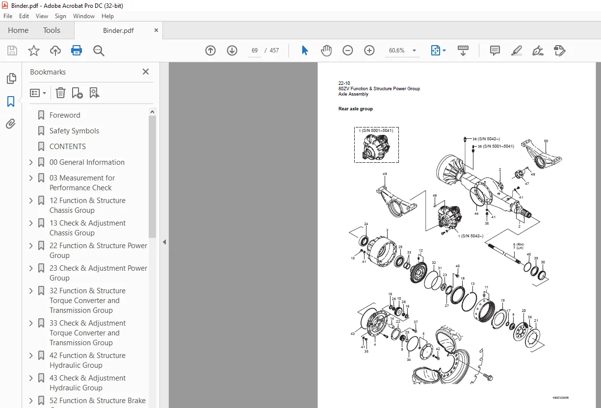
Axle Assembly 68
Axle Support 71
Differential Gear 77
Limited Slip Differential (option) 83
23 Check & Adjustment Power Group 86
Engine 87
Propeller Shaft 88
Axle 90
32 Function & Structure Torque Converter and Transmission Group 96
Torque Converter 97
Torque Converter Gear Pump 98
Transmission 99
Clutch Pack 102
Power Flow Path in the Transmission 106
Hydraulic System Diagram 109
Hydraulic Circuit Diagram 110
Oil Flow 111
T/C and T/M Oil Circulation 112
Control Valve 113
Modulation Mechanism 115
Clutch Solenoid Valve 121
33 Check & Adjustment Torque Converter and Transmission Group 126
Clutch Oil Pressure 127
42 Function & Structure Hydraulic Group 128
Flushing Hydraulic Circuit 129
Cautions on Hydraulic Parts Replacement 130
Hydraulic Circuit Symbols 131
Hydraulic System Operation 135
Layout of Hydraulic Units 137
Hydraulic Tank 138
Hydraulic Pump 145
Hydraulic Cylinder 148
Loading System 151
Reducing Valve (for Pilot Pressure) 152
Pilot valve (S/N 80C4-5001~5270) 153
Pilot valve (S/N 80C4-5271~) 158
Multiple Control Valve (KML28/2T102) 163
Adapter (Orifice) 175
Ride Control (OPT) 176
Steering System 182
Orbitrol® 183
Steering Valve (KVS25-A3 0/A4 0/20) 190
Stop Valve 201
Reducing Valve (for Orbitrol®) 204
Steering Line Filter 205
Fan Motor System 206
Fan Motor Line 207
Reversing Fan Motor System (OPT) 214
43 Check & Adjustment Hydraulic Group 228
Loading/Steering Circuit Relief Valve 229
Hydraulic Cylinder 239
Stop Valve 241
Fan Revolution 242
52 Function & Structure Brake Group 244
Brake System Outline 245
Brake Units Layout 246
Unloader Valve 247
Valve Unit 249
Brake Accumulator Line 250
Brake Valve 254
Service Brake 261
Parking Brake 265
Parking Brake Manual Release 268
Parking Brake Spring Chamber 270
Brake Circuit Check Valve 271
53 Check & Adjustment Brake Group 272
Brake Circuit Oil Pressure 273
Service Brake 277
Parking Brake 280
62 Function & Structure Electrical Group 284
How to Use Electrical Wiring Diagram 285
Electrical Cable Color Codes 286
Electrical Circuit Symbols 287
Sensor Mount 288
Fuse 289
Engine Start Circuit 293
Power Generating / Charging Circuit 303
Transmission Control Circuit and Monitor Circuit 304
Instrument Panel and Switch 321
Electrical Detent Circuit 325
Diode 328
Diagnostic System 332
63 Check & Adjustment Electrical Group 342
Cautions Regarding Electric Circuit Check 343
Electrical Transmission Control System Troubleshooting Flowchart 346
Transmission Controller Abnormal Operation Judgment 347
Electrical Circuit Check 351
72 Function & Structure Air Conditioner Group 370
Air Conditioner 371
Electrical Connections 381
Maintenance 392
A/C Charging 398
Troubleshooting 403
INDEX 416
Maintenance Log 421
Notes 425
Axle Assembly 430
Torque Converter and Transmission 431
Loading/Steering Hydraulic Circuit 432
Brake Circuit 433
Electrical Wiring Diagram 434
(S/N 5001~5050) (1/2) 434
(S/N 5001~5050) (2/2) 435
(S/N 5051~5171) (1/2) 436
(S/N 5051~5171) (2/2) 437
(S/N 5172~) (1/2) 438
(S/N 5172~) (2/2) 439
Electrical wiring diagram abbreviation chart 440
Electrical Wiring Diagram (Reversing Fan Motor Line (OPT)) 441
Electrical Wiring Diagram (CAB) 442
Electrical Connection Diagram 444
(S/N 5001~5136) 444
(S/N 5137~) 445
Electrical Connections (Air Conditioner) (S/N 5001~5305) 446
Electrical Equipment Layout 447
Front chassis 447
Rear chassis (S/N 5001~5050) 449
Rear chassis (S/N 5051~) 450
Floor board 455
S.M 5/2/2025