Kawasaki Wheel Loader 90Z6 Service manual + Parts manual + Wiring diagrams + Troubleshooting manual – PDF DOWNLOAD
Original price was: $96.95.$39.95Current price is: $39.95.
Kawasaki Wheel Loader 90Z6 Service manual + Parts manual + Wiring diagrams + Troubleshooting manual
Description
Kawasaki Wheel Loader 90Z6 Service manual + Parts manual + Wiring diagrams + Troubleshooting manual
File Details:
Kawasaki Wheel Loader 90Z6 Service manual + Parts manual + Wiring diagrams + Troubleshooting manual
Language : English
Pages : 800+
Size : 257 MB
Downloadable : Yes
Format : PDF
KAWASAKI WHEEL LOADER 90Z6 SERVICE MANUAL + PARTS MANUAL + WIRING DIAGRAMS + TROUBLESHOOTING MANUAL – PDF DOWNLOAD:
Image Preview:
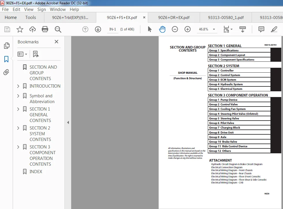
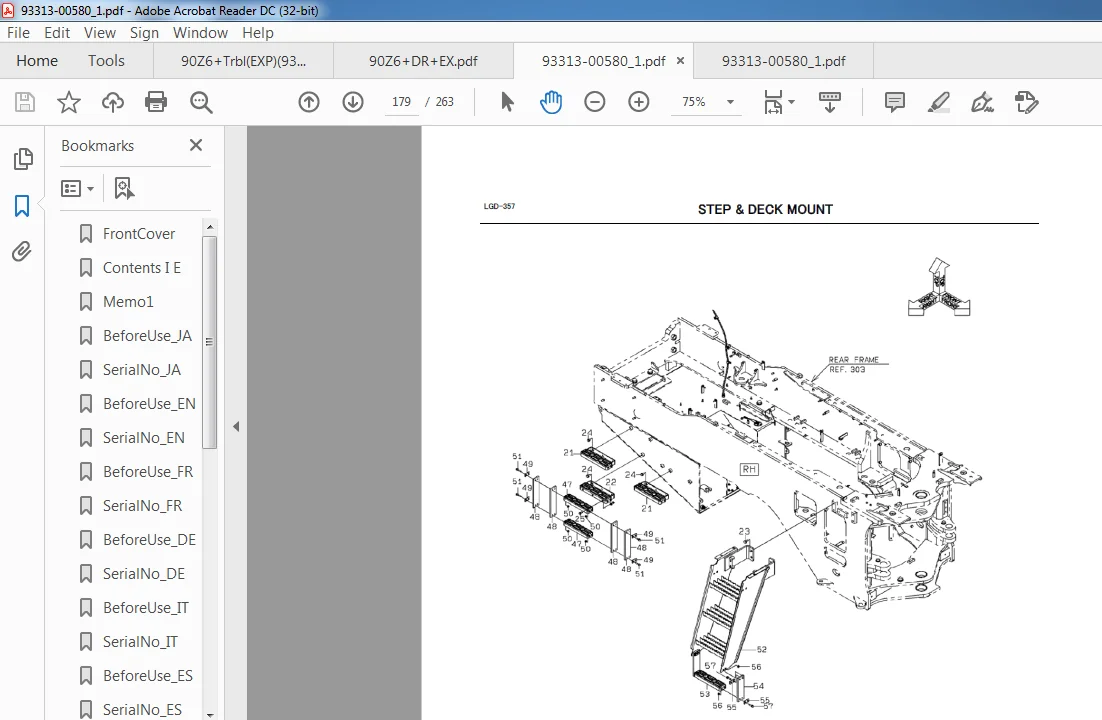
Table of Contents:
Kawasaki Wheel Loader 90Z6 Service manual + Parts manual + Wiring diagrams + Troubleshooting manual
SECTION 1 GENERAL............................................................................  5
	1 Precautions for Disassembling and Assembling...........................................  7
		Precautions for Disassembling and Assembling.........................................  7
			Precautions for Using Floating Seal..............................................  8
			Precautions for Using Nylon Sling................................................  9
	2 Tightening............................................................................. 13
		Tightening Bolts and Nuts............................................................ 13
			Specified Tightening Torque Chart................................................ 13
			Tightening Order................................................................. 14
			Precautions for Split Flange..................................................... 15
			Nut and Bolt Locking............................................................. 15
		Piping Joint......................................................................... 16
			Union Joint...................................................................... 16
			Pipe Joint....................................................................... 17
			O-Ring Seal Joint................................................................ 17
			Quick Coupling................................................................... 18
			Screw-In Connection.............................................................. 19
			 Seal Tape Application........................................................... 19
			Low-Pressure-Hose Clamp Tightening............................................... 19
			Connecting Hose.................................................................. 20
	3 Painting............................................................................... 21
		Painting............................................................................. 21
	4 Bleeding Air .......................................................................... 27
		Bleeding Air from Hydraulic Oil Tank................................................. 27
		Bleeding Air from Hydraulic System................................................... 28
		Bleed Air from the Fuel System....................................................... 29
		Bleeding Air from Radiator........................................................... 30
		Bleeding Air from Brake (Axle)....................................................... 31
	5 Pressure Release Procedure............................................................. 33
		Front Attachment Hydraulic Circuit Pressure Release Procedure........................ 33
		Ride Control Accumulator Pressure Release Procedure.................................. 34
		Parking Brake Accumulator Pressure Release Procedure................................. 35
	6 Preparation............................................................................ 37
		Preparation before Inspection and Maintenance........................................ 37
			Articulation Lock................................................................ 38
			Machine Position for Inspection and Maintenance (lift arm raise)................. 39
SECTION 2 MAINTENANCE STANDARD............................................................... 41
	1 Body................................................................................... 43
		Center Hinge......................................................................... 43
	Pilot Valve (Two Lever Type )............................................................ 45
	2 Front Attachment....................................................................... 47
		Pin and Bushing...................................................................... 47
		Standard Dimensions for Lift Arm and Bucket.......................................... 49
		Bucket Stopper Clearance............................................................. 50
			Bucket Dump Stopper.............................................................. 50
			Bucket Rollback (Tilt) Stopper .................................................. 50
SECTION 3 BODY TOC........................................................................... 51
	1 Cab.................................................................................... 53
		Removal and Installation of Cab...................................................... 53
	2 Counterweight.......................................................................... 69
		Removal and Installation of Counterweight............................................ 69
	3 Center Hinge........................................................................... 71
		Removal and Installation of Center Hinge............................................. 71
		Removal and Installation of the Hydraulic Hoses of Front Chassis Side................ 79
	4 Engine................................................................................. 87
		Removal and Installation of Engine................................................... 87
		Removal and Installation of Exterior Parts...........................................105
			Removal of Side Cover............................................................106
			Installation of Side Cover.......................................................108
			Removal of Engine Roof ..........................................................110
			Installation of Engine Roof......................................................112
			Removal and Installation of Deck and Step/Covers.................................114
		Removal and Installation of Air Cleaner..............................................117
	5 Radiator Assembly......................................................................121
		Replacement of Radiator, Oil Cooler, Air Cooler, and Torque Converter Cooler.........121
	6 Hydraulic Oil Tank.....................................................................139
		Removal and Installation of Hydraulic Oil Tank.......................................139
	7 Fuel Tank..............................................................................147
		Removal and Installation of Fuel Tank................................................147
	8 Pump Device............................................................................153
		Removal and Installation of Pump Device..............................................153
		Disassembly and Assembly of Pump Device..............................................159
			Removal of Pilot Pump and Regulator..............................................160
			Installation of Pilot Pump and Regulator.........................................161
		Disassembly of Main Pump.............................................................163
		Assembly of Main Pump................................................................166
		Disassembly and Assembly of Regulator................................................171
		Removal and Installation of Accessory Pump...........................................179
		Disassembly and Assembly of Accessory Pump...........................................180
	9 Control Valve..........................................................................181
		Removal and Installation of Control Valve............................................181
		Disassembly of Control Valve.........................................................187
		Assembly of Control Valve............................................................191
	10 Pilot Valve...........................................................................195
		Removal and Installation of Pilot Valve (Two Lever Type )  ..........................195
		Disassembly of Pilot Valve (Two Lever Type)..........................................201
		Assembly of Pilot Valve (Two Lever Type).............................................208
		Removal and Installation of Pilot Valve (Multi-Function Joystick Type)...............215
		Disassembly and Assembly of Pilot Valve (Multi-Function Joystick Type)...............221
	11 Charging Block........................................................................227
		Removal and Installation of Charging Block...........................................227
		Disassembly and Assembly of Charging Block...........................................235
	12 Cooling Fan System....................................................................243
		Removal and Installation of Fan Motor................................................243
		Structure of Fan Motor...............................................................249
		Removal and Installation of Fan Pump.................................................251
		Disassembly of Fan Pump..............................................................255
		Assembly of Fan Pump.................................................................258
		Structure of Fan Pump................................................................261
		Removal and Installation of Fan Control Valve (Option)...............................263
		Structure of Fan Control Valve (Option)..............................................265
		Removal and Installation of Reversing Fan Motor (Option).............................267
	13 Exhaust Muffler.......................................................................275
		Removal and Installation of Muffler..................................................275
	14 Ride Control Device...................................................................283
		Removal and Installation of Ride Control Valve and Accumulator (Option)..............283
		Disassembly of Ride Control Valve (Option)...........................................289
		Assembly of Ride Control Valve (Option)..............................................292
	15 Battery Disconnect Switch ............................................................297
		Removal and Installation of Battery Disconnect Switch (Option).......................297
SECTION 4 TRAVEL SYSTEM......................................................................299
	1 Tire...................................................................................301
		Removal and Installation of Front Tire...............................................301
		Removal and Installation of Rear Tire................................................303
	2 Drive Unit.............................................................................309
		Removal and Installation of Drive Unit...............................................309
		Structure of Drive Unit..............................................................321
		Disassembly and Assembly of Drive Unit...............................................329
			Draining Oil and Removing Charging Pump..........................................329
			Removing Control Valve...........................................................331
			Removing Speed Sensor............................................................332
			Installing Charging Pump.........................................................333
			Installing Control Valve.........................................................335
			Installing Speed Sensor..........................................................336
	3 Axle...................................................................................337
		Removal and Installation of Front Axle...............................................337
		Removal and Installation of Rear Axle................................................347
		Disassembly of Axle..................................................................360
			Front Axle Assembly..............................................................355
			Rear Axle Assembly...............................................................355
			Axle Assembly....................................................................356
			Planetary Carrier Assembly ......................................................357
		Removal of Axle Support (Rear Axle)..................................................358
		Disassembly of Axle..................................................................360
			Removal of Housings..............................................................360
			Disassembly of Housings..........................................................361
			Disassembly of Planetary Carrier Assembly........................................363
			Removal of Brake.................................................................364
			Removal of Differential Case Assembly............................................365
			Disassembly of Differential Case Assembly........................................366
			Removal of Bearing Cage Assembly.................................................367
		Assembly of Axle.....................................................................368
			Assembly of Differential Case ...................................................372
			Assembly of Bearing Cage Assembly................................................372
			Installation of Bearing Cage Assembly............................................377
			Installation of Differential Case................................................373
			Adjustment of Ring Gear Backlash and Adjustment of Ring Gear Teeth Engagement....374
			Installation of Bearing Cage Assembly............................................377
			Adjustment of Brake Disc Clearance ..............................................378
			Installation of Brake ...........................................................380
			Assembly of Housings ............................................................382
			Preload Adjustment of Axle Shaft Bearing (Shim Adjustment) ......................384
			Assembly and Installation of Planetary Carrier Assembly..........................386
			Installation of Housing..........................................................388
			Installation of Axle Support (Rear Axle).........................................390
		Disassembly of Differential..........................................................393
			Torque Proportional Differential (TPD)...........................................400
			Limited Slip Differential (LSD)..................................................401
			Disassembly of Bearing Cage Assembly.............................................395
			Disassembly of Differential Case Assembly (TPD)..................................397
			Disassembly of Differential Case Assembly (LSD)..................................398
		Assembly of Differential.............................................................400
			Torque Proportional Differential (TPD)...........................................400
			Limited Slip Differential (LSD)..................................................401
			Assembly of Differential Case Assembly (TPD).....................................402
			Assembly of Differential Case (LSD)..............................................404
			Assembly of Bearing Cage ........................................................406
	4 Propeller Shaft........................................................................409
		Removal and Installation of Propeller Shaft..........................................409
			Removal of Bottom Covers (Option)................................................409
			Removal of Second Propeller Shaft................................................410
			Removal of Third Propeller Shaft ................................................413
			Installation of Third Propeller Shaft............................................414
			Installation of Second Propeller Shaft...........................................415
			Installation of Bottom Covers (Option)...........................................418
	5 Brake Valve............................................................................419
		Removal and Installation of Brake Valve..............................................419
		Disassembly of Brake Valve Assembly (Option).........................................423
		Assembly of Brake Valve Assembly (Option)............................................426
		Structure of Brake Valve ............................................................429
		Disassembly of Brake Valve ..........................................................430
		Assembly of Brake Valve .............................................................431
		Brake Valve Maintenance Standard.....................................................432
	6 Steering Pilot Valve...................................................................433
		Removal and Installation of Steering Pilot Valve.....................................433
		Disassembly of Steering Pilot Valve..................................................437
		Assembly of Steering Pilot Valve.....................................................440
	7 Steering Valve.........................................................................445
		Removal and Installation of Steering Valve ..........................................445
		Disassembly and Assembly of Steering Valve...........................................449
	8 Steering Cylinder......................................................................453
		Removal and Installation of Steering Cylinder .......................................453
		Disassembly of Steering Cylinder.....................................................457
		Assembly of Steering Cylinder........................................................460
		Removal and Installation of Steering Accumulator.....................................463
	9 Secondary Steering Device..............................................................465
		Removal and Installation of Secondary Steering Pump (Option).........................465
	10 Stop Valve............................................................................469
		Removal and Installation of Stop Valve...............................................469
		Adjustment of Stop Valve Installation Position.......................................471
		Disassembly of Stop Valve............................................................473
		Assembly of Stop Valve...............................................................474
	11 Axle Oil Cooler.......................................................................475
		Removal and Installation of Axle Oil Cooler (Option).................................475
		Structure of Oil Cooler Assembly (Option)............................................487
		Structure of Oil Cooler Pump Unit (Option)...........................................488
		Structure of Check Valve Assembly (Option)...........................................490
SECTION 5 FRONT ATTACHMENT TOC...............................................................493
	1 Front Attachment.......................................................................495
		Removal and Installation of Front Attachment.........................................495
			Installation Position (Lift Arm).................................................500
			Installation Position (Bucket Cylinder)..........................................501
		Removal and Installation of Lever (Bell Crank))......................................507
			Installation Position (Lever (Bell Crank)).......................................512
			Installation Position (Bucket Link)..............................................513
			Installation Position (Bucket Cylinder)..........................................514
		Removal and Installation of Bucket...................................................521
			Installation Position (Lift Arm).................................................523
			Direction of Install (Bucket Link)...............................................524
	2 Cylinder...............................................................................527
		Removal and Installation of Lift Arm Cylinder .......................................527
			Installation Position (Lift Arm Cylinder)........................................529
			Removal and Installation of Bucket Cylinder......................................533
				Installation Position (Bucket Cylinder)......................................537
			Disassembly of Lift Arm Cylinder.................................................543
			Assembly of Lift Arm Cylinder....................................................548
			Disassembly of Bucket Cylinder...................................................555
			Assembly of Bucket Cylinder......................................................560
INDEX........................................................................................567
Description:
Kawasaki Wheel Loader 90Z6 Service manual + Parts manual + Wiring diagrams + Troubleshooting manual
The service manual covers the following files:
90Z6+DR+EX-Cover.pdf
90Z6+DR+TR.pdf
90Z6+DR+TR-Cover.pdf
90Z6+FS+EX.pdf
90Z6+FS+EX-Cover.pdf
90Z6+FS+TR.pdf
90Z6+FS+TR-Cover.pdf
90Z6+FS+TR-Diagrams.pdf
90Z6+PC+????-Cover.pdf
90Z6+PC+????-Cover.pdf
90Z6+PC+??-Cover.pdf
90Z6+T+EX-Cover.pdf
90Z6+T+TR.pdf
90Z6+T+TR-Cover.pdf
90Z6+Trbl(EXP)(93213-00771).pdf
93313-00550.pdf
93313-00580_1.pdf
93313-00580_2.pdf
93313-00581-1.pdf
93313-00581-2.pdf
93313-00581???.pdf
93313-00600(TURKEY)..pdf
93313-00610.pdf
15M002+90Z6+OM+Revision.pdf
90Z6_OMM(TR)(93113-00762).pdf
90Z6_TT(93213-00801)TR (1).pdf
90Z6_TT(93213-00801)TR.pdf
90Z6+(F&S)-Diagrams(00761).pdf
90Z6+DR+EX.pdf
- Our shop manuals consist of the Technical Manual, the Workshop Manual and the Engine Manual.
Information included in the Technical Manual: Technical information needed for machine pre-delivery and delivery, operation and activation of all devices and systems, operational performance tests, and troubleshooting procedures. Each page has a number, located on the center lower part of the page, and each number contains the following information: Example: Technical Manual: T 1-3-5 T Technical Manual 1 Section Number 3 Group Number 5 Consecutive Page Number for Each Group - Information included in the Workshop Manual: Technical information needed for maintenance and repair of the machine, tools and devices needed for maintenance and repair, maintenance standards, and removal / installation and assembly / disassembly procedures. Information included in the Engine Manual: Technical information needed for machine pre-delivery and delivery and maintenance and repair of the machine, operation and activation of all devices and systems, troubleshooting and assembly / disassembly procedures
Please Note:
- This is the SAME exact manual used by your dealers to fix your vehicle.
- The same can be yours in the next 2-3 mins as you will be directed to the download page immediately after paying for the manual.
- Any queries / doubts regarding your purchase, please feel free to contact [email protected]