
KMC K7 1.5T GDI Engine Electronic Control Workshop Manual – PDF
Original price was: $29.95.$17.95Current price is: $17.95.
Chapter 4 engine electronic control workshop manual for the KMC K7 1.5T GDI, covering the Delphi MT92.1 ECM, every sensor and actuator circuit, component test values and the full fault code diagnosis tables.
Description
KMC K7 1.5T GDI Engine Electronic Control Workshop Manual
The KMC K7 1.5T GDI Engine Electronic Control Workshop Manual is the engine management volume of the K7 workshop set. It deals exclusively with the electronic control side of the 1.5 T GDI engine: the Delphi MT92.1 control module, the sensors and actuators wired to it, the harness circuits between them, and the diagnostic routines and fault codes that lead a technician to the failed part. Everything is written from the workshop floor outward, so circuit tests, terminal numbers, tightening torques and resistance values sit alongside the theory rather than in a separate chapter.
File Details
- Manual type: Engine electronic control workshop manual (Chapter 4)
- Vehicle: KMC K7
- Engine: 1.5T GDI (1.5TGDI), four-cylinder gasoline direct injection
- Engine control module: Delphi MT92.1
- Language: English
- Page count: 124 pages
- File format: PDF
Chapters Covered
- 4.1 Attentions – common maintenance precautions, common diagnostic tools, engine OBD system cautions
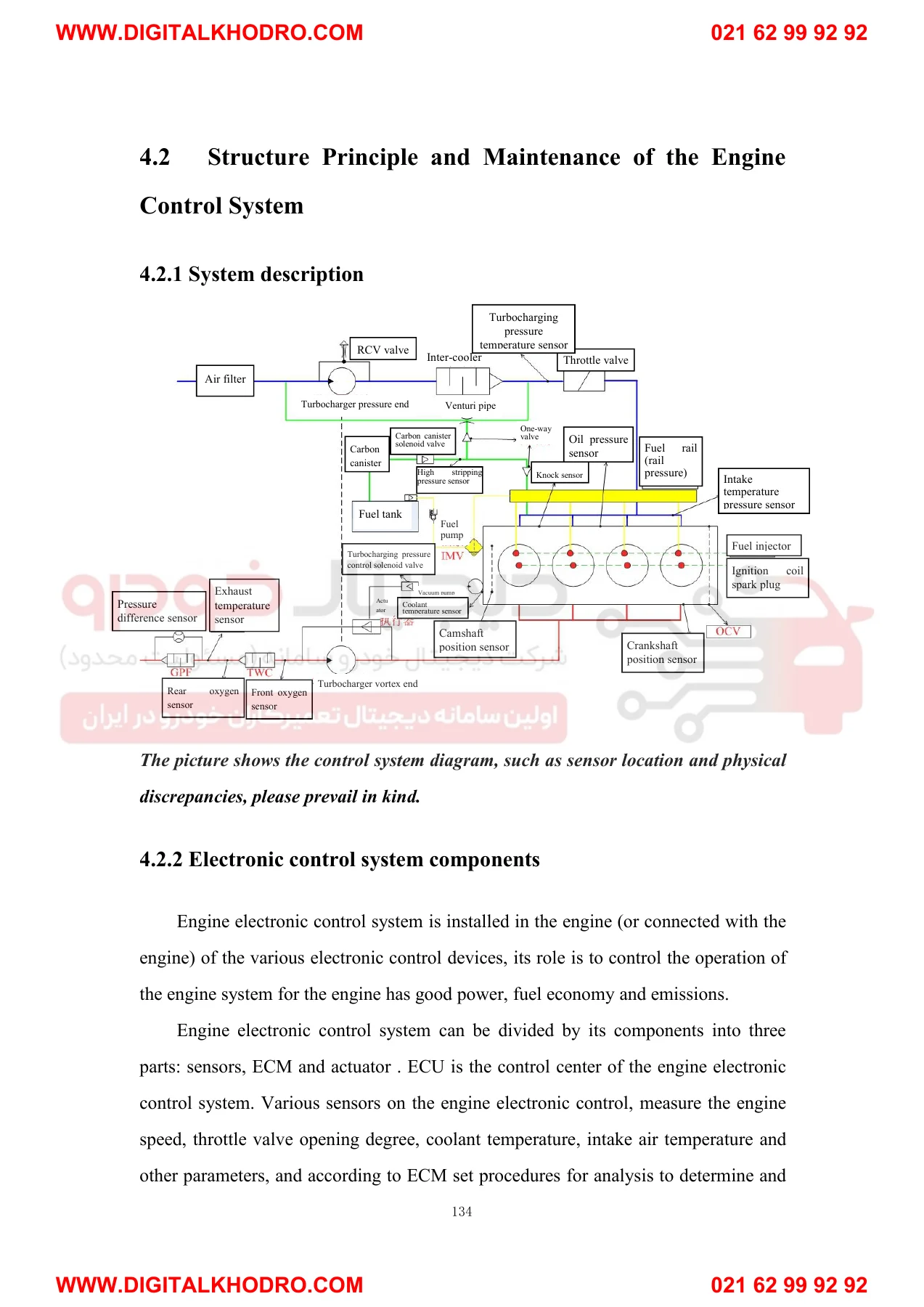
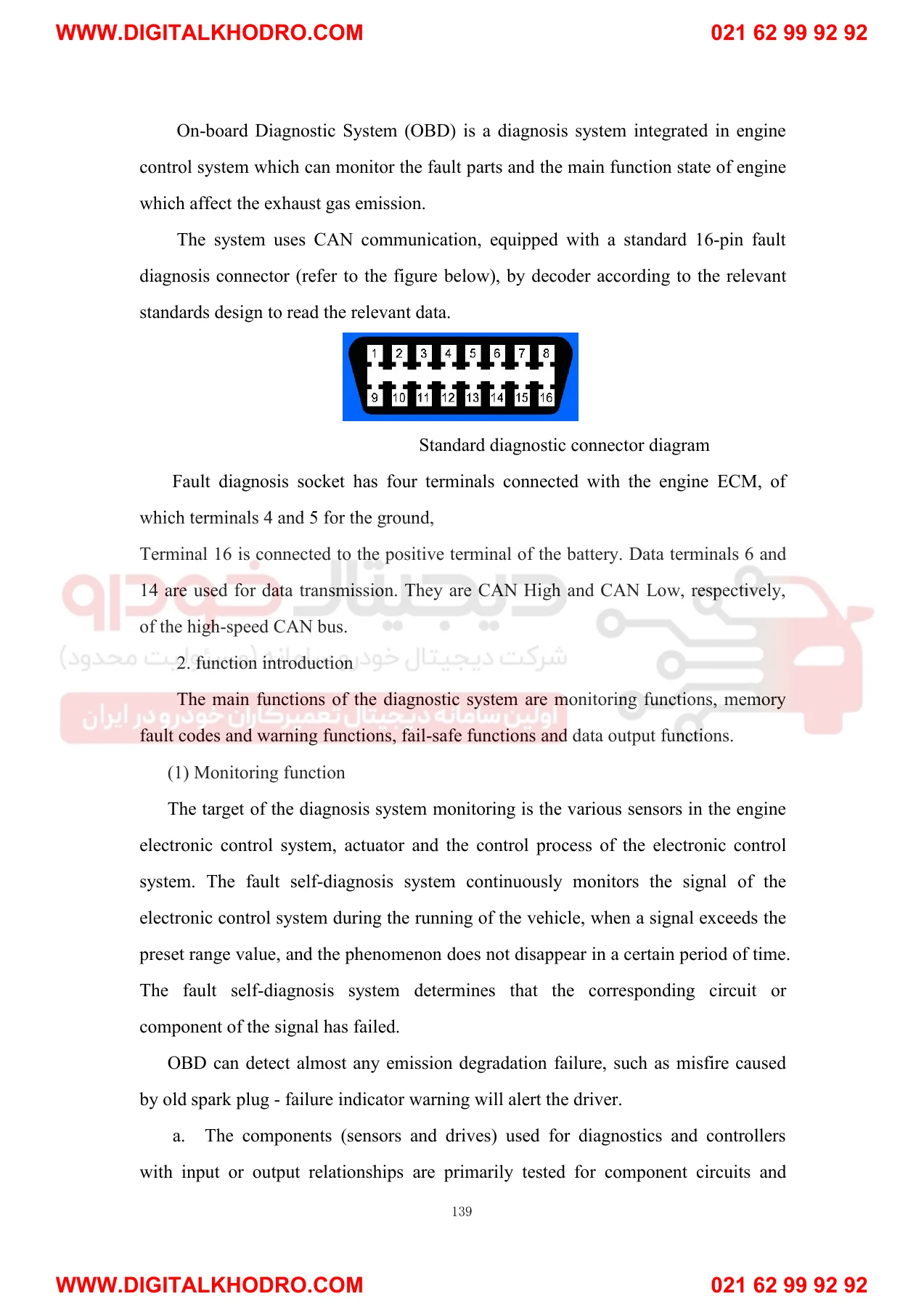
- 4.2 Structure Principle and Maintenance of the Engine Control System – system description, electronic control system components, fuel injection control system, ignition control system, air intake control system, emission control system, electronic water pump control, crankcase ventilation control system, vehicle diagnostic system
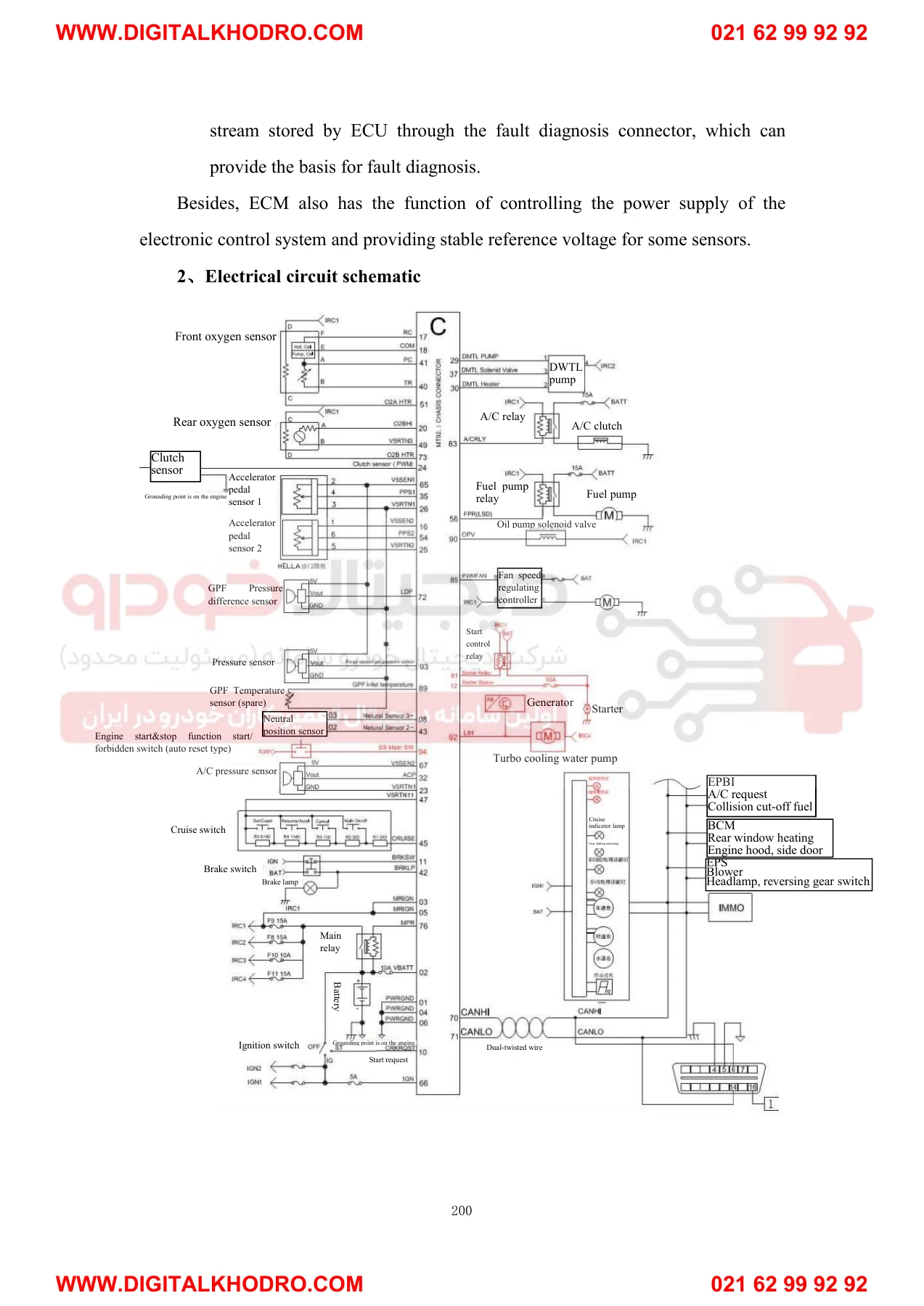
- 4.3 Structure Principle and Maintenance of the Engine Electric Components – temperature pressure sensor, coolant temperature sensor, electronic throttle valve, crankshaft position sensor, camshaft position sensor, front oxygen sensor, rear oxygen sensor, fuel injector, knock sensor, OCV valve, carbon canister solenoid valve, ignition coil, spark plug, high pressure fuel pump, variable displacement oil pump, ECM
- 4.4 Engine Control System Fault Diagnosis Process – electronic control system common failure and main causes, common fault diagnosis, fault code analysis by code
Read end to end, this K7 1.5T GDI engine electronic control workshop manual gives a technician three things that rarely arrive together in one file: the control strategy behind each system, the physical test procedure for every component in that system, and the fault code table that ties a stored code back to a specific circuit. Chapter 4.2 explains how the MT92.1 ECM calculates injection quantity, ignition angle and closing angle, how the electronic throttle and variable valve timing are driven, and how the emission, crankcase ventilation and electronic coolant pump controls interact. Chapter 4.3 then takes each component in turn and gives the connector pinout, the supply voltage it should see, the resistance or output signal it should produce, the tightening torque for its fastener, and the symptoms a failed unit produces on the road.
Fault Code Diagnosis by Code
Chapter 4.4 is where the manual earns its place on the bench. It opens with the common failure patterns of the electronic control system itself – ECM faults, sensor faults, actuator faults and control circuit faults – and explains how each one shows up in the data stream. From there it works through the classic no-start, hard-start, unstable idle, high idle, fluctuating idle, stalling and lack-of-power complaints with step-by-step check sequences, then moves into fault code analysis with the circuit diagram, the possible causes and the repair action for each group of codes.
The code groups covered include inlet and exhaust VCP faults with the OCV valve and camshaft sensor circuits (P0011, P0012, P0014, P0015, P0016, P0017, P0026, P0027, P0076, P0077, P0079, P0080, P0340, P0341, P0366); oxygen sensor heater circuits (P0031, P0032, P0037, P0038); electronic throttle valve airflow, position sensor and reference voltage faults (P0068, P0122, P0123, P0222, P0223, P0641, P0651, P2119, P2135); temperature and pressure sensor circuits (P0072, P0073, P0107, P0108, P0112, P0113, P0117, P0118, P0237, P0238, P0234, P0299); oxygen sensor signal faults (P0131, P0132, P0133, P0134, P0137, P0138, P0140); fuel system too rich or too lean (P0171, P0172, P1167, P1171, P2187, P2188); fuel pump relay (P0230); injector circuits (P0261, P0262, P0264, P0265, P0267, P0268, P0270, P0271, P2147 through P2150); misfire (P0300); knock sensor (P0324, P0325); crankshaft position sensor (P0335, P0336, P1336); ignition coil (P0351 through P0354); catalytic converter efficiency (P0420); carbon canister solenoid valve (P0458, P0459); fan control (P0480, P0481); idle speed (P0506, P0507); system voltage (P0562, P0563); ECU processor (P0601, P0602, P0606, P060A, P1516, P2101); electronic accelerator pedal (P2122, P2123, P2127, P2128, P2138); and engine power management (P2104, P2105, P2106, P2110).
Component Service Data Inside
The component chapters carry the numbers a technician actually needs at the vehicle. Intake temperature and pressure sensors, coolant temperature sensor, electronic throttle valve, crankshaft and camshaft position sensors, front and rear oxygen sensors, fuel injectors, knock sensor, OCV valve, carbon canister solenoid valve, ignition coil and spark plug each get their own section with pin definitions, reference voltages, heater and coil resistances, working gaps and bolt torques. The high pressure fuel pump and variable displacement oil pump sections add safety valve opening pressures, flow figures and end surface clearance limits, and the ECM section closes the chapter with connector layouts and the electrical circuit schematic.
What This Manual Lets You Do
With the KMC K7 1.5T GDI Engine Electronic Control Workshop Manual open, you can read and clear fault codes, follow a code to the exact circuit it belongs to, and confirm the fault with a digital multimeter or oscilloscope before a single part is ordered. You can test a throttle valve position sensor against its 5 V reference and 0-5 V signal range, check an injector coil at about 1.3 ohms, verify an oxygen sensor heater at its rated resistance, measure the crankshaft sensor working gap, and self-learn the throttle valve and gear signal afterwards so the repair actually holds. You can also diagnose the driveability complaints that never set a code – unstable idle, hesitation, poor power – by working through the symptom-based check sequences in 4.4.
Why It Matters
Engine management faults on a GDI engine are rarely solved by swapping parts. A throttle body fitted without self-learning, a harness connector probed with the wrong meter, or an ECM unplugged with the ignition still on can all turn a small fault into an expensive one. This manual sets out the precautions, the correct test method, the standard value and the installation torque for each component, so the diagnosis is confirmed rather than guessed. The safety warnings on high pressure fuel lines, ignition system spark testing and three-way catalytic converter protection are included because the cost of ignoring them is measured in components, not minutes.
IMAGES PREVIEW
Instant PDF Delivery
The file is delivered as a downloadable PDF immediately after payment – no shipping, no waiting, no regional restrictions. Open it on a laptop, tablet or phone in the workshop, print the pages you need for the bay, and search or scroll straight to the system you are working on. Whether you are tracing one fault code on a K7 1.5T GDI or working through the whole electronic control system, the information is in your hands the moment you check out.



Reviews
There are no reviews yet.