
Kobelco SK210LC-8 Acera Mark 8 Excavator Parts Catalog Tier III (NA) PDF Download
Original price was: $39.95.$24.95Current price is: $24.95.
Complete Kobelco SK210LC-8 Acera Mark 8 Tier III (NA) excavator parts catalog in PDF, with exploded diagrams, part numbers, and descriptions covering engine, hydraulics, superstructure, undercarriage, and attachments.
Description
Kobelco SK210LC-8 Acera Mark 8 Parts Catalog – Tier III (NA)
This is the full Kobelco SK210LC-8 Acera Mark 8 excavator parts catalog for Tier III (NA) machines built from 12/06 onward. It is organized the way a parts counter and workshop actually use a catalog: exploded illustrations paired with reference numbers, Kobelco part numbers, quantities, and descriptions. Whether you are identifying a single O-ring for a hydraulic line or rebuilding a swing motor, this PDF gives you the exact part references for the machine.
File Details
- Manual type: Parts Catalog
- Brand: Kobelco
- Model: SK210LC-8 Acera Mark 8
- Application: Excavator, Tier III (NA) (12/06-)
- Language: English
- Page count: 675 pages
- File format: PDF
Chapters Covered
The catalog is divided into engine, hydraulic, superstructure, undercarriage, attachments, optional parts, name plates, and tools sections. A representative outline of what is inside:
- Engine
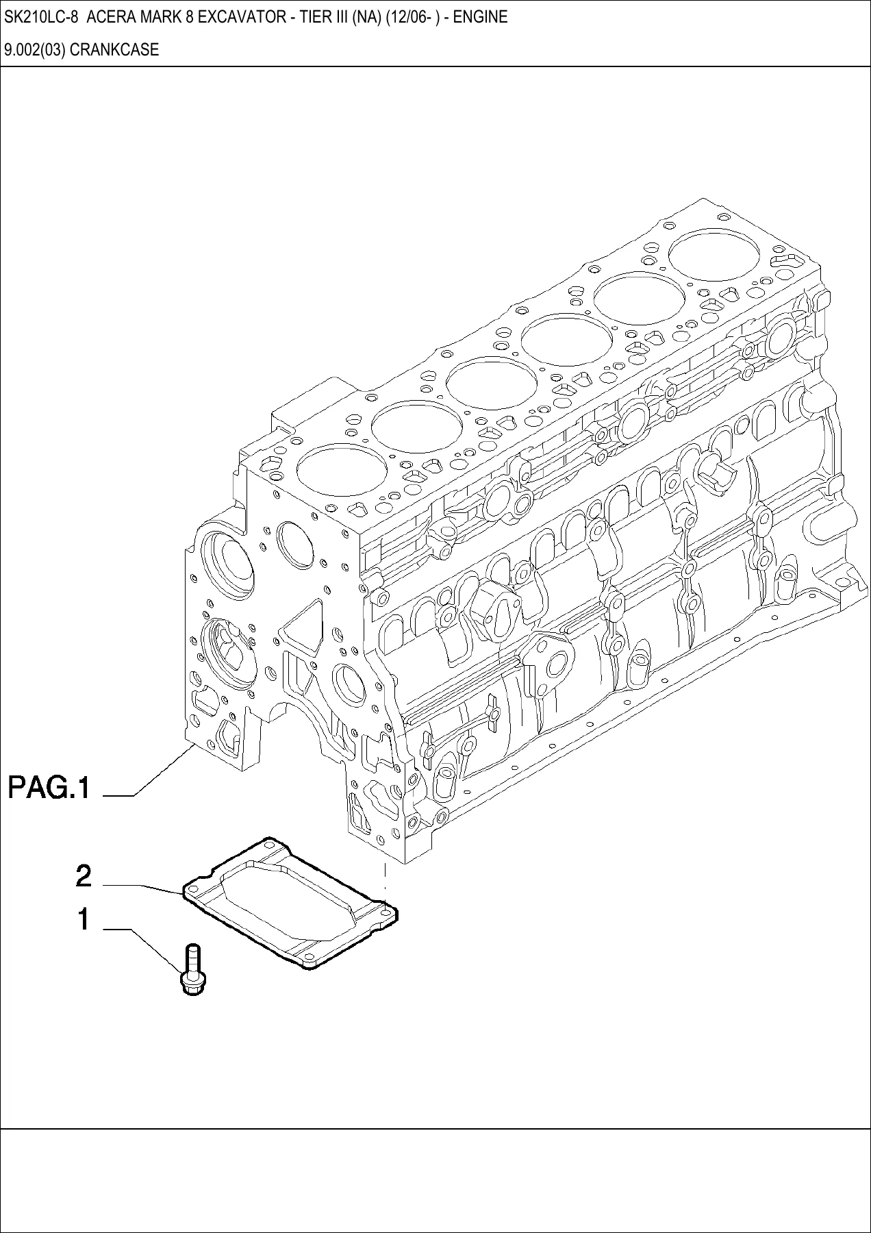
- 9.002 Crankcase (three sub-groups)
- 9.003 Engine Oil Sump
- 9.004 Crankcase Covers (three sub-groups)
- 9.006 Cylinder Head
- 9.007 Cylinder Head Covers
- 9.008 Rocker Shaft
- 9.010 Exhaust Manifold
- Crankshaft, connecting rod, piston and ring assemblies
- Flywheel and damper
- 9.016 Camshaft – Timing Control
- 9.017 Injection Pump and Control
- 9.022 Turbocharger
- 9.023 Engine Oil Dipstick
- 9.025 Oil Filters – Engine
- 9.027 Heat Exchanger – Engine
- 9.029 Piping – Engine Cooling System
- 9.032 Fan Drive
- 9.033 Power Take Off
- 9.034 Starter Motor and Components
- 9.035 Alternator and Components
- Hydraulic Components
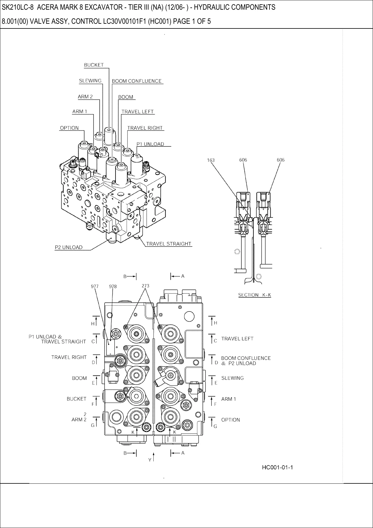
- 8.001 – 8.005 Control Valve Assembly LC30V00101F1 (five-page breakdown)
- 8.006 Port Relief Valve YN22V00002F1
- 8.007 Overload Valve YN22V00029F1
- 8.008 Control Valve YN30V00104F1 (HC100)
- 8.009 Control Valve YN30V00108F1 (HC120)
- 8.010 Swing Motor Assembly YN15V00035F1
- 8.011 Swing Reduction Assembly
- 8.012 Swing-Reactionless Valve
- 8.013 Relief Valve Assembly
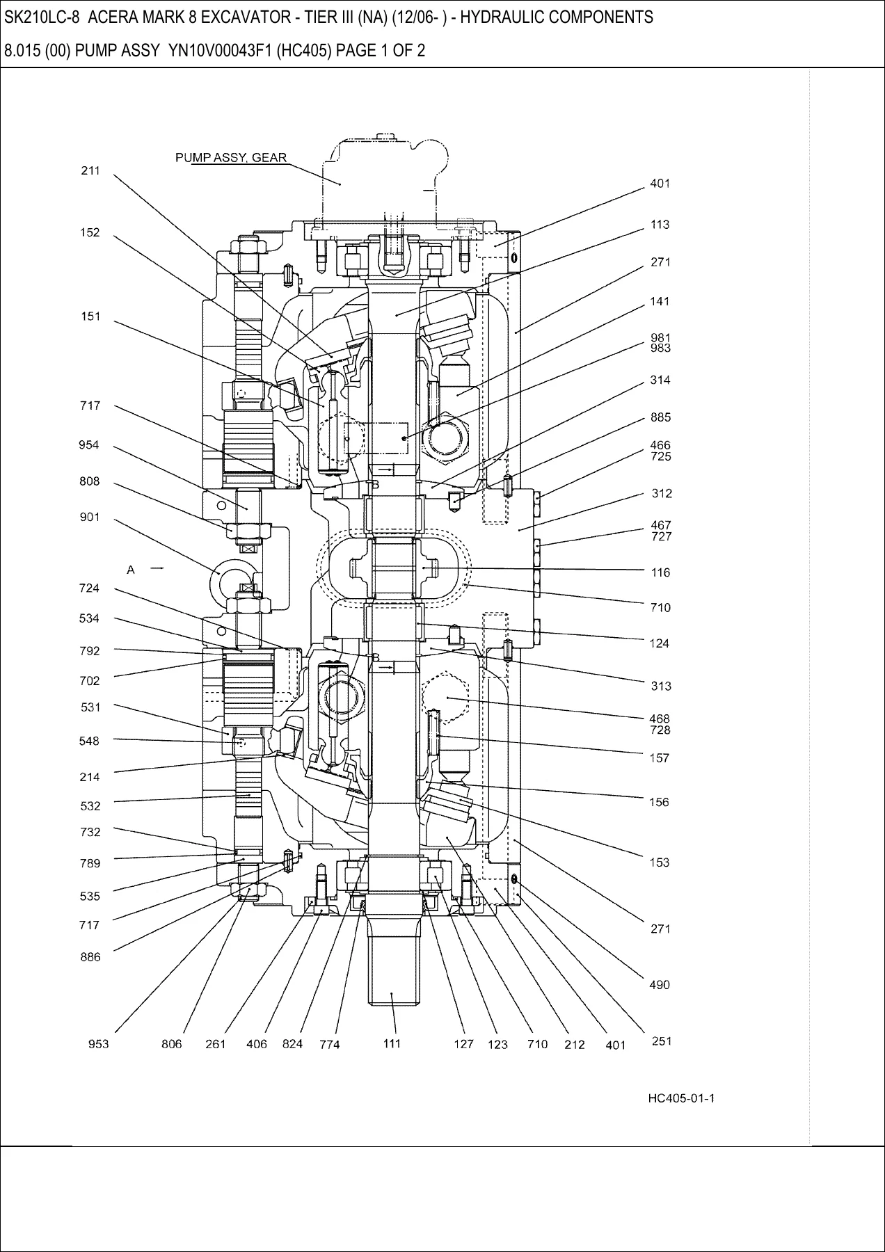
- 8.014 – 8.016 Pump Assembly YN10V00036F1 and YN10V00043F1
- 8.017 – 8.018 Regulator Assembly YN10V01009F1
- 8.019 Gear Pump Assembly
- 8.020 – 8.021 Pump and Gear Case Assembly
- 8.022 Boom Cylinder Assembly
- 8.023 – 8.024 Arm Cylinder Assembly
- 8.025 Bucket Cylinder Assembly
- 8.026 Pilot Valve
- 8.027 – 8.034 Solenoid Valve Assemblies
- 8.035 – 8.036 Selector Valve Assemblies
- 8.037 – 8.038 Holding Valve Assemblies
- 8.039 Swivel Joint Assembly
- 8.040 Pilot Valve (Propelling)
- Superstructure
- 1.000 Upper Frame Assembly and Counterweight Installation
- 1.001 Upper Frame Group (H&W)
- 1.002 – 1.003 Engine Installation
- 1.004 Engine Control Assembly
- 1.005 – 1.007 Radiator Installation, Group, and Assembly
- 1.008 Air Cleaner Assembly
- 1.009 Muffler Assembly
- 1.010 Fuel Lines
- 1.011 Fuel Tank Installation
- 1.012 Hydraulic Tank Assembly
- 1.013 Power Take Off Assembly
- 1.014 Swing Motor Installation
- 1.015 Main Valve Installation
- 1.016 – 1.017 Hydraulic Lines, Pump
- 1.018 – 1.019 Hydraulic Lines, Upper
- 1.020 Hydraulic Lines, Swivel
- 1.021 – 1.022 Hydraulic Lines, Return
- 1.023 – 1.028 Operator Controls and Pedal Assemblies
- 1.029 – 1.037 Control Box, Grip, Radio, Arm Rest, Clamp and Lever Assemblies
- 1.038 Control Lines, Remote
- 1.039 – 1.044 Control Lines, Main, Valve, Pump and Propel
- 1.045 Plate Installation, Floor
- 1.046 – 1.048 Mirror Installations
- 1.049 – 1.053 Cab Installation, Cab Assembly, and Roof Window
- 1.054 Front Window Assembly
- 1.055 – 1.056 Cab Door
- 1.057 – 1.058 Seat and Seat Belt
- 1.059 – 1.064 Guard Installations (Common, Pattern Change, Bonnet, Side Panel, Partition, Under Cover)
- 1.065 – 1.066 Instrument Panel Assembly
- 1.067 Gauge Cluster Assembly
- 1.069 – 1.070 Controller Installation and Relay Box
- 1.071 Battery Assembly
- 1.072 – 1.077 Air Conditioner, Dryer, Compressor Assemblies
- 1.078 Electrical Assembly, Upper
- 1.079 – 1.080 Lamp Mounting
- 1.081 – 1.084 Harness Assemblies
- Undercarriage
- 2.001 Lower Frame
- 2.002 Slewing Ring Assembly
- 2.003 – 2.005 Idler Assemblies
- 2.006 – 2.006(02) Track Roller Assemblies
- 2.007 Upper Roller Assembly
- 2.008 Shoe Assemblies (600mm, 700mm, 800mm, 900mm)
- 2.009 – 2.010 Lower Hydraulic Lines
- 2.011 Under Cover Assembly
- 6.002 Alarm Assembly
- Attachments
- 3.001 – 3.002 Boom Installation 5.65m
- 3.003 Boom Assembly
- 3.004 – 3.005 Hydraulic Lines, Boom
- 3.006 Lamp Mounting – Boom
- 3.007 – 3.009 Arm Installation 2.94m and Arm Assembly
- 3.010 Hydraulic Lines – Arm
- 3.011 Bucket Installation
- 3.012 Long Reach Boom
- 3.013 – 3.014 Gear Case Assemblies
- 3.015 Rotation Valve Installation
- Optional Parts
- Optional Track Roller Assembly
- Nibbler and Breaker Valve and Hydraulic Line Installations
- Rotation Control Lines
- Multi Control Lines
- Safety Control Lines
- Control Lines, Block (Standard, 2-Way, PT-2Pedal)
- Remote Control Lines (Foot and Hand)
- Instrument Panel Assembly (Nibbler and Breaker)
- Boom Hydraulic Lines (Nibbler & Breaker, Rotation)
- Arm Hydraulic Lines (Nibbler & Breaker, Rotation, Long)
- Safety Hydraulic Lines (Boom, Arm)
- Connector Assembly
- Long Reach Arm and Boom Groups
- Hydraulic Lines (Boom, Arm, Bucket) for Long Reach
- Pattern Changer, Upper Harness Assemblies
- Sun Visor Assembly
- Extreme Reach Control Lines and Counterweight Installation
- Long Reach Controller Installation
- Lamp Installations
- Mirror, Alarm, Cap Assemblies
- Slewing Ring and Shoe Assemblies (H&W)
- Step Installations
- Vandalism Guard
- Idler, Roller, Low Frame, Propel Motor Installations (H&W)
- Lamp Mounting and Flasher Lamps
- Long Reach Boom, Arm and Bucket Installations
- Name Plates
- Lubrication Chart
- Boom Name Plate
- Frame Label Locations
- Caution Labels
- Cab Label Locations
- Exterior Decals
- Lift Charts
- Anti-Skid
- Pattern Change Labels
- Long Reach Labels
- Tools and Spare Parts
- Tool and Accessory Kit (including shims, grease gun, grease)
- Element Kit (oil element, fuel elements, pre-filter, operator manual, parts manual, O-rings)
For anyone maintaining, repairing, or restoring an SK210LC-8 Acera Mark 8, this catalog is the reference that turns “I need that part” into a concrete order number. The exploded illustrations show how each assembly goes together, while the reference tables give Kobelco part numbers, quantities per assembly, and short descriptions. That combination is what lets a technician confirm the correct O-ring, gasket, seal kit, bearing, spool, or hardware before a machine goes up on the service deck – and it is equally useful when quoting a repair, checking whether a component is serviced separately, or looking up a serial-number-dependent change.
Engine Groups in Detail
The engine section alone is a full teardown reference. Crankcase pages show the block casting, dowels, plugs, screws, and bushings, plus a separate tappet and lubrication oil jet nozzle listing. Cylinder head pages cover the head assembly, collets, exhaust and inlet valves, valve seals, springs, retainers, valve seats, and the alternative cylinder head gaskets in different thicknesses. Further pages break out the rocker shaft, push rods, rocker arms, and supports. The crankshaft listing includes main bearing sets in standard and oversize options, thrust washers, and the crankshaft gear. Connecting rod pages list bushings, screws, and rod bearing sets. Piston pages show piston-and-ring kits in standard and oversize, piston pins, snap rings, and ring kits. The camshaft section includes the driven gear, flange, and dowel. Injection pump pages list the pump assembly, water temperature sender, wire harness, and the gear/gasket/stud/nut/hose/fitting/seal items for the control side. Turbocharger, dipstick, oil filters, heat exchanger, cooling system piping, fan drive, PTO cover, starter motor and alternator components round out the engine listings.
Hydraulic Components in Detail
The hydraulic section is built around the control valve assembly LC30V00101F1, which is presented across multiple pages with sectional views showing travel left, boom confluence, slewing, arm 1, option, travel right, boom, bucket, arm 2, P1/P2 unload, and travel straight. The reference tables list guards, covers, plates, pistons, O-rings, gaskets, screws, spools, springs, seats, bolts, stops, poppets, plugs, relief valves, and repair kits for the various spool positions. Separate sections cover the port relief valve, overload valve, the HC100 and HC120 control valves, the swing motor assembly, swing reduction, swing-reactionless valve, relief valve, main pump, regulator, gear pump, gear case, and the boom, arm, and bucket cylinders – each with rod-side and piston-side repair kits. Solenoid valve sections (HC851 through HC854, HC860, HC861) list spools, sleeves, springs, rings, seats, O-rings, solenoids, and nuts. Selector and holding valves, plus the swivel joint assembly, complete the hydraulic picture.
Superstructure and Operator Station
The upper frame section covers the frame, insulation, seals, plates, grommets, and mounting hardware, along with the counterweight installation and its shims and hardware. The engine installation pages list the brackets, covers, hoses, connectors, elbows, clamps, thermo switches, fan, pressure switch, adapter, seal, and thermoguard switch. Radiator pages break the assembly down into core, oil cooler, air cooler, insulators, guards, shroud, gaskets, hoses, collars, rubber mounts, and hardware. The air cleaner and muffler assemblies follow. Fuel lines, fuel tank, and hydraulic tank assemblies list hoses, connectors, quick disconnects, packings, bolts, clips, sensors, strainer, breather, element, check valve, spring, filters, gauge, and O-rings. Operator control sections cover the control box, grips, arm rest, propel levers, pedal assemblies, and the instrument panel with its gauge cluster, potentiometer, ignition switch, lighter, hour meter, ducts, speakers, and guards. The cab, door, front window, roof window, seat, and seat belt assemblies are fully broken out. The electrical section lists the relay box, fuses, relays, battery installation, harness assemblies for upper, cab, and floor plate, and lamp mountings.
Undercarriage and Attachments
The lower frame, slewing ring, idler, track roller, upper roller, and shoe assemblies are all presented with their component parts. Track roller assembly listings include the roller, collars, shaft, bushing, pin, floating seal, O-rings, and plugs, along with the bolt/nut sets for the shoes. The shoe assembly pages list track links, bushings, pins, collars, seals, and the shoe plates themselves. The lower hydraulic lines section covers tubes, hoses, connections, clamps, screws, washers, and O-rings. Attachment sections cover the 5.65m boom installation, boom assembly, boom hydraulic lines, lamp mounting, 2.94m arm installation, arm assembly, arm hydraulic lines, bucket installation, and the long reach boom and arm groups. Each cylinder installation page lists the pins, screws, nuts, shims, and seals needed for the pivot points.
Optional Equipment Coverage
The optional parts section is substantial. It includes the nibbler and breaker valve installation, hydraulic lines for nibbler and breaker on the upper structure, boom, and arm (in 2.94m and 3.5m lengths), rotation control lines, multi control lines, safety control lines, block control lines in standard, 2-way, and PT-2pedal configurations, remote control lines for foot and hand operation, and the corresponding instrument panel assembly. There are also optional long-reach boom, arm, bucket, and cylinder installation sections, a controller installation for long reach, and lamp installations. The optional undercarriage parts include H&W slewing ring, shoe, idler, roller, low frame, and propel motor installations. The vandalism guard and step installations are also listed.
Name Plates and Labels
The name plate section covers lubrication charts, boom name plates, frame label locations, caution labels, cab label locations, exterior decals, lift charts for 600mm, 700mm, 800mm, and 900mm shoes, anti-skid sheets, pattern change labels, and long reach labels. These are the decals and plates that keep safety information, lifting capacity data, and lubrication guidance visible on the machine.
Tools and Spare Parts
The final section lists the tool and accessory kit, including the grease gun, grease, and a full range of shims for the boom, arm, and bucket pivot points. The element kit lists the oil element, fuel elements, fuel pre-filter element, operator manual, parts manual, and O-rings.
Why This Kobelco SK210LC-8 Acera Mark 8 Parts Catalog Matters
Ordering the wrong part costs time and money. This catalog removes that risk by tying every component to an exploded view and a Kobelco part number, so you can confirm what you need before you call the dealer or place an online order. It is the difference between guessing at a seal kit and knowing the exact repair kit number for a boom cylinder, swing motor, or control valve spool. It also helps when a machine has been through a running change – the catalog notes where a part number or assembly was updated, so you can match the right version to your serial number.
IMAGES PREVIEW
Instant PDF Delivery
This Kobelco SK210LC-8 Acera Mark 8 excavator parts catalog is delivered as a PDF download immediately after payment. There is no shipping, no waiting for a disc, and no risk of a lost package. The file opens on any device – laptop, tablet, or smartphone – and pages can be printed for the shop or saved to a service laptop for quick lookup in the field. Keep it on hand in the workshop and the parts counter becomes a much faster place.
Reviews
There are no reviews yet.