
Kobelco SK350LC-9E Hydraulic Excavator Shop Manual S5LC0033E04
Original price was: $39.95.$24.95Current price is: $24.95.
Factory shop manual for the Kobelco SK350LC-9E Hydraulic Excavator (Serial Number YC13-13001 and up). Featuring comprehensive service instructions, HINO J08E-VV engine specifications, full hydraulic schematics, mechatronic controller calibration, torque values, disassembly procedures, and troubleshooting guides in an instant-download PDF format.
Description
Kobelco SK350LC-9E Hydraulic Excavator Shop Manual S5LC0033E04: Comprehensive Workshop Service & Repair Guide
The Kobelco SK350LC-9E Hydraulic Excavator Shop Manual S5LC0033E04 is the authoritative technical reference manual prepared specifically for certified workshop mechanics, field technicians, and equipment owners responsible for maintaining, overhauling, and repairing this 37-metric-ton production crawler excavator. Built for heavy-duty earthmoving, mass excavation, and demanding quarry operations, the Kobelco SK350LC-9E Hydraulic Excavator integrates high-efficiency electro-hydraulic systems, a high-torque Tier 4 Final / Stage IV compliant powertrain, and sophisticated mechatronic controls. This comprehensive shop manual delivers full factory-approved disassembly instructions, exact clearance tolerances, circuit testing protocols, torque tightening charts, and diagnostic isolation trees required to maintain peak machine productivity and ensure long-term operating reliability.
File Details
- Manual Type: Shop Manual / Workshop Service Manual
- Brand: Kobelco Construction Machinery Co., Ltd.
- Equipment Type: Hydraulic Excavator
- Model: SK350LC-9E
- Applicable Machine Serial Number: YC13-13001 and up (North America)
- Book Code Number: S5LC0033E04 (Distribution Revision 0518CsCshWbYs, Published 2016)
- Engine Model Covered: HINO J08E-VV Tier 4 / Stage IV Diesel Engine
- Language: English
- File Format: Portable Document Format (PDF)
Chapters Covered
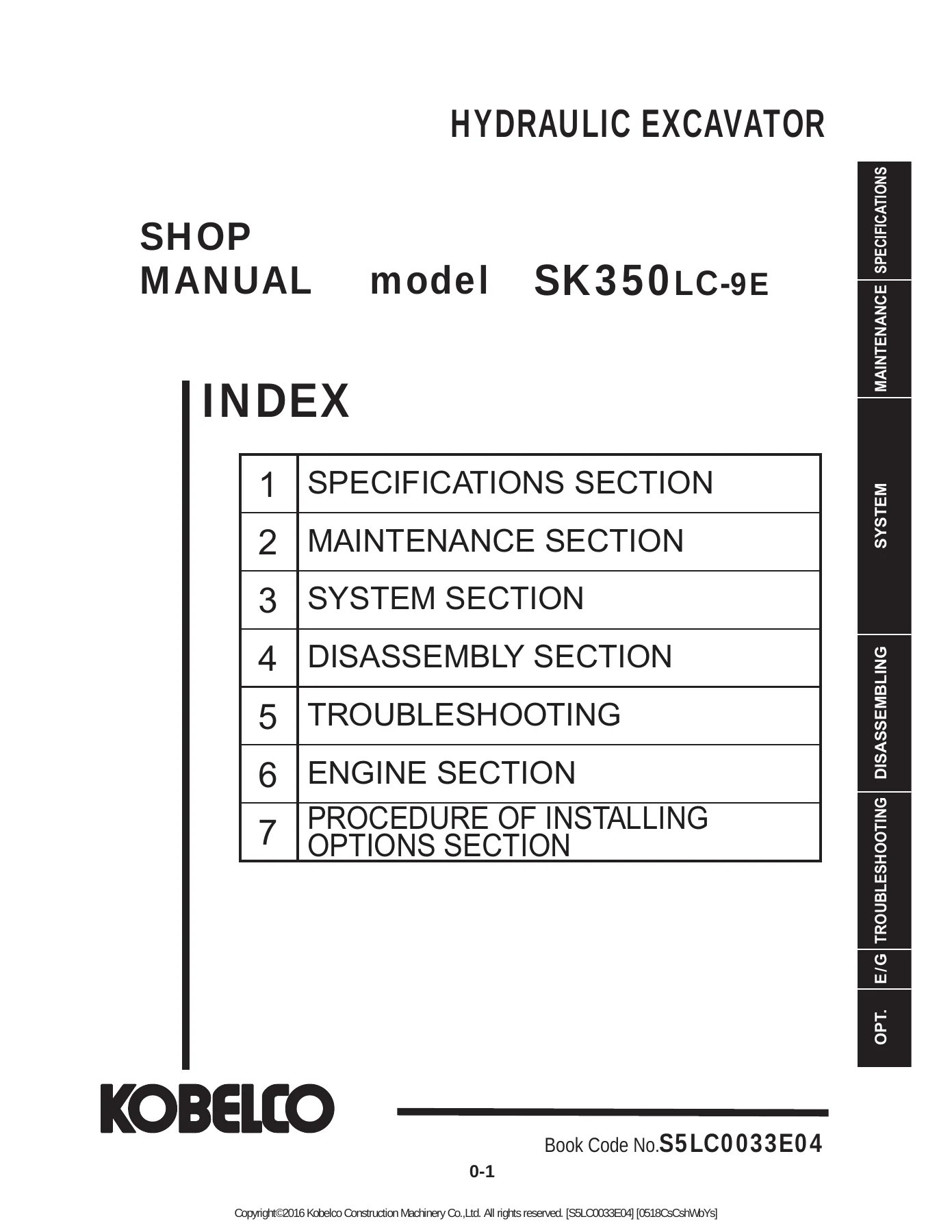
- 1. SPECIFICATIONS SECTION
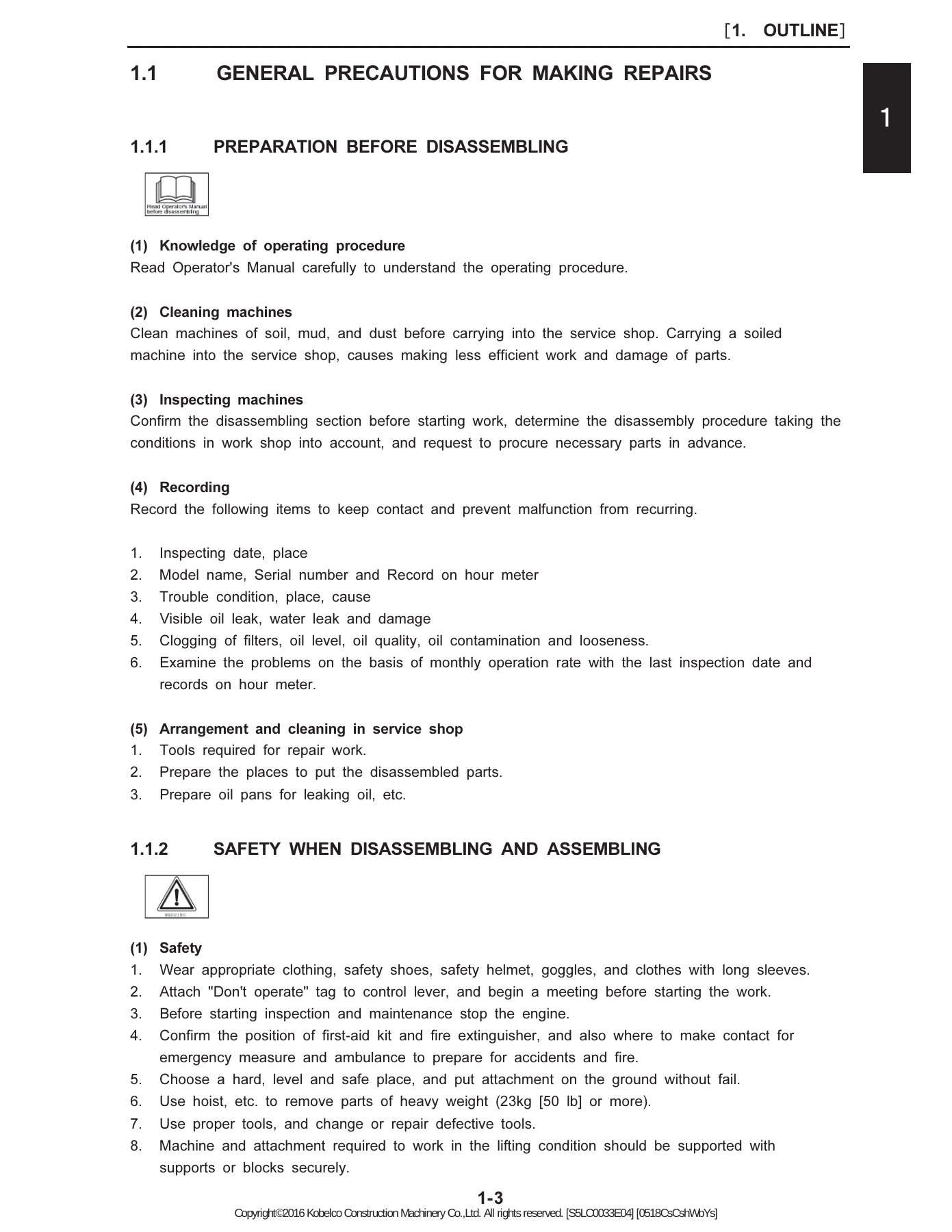
- 1. Outline (Book Code No. S5YN0129E01): General precautions for making repairs, workshop safety, preparation before disassembling, hydraulic equipment handling, electrical system safeguards, weld repair standards, environmental regulations, and SI international unit conversion tables.
- 2. Specifications (Book Code No. S5LC0233E01): Machine component nomenclature (40 primary items), general working dimensions (with 6.50 m boom, 3.30 m arm, and 1.40 m³ bucket), complete component weight breakdowns (upper structure, undercarriage, front attachment, and fluid weights), transportation dimensions on trailers, speed and climbing capabilities, engine performance curves, hydraulic component configurations, crawler shoe options (600 mm, 800 mm, and 900 mm grouser shoes), and bucket selection matrices.
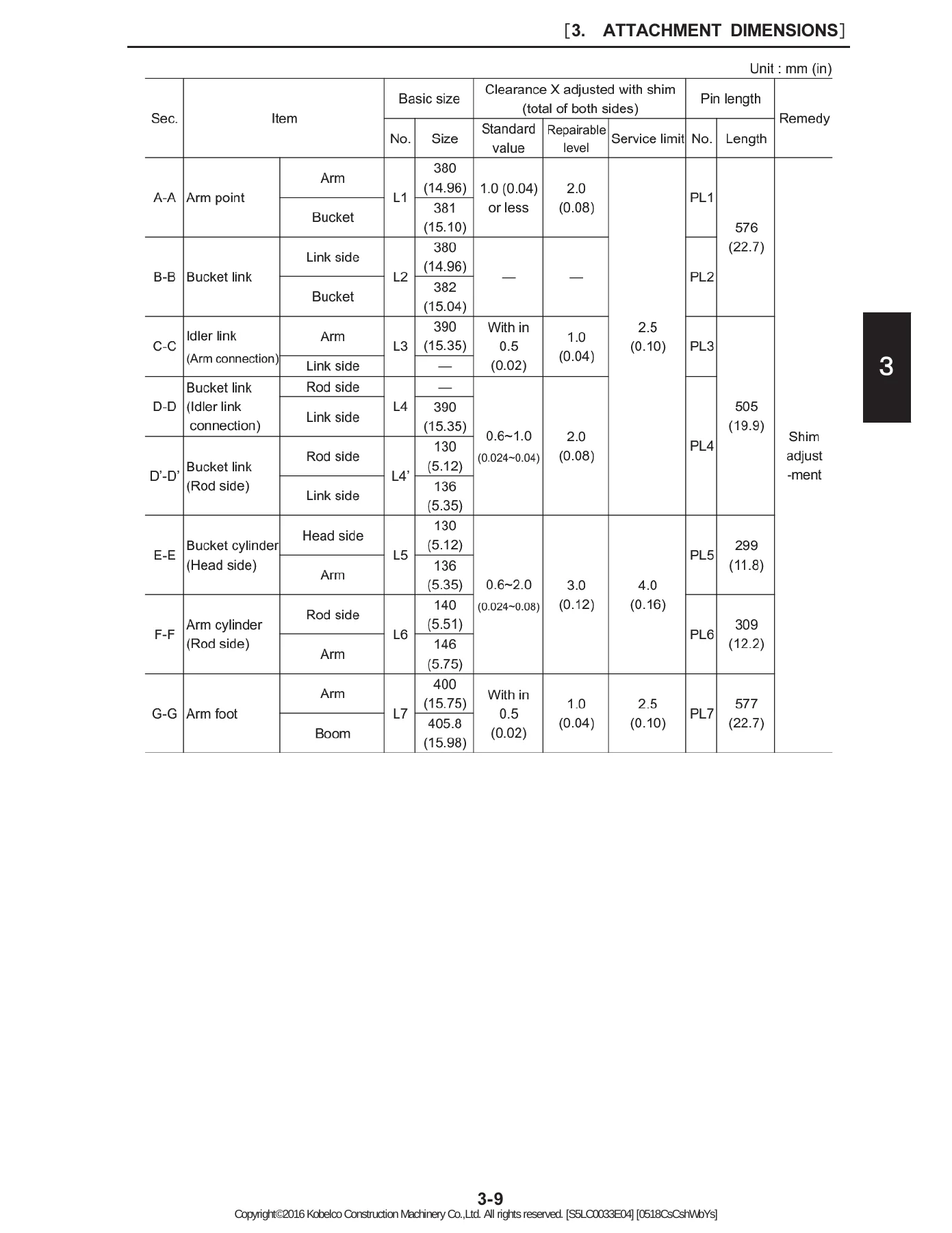
- 3. Attachment Dimensions (Book Code No. S5LC0332E01): Boom dimensional layouts, boom maintenance standards (pin and bushing wear limits for boom foot and cylinder pivots), arm dimensional layouts (2.6 m, 3.30 m, and 4.15 m arms), arm maintenance standards, thrust clearance shim adjustment tables, and bucket pin, boss, and lug dimension drawings.
- 2. MAINTENANCE SECTION
- 11. Tools (Book Code No. S5LC1133E01): Standard tightening torques for metric coarse threads (Grades 4.8T, 7T, and 10.9T lubricated and dry), metric fine threads, hex wrench drive socket sizes, hydraulic hose 30-degree flare fittings, O-ring face seal (ORS) joints, split flanges (standard 20.6 MPa and high-pressure 41.2 MPa series), flareless tube nuts and sleeves, hydraulic blanking plugs, special spanners, thread locking and sealing compounds (Loctite and Three-Bond specifications), and fabrication drawings for lifting rigs, wooden engine stands, and DEF tank jigs.
- 12. Standard Maintenance Time Schedule (Book Code No. S5LC1233E01): Standard working man-hour allowances for all machine repair groups (attachment, cab and guards, swing frame, travel system, electrical items, and HINO engine overhaul operations).
- 13. Maintenance Standard and Test Procedure (Book Code No. S5LC1333E03): Performance inspection standard criteria, engine speed test procedures, main circuit and pilot relief pressure checks and adjustment procedures, travel speed and track deviation measurements, travel motor drain rate testing, swing speed and mechanical brake testing, swing motor drain rate tests, cylinder cycle times and hydraulic cylinder drift checks, swing bearing axial play measurement with dial indicators, mechatro controller B/C calibration procedures, DPF soot combustion/regeneration protocols, and DEF/SCR selective catalytic reduction system diagnosis.
- 3. SYSTEM SECTION
- 21. Mechatro Control System (Book Code No. S5LC2133E01): Summary of electro-hydraulic control architecture, unload valve control, positive flow control, P-Q pump horsepower limiting control, boom up conflux control, arm-in recirculation and conflux control, arm-in anti-cavitation control, arm-out conflux control, bucket digging anti-cavitation control, swing priority control, travel straight control, pressure release mode, nibbler/breaker auxiliary hydraulic controls, multi-display gauge cluster functions, service diagnosis screens, and error code history.
- 22. Hydraulic System (Book Code No. S5LC2233E01): Complete hydraulic circuit schematics (drawing LC01Z00099P1), color-coded operating modes, neutral circuit bypass cut valve and unload valve operation, travel pilot and main drive circuits (auto 2-speed downshift), bucket digging and dumping circuits, boom raise conflux and boom lowering constant recirculation circuits, swing circuit with anti-cavitation makeup, arm circuit flow recirculation, combined operations, and pressure draining procedures.
- 23. Electric System (Book Code No. S5LC2333E01): Electrical schematics, wiring harness routing, relay and fuse box arrangements, sensor circuit diagrams, and controller communication networks.
- 24. Components System (Book Code No. S5LC2433E01): Hydraulic pump internal structure, main control valve spool layouts and check valves, swing motor and reduction gearbox, travel motor and planetary reduction assemblies, and hydraulic cylinder construction.
- 25. Air-Conditioner System (Book Code No. S5LC2525E01): Cab climate control circuits, compressor, condenser, receiver dryer, electronic amplifier, sensor inputs, and refrigerant charging.
IMAGES PREVIEW

- 4. DISASSEMBLY & ASSEMBLY SECTION
- 31. Disassembling & Assembling Procedures (Book Code No. S5YN3129E01): General disassembly rules, match-marking, cleaning, seal replacement, and hoisting precautions.
- 32. Attachment (Book Code No. S5LC3226E01): Removal and installation procedures for bucket, arm, boom, and corresponding hydraulic cylinders; pin and bushing replacement.
- 33. Upper Structure (Book Code No. S5LC3333E02): Removal and installation of operator cab, body panels and protective guards, counterweight (8,800 kg), engine assembly, radiator and hydraulic oil cooler pack, fuel tank, hydraulic oil tank, main hydraulic pump assembly, 8-spool main control valve, swing motor unit, swivel joint, and upper frame separation from lower frame.
- 34. Travel System (Book Code No. S5LC3432E03): Undercarriage track shoe and link disassembly, upper rollers, lower rollers, front idlers and hydraulic track tension adjusters, drive sprockets, travel motors with reduction units, and slewing bearing removal and installation.
- 5. TROUBLESHOOTING
- 46. Troubleshooting by Error Codes (Book Code No. S5LQ4636E01): Diagnostic fault isolation procedures for all mechatro controller error codes, sensor failures, proportional solenoid valve faults, and engine controller (ECU) trouble codes.
- 47. Troubleshooting by Trouble Symptoms (Book Code No. S5LC4732E02): Systematic mechanical, hydraulic, and electrical troubleshooting procedures categorized by machine operating symptoms.
- 6. ENGINE SECTION
- 51. Engine (Book Code No. S5LC5133E02): Comprehensive overhaul, maintenance, disassembly, inspection, reconditioning, and assembly manual for the HINO J08E-VV diesel engine.
- 7. PROCEDURE OF INSTALLING OPTIONS SECTION
- Mounting procedures, supplemental hydraulic line routings, auxiliary control valves, and electrical switch installations for optional demolition and utility attachments.
As a whole, this comprehensive technical documentation provides service personnel with the foundational knowledge and precise data required to maintain the Kobelco SK350LC-9E at peak performance. By detailing internal hydraulic spool interactions, mechatronic communication lines, exact wear limits, and overhaul sequences, this manual eliminates trial-and-error repairs and enables complete mechanical confidence during major overhauls.
Engine Specifications & Powertrain Management
The Kobelco SK350LC-9E Hydraulic Excavator is powered by the heavy-duty HINO J08E-VV direct-injection, water-cooled, 4-cycle, 6-cylinder diesel engine fitted with an air-to-air intercooled turbocharger. The displacement is 7.684 liters (7,684 cc / 468.9 cu-in) with a cylinder bore of 112 mm (4.41 in) and a piston stroke of 130 mm (5.12 in). Operating at a 17.0:1 compression ratio, the engine produces a rated power output of 213 kW (286 hp) at 2,100 rpm (ISO 14396 net without fan) or 201 kW (270 hp) at 2,100 rpm (ISO 9249 net). Peak torque delivery reaches 1,017 N·m (750 lbf·ft) at 1,600 rpm (ISO 14396) or 988 N·m (736 lbf·ft) (ISO 9249), providing massive lugging power for heavy trenching and rock extraction.
The fuel delivery system utilizes high-pressure common rail injection managed by an electronic engine control unit (ECU). The manual provides full technical specifications including an injection starting pressure of 3.2 MPa (464 psi), cylinder compression pressure ranging between 3.4 MPa and 3.7 MPa (493 to 537 psi) at 280 rpm, and a firing order of 1-4-2-6-3-5. Valve clearances when cold are specified at 0.30 mm for intake valves and 0.45 mm for exhaust valves. The cooling architecture utilizes an 850 mm (33.5 in) diameter 6-blade suction fan driven via V-belt with a crank-to-fan pulley ratio of 0.80, regulated by a thermostat initiating opening at 350 K (170°F) and reaching full opening at 363 K (194°F). Engine lubrication features a 28.5-liter total oil capacity (26.0 L high mark, 20.0 L low mark) designed to sustain operating inclinations up to 35 degrees in any direction.
Emissions compliance is achieved through integrated exhaust aftertreatment consisting of a Diesel Particulate Filter (DPF) and a Selective Catalytic Reduction (DEF/SCR) system. The manual provides precise maintenance and diagnostic parameters for soot accumulation management, detailing automatic regeneration cycles, safety interlock requirements for manual stationary regeneration, and mandatory DPF servicing intervals (inspection every 1,000 hours, differential pressure hose replacement every 2 years, and core cleaning or replacement at 4,500 operating hours). Additionally, complete service instructions cover the DEF supply module, dosing injectors, NOx sensors, DEF level sensors, quality de-rate prevention, anti-crystallization after-run purge operations, and emergency evacuation operating modes.
Electro-Hydraulic Architecture & Calibration
The primary hydraulic system utilizes two variable displacement axial piston pumps (Kawasaki K5V140DTP) coupled with a pilot gear pump, managed through an 8-spool monoblock/sectional main control valve (KMX15YE). Hydraulic circuit operating pressures are calibrated with extreme precision:
- Main Relief Valve (Standard): 34.3 MPa (4,970 psi)
- Main Relief Valve (Power Boost Activated): 37.8 MPa (5,480 psi)
- Boom, Arm, and Bucket Port Overload Relief Valves: 37.8 to 39.7 MPa (5,480 to 5,760 psi)
- Swing Overload Relief Pressure: 29.0 MPa (4,205 psi)
- Travel Overload Relief Pressure: 35.8 MPa (5,190 psi)
- Pilot Circuit Operating Pressure: 5.0 MPa (725 psi)
The Kobelco SK350LC-9E mechatronic control system continuously monitors pilot joystick demands via low-pressure sensors (SE-1 through SE-10) and main pump delivery pressures via high-pressure sensors (SE-22, SE-23). The mechatro controller processes these inputs to command proportional solenoid valves controlling pump swashplate angles (PSV-P1, PSV-P2) and control valve unload spools (PSV-D, PSV-B). This provides positive flow control that matches pump output instantaneously to lever displacement, paired with P-Q curve horsepower limiting that matches hydraulic power to available engine torque to prevent engine stalling under extreme loads.
Specialized internal control functions detailed in the hydraulic section include the Boom Up Conflux Circuit (combining flow from P1 and P2 pumps to accelerate lift cycles), Arm-In Recirculation and Conflux Control (recirculating return oil from the arm cylinder rod side into the head side while simultaneously combining pump flows to maximize digging speeds under low load), Arm-In Anti-Cavitation Control, Arm-Out Conflux Control, Bucket Digging Anti-Cavitation Control (utilizing travel straight valve engagement and pilot stroke limiting on the bucket spool to prevent cavitation when engine speed is low), Swing Priority Control (ensuring uninterrupted swing acceleration during combined arm-in and swing cycles), and Travel Straight Control (directing dedicated pump flow to tracking motors while front attachments operate independently). Technicians will find complete step-by-step procedures to perform the critical ‘B-Adjustment’ (pump output coordination) and ‘C-Adjustment’ (unloading valve calibration) directly through the in-cab gauge cluster display without requiring external service software.
Maintenance Standards & Assembly Clearances
To support precision overhauls, the Kobelco SK350LC-9E Hydraulic Excavator Shop Manual S5LC0033E04 incorporates extensive maintenance standard tables providing nominal dimensions, manufacturing tolerances, repairable limits, and absolute service limits for major structural pivots and running gear. Attachment pin and bushing wear limits cover the 110 mm boom foot pin, 100 mm boom cylinder head pin, 110 mm boom cylinder rod pin, 110 mm arm cylinder head pin, 90 mm arm point pin, and 80 mm/90 mm bucket linkage pins, establishing standard radial clearances of 0.078 to 0.250 mm with a maximum allowable service limit of 2.5 mm to 3.0 mm before replacement is mandatory.
Thrust clearances and shim adjustment criteria are comprehensively tabulated for all cylinder mounting bosses and attachment hinge points. Undercarriage wear monitoring procedures cover track link pitch elongation, track roller flanges, front idler guide clearances, sprocket tooth profiles, and slewing ring bearing play. Complete measurement instructions guide the technician in utilizing a magnetic base and dial indicator to verify slewing bearing axial clearance, where the standard play is 0.8 mm to 1.8 mm (0.03 to 0.07 in), the repairable threshold is 2.3 mm to 3.3 mm (0.09 to 0.13 in), and the absolute service replacement limit is 3.6 mm (0.14 in).
Fastener security is addressed through exhaustive torque specifications detailing standard tightening values for metric coarse and fine fasteners across strength grades 4.8T, 7T, and 10.9T under both dry and oil-lubricated conditions. Specific torque and assembly instructions are provided for hydraulic fittings, including 30-degree flare nuts, ORS sleeve fittings, split flange clamp halves, and flareless compression sleeve joints. The manual also includes dimensional blueprints and material schedules allowing shop personnel to fabricate custom service tools, such as the upper frame three-point lifting sling assembly, wooden engine overhaul bench stand, DEF tank fixing band whirl-stop tool, and hydraulic tank suction stopper.
Professional Capability, Equipment Protection & Digital Delivery
Possessing the official Kobelco SK350LC-9E Hydraulic Excavator Shop Manual S5LC0033E04 equips repair technicians, field mechanics, and fleet managers with the technical capabilities required to execute everything from routine hydraulic pressure calibrations to complete machine rebuilds. Rather than relying on guesswork or generic repair methods, this manual ensures every bolt torque, valve adjustment, pump calibration, and electrical test strictly complies with official factory engineering standards. Adhering to these documented factory procedures protects complex hydraulic components from cavitation damage, safeguards high-pressure common rail fuel systems, prevents structural failure, and significantly lowers equipment lifecycle maintenance costs.
This shop manual is delivered as an instant PDF download immediately upon checkout. With no waiting for physical shipping, you can access crucial technical data instantly on your laptop, tablet, desktop computer, or smartphone across Windows, macOS, Android, and iOS devices. The high-resolution digital format allows you to zoom into microscopic details on electrical schematics and hydraulic circuit drawings, search instantly for part numbers or error codes, and print clean copies of specific repair sections, wiring diagrams, or torque tables directly for hands-on use in the service bay or out in the field.

Reviews
There are no reviews yet.