Komatsu 125E-5 Series Diesel Engine Shop Manual – PDF DOWNLOAD
Original price was: $63.95.$30.95Current price is: $30.95.
Komatsu 125E-5 Series Diesel Engine Shop Manual
Book Code: SEN00177-14
Description
Komatsu 125E-5 Series Diesel Engine Shop Manual
FILE DETAILS:
Komatsu 125E-5 Series Diesel Engine Shop Manual
Brands: Komatsu
Equipment Type: Diesel Engine
Manuals Type: Shop Manual
Machine Model: 125E-5 Series Engine
Book Code: SEN00177-14
Language: English
Pages: 647
File Format: Portable Document Format (PDF)
KOMATSU 125E-5 SERIES DIESEL ENGINE SHOP MANUAL – PDF DOWNLOAD:
IMAGES PREVIEW OF THE MANUAL:
DESCRIPTION:
Komatsu 125E-5 Series Diesel Engine Shop Manual
How to read the shop manual:
1. Composition of shop manual:
This shop manual contains the necessary technical information for services performed in a workshop. For ease of understanding, the manual is divided into the following sections.
00. Index and foreword:
This section explains the shop manuals list, table of contents, safety, and basic information.
01. Specification:
This section explains the specifications of the machine.
10. Structure, function and maintenance standard:
This section explains the structure, function, and maintenance standard values of each component. The structure and function sub-section explains the structure and function of each component. It serves not only to give an understanding of the structure, but also serves as reference material for troubleshooting. The maintenance standard sub-section explains the criteria and remedies for disassembly and service.
20. Standard value table:
This section explains the standard values for new machine and judgement criteria for testing, adjusting, and troubleshooting. This standard value table is used to check the standard values in testing and adjusting and to judge parts in troubleshooting.
30. Testing and adjusting:
This section explains measuring instruments and measuring methods for testing and adjusting, and method of adjusting each part. The standard values and judgement criteria for testing and adjusting are explained in Testing and adjusting.
40. Troubleshooting:
This section explains how to find out failed parts and how to repair them. The troubleshooting is divided by failure modes. The “S mode” of the troubleshooting related to the engine may be also explained in the Chassis volume and Engine volume. In this case, see the Chassis volume.
50. Disassembly and assembly:
This section explains the special tools and procedures for removing, installing, disassembling, and assembling each component, as well as precautions for them. In addition, tightening torque and quantity and weight of coating material, oil, grease, and coolant necessary for the work are also explained.
90. Diagrams and drawings (chassis volume)/Repair and replacement of parts (engine volume):
- Chassis volume
This section gives hydraulic circuit diagrams and electrical circuit diagrams. - Engine volume
This section explains the method of reproducing, repairing, and replacing parts.
TABLE OF CONTENTS:
Komatsu 125E-5 Series Diesel Engine Shop Manual
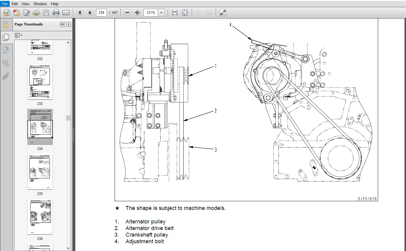
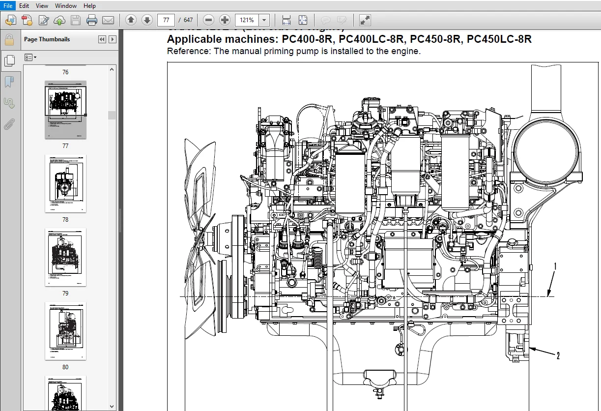
COVER
....................................................................................  1
00 Index and foreword.....................................................................  0
	Index.................................................................................  4
		Composition of shop manual........................................................  5
		Table of contents.................................................................  6
	Foreword and general information...................................................... 12
		Safety notice..................................................................... 13
		How to read the shop manual....................................................... 18
		Explanation of terms for maintenance standard..................................... 20
		Handling of electric equipment and hydraulic component............................ 22
		Handling of connectors newly used for engines..................................... 31
		How to read electric wire code.................................................... 34
		Precautions when carrying out operation........................................... 37
		Method of disassembling and connecting push-pull type coupler..................... 40
		Standard tightening torque table.................................................. 43
		Conversion table.................................................................. 47
01 Specification..........................................................................  0
	Specification and technical data...................................................... 54
		Outline........................................................................... 55
		Specifications.................................................................... 59
		General view...................................................................... 73
		Weight table...................................................................... 98
		Engine performance curves.........................................................101
10 Structure, function and maintenance standard...........................................  0
	Structure, function and maintenance standard, Part 1..................................110
		General structure.................................................................113
		Air intake and exhaust unit.......................................................115
		Air cleaner.......................................................................119
		Turbocharger......................................................................121
		Aftercooler.......................................................................128
		EGR system........................................................................129
		Cylinder head.....................................................................136
		Cylinder block....................................................................139
		Cylinder liner....................................................................143
		Main moving parts.................................................................144
		Crankshaft........................................................................146
		Camshaft..........................................................................147
		Cam follower and push rod.........................................................148
		Piston, piston ring and piston pin................................................149
		Connecting rod....................................................................151
		Flywheel and flywheel housing.....................................................152
		Vibration damper..................................................................157
		Timing gear.......................................................................159
		Valve system......................................................................167
		Valve and valve guide.............................................................171
		Rocker arm and shaft..............................................................173
		Crosshead and guide...............................................................174
	Structure, function and maintenance standard, Part 2..................................176
		Lubrication system................................................................179
			Lubrication system diagram....................................................179
			Oil pump......................................................................183
			Main relief valve.............................................................184
			EGR oil pump..................................................................185
			Oil filter....................................................................186
			Safety valve..................................................................188
			Oil cooler....................................................................189
		Fuel system.......................................................................191
			CRI system diagram............................................................191
			Outline of CRI system.........................................................193
			Fuel piping...................................................................215
			Fuel cooler...................................................................217
			Fuel filter...................................................................218
			Electric priming pump.........................................................220
			Engine controller cooler......................................................221
		Cooling system....................................................................223
			Cooling system diagram........................................................223
			Water pump....................................................................225
			Thermostat....................................................................227
			Corrosion resistor............................................................229
		Electrical equipment..............................................................230
			Alternator....................................................................230
			Starting motor................................................................237
			Electrical intake air heater..................................................241
			Engine controller.............................................................242
20 Standard value table...................................................................  0
	Standard service value table..........................................................244
		Standard service value table......................................................245
			Standard service value table for testing, adjusting, and troubleshooting......245
			Running-in standard and performance test standard.............................258
30 Testing and adjusting..................................................................  0
	Testing and adjusting.................................................................268
		Testing and adjusting (With EGR)..................................................270
			Testing and adjusting tools list..............................................270
			Sketches of special tools.....................................................272
			Testing air boost pressure....................................................273
			Testing exhaust temperature...................................................274
			Adjusting valve clearance.....................................................275
			Testing compression pressure..................................................276
			Testing blow-by pressure......................................................278
			Testing engine oil pressure...................................................279
			Measuring EGR valve and bypass valve drive pressure...........................280
			Handling fuel system parts....................................................281
			Releasing residual pressure in fuel system....................................281
			Testing fuel pressure.........................................................282
			Reduced cylinder mode operation...............................................283
			No-injection cranking.........................................................283
			Testing leakage from pressure limiter and return rate from injector...........284
			Bleeding air from fuel circuit................................................287
			Testing fuel system for leakage...............................................289
			Adjusting speed sensor........................................................290
			Testing and adjusting alternator belt tension.................................291
			Handling controller voltage circuit...........................................292
		Testing and adjusting (EGR-less)..................................................293
			Testing and adjusting tools list..............................................293
			Sketches of special tools.....................................................295
			Testing air boost pressure....................................................296
			Testing exhaust temperature...................................................297
			Adjusting valve clearance.....................................................298
			Testing compression pressure..................................................299
			Testing blow-by pressure......................................................301
			Testing engine oil pressure...................................................302
			Handling fuel system parts....................................................303
			Releasing residual pressure in fuel system....................................303
			Testing fuel pressure.........................................................304
			Reduced cylinder mode operation...............................................305
			No-injection cranking.........................................................305
			Testing leakage from pressure limiter and return rate from injector...........306
			Bleeding air from fuel circuit................................................308
			Testing fuel system for leakage...............................................310
			Adjusting speed sensor........................................................311
			Testing and adjusting alternator belt tension.................................312
			Handling controller voltage circuit...........................................313
40 Troubleshooting........................................................................  0
	General information on troubleshooting................................................316
		General information on troubleshooting............................................317
			Points on troubleshooting.....................................................317
			Error code and failure code table.............................................319
			Information in troubleshooting table..........................................323
	Troubleshooting of electrical system (E-mode), Part 1.................................326
		Troubleshooting of electrical system (E-mode), Part 1.............................329
			E-1 Code [111/CA111] ECM Critical Internal Failure............................329
			E-2 Code [115/CA115] Eng. Ne and Bkup Speed Sensor Error......................331
			E-3 Code [122/CA122] Charge Air Press Sensor High Error.......................333
			E-4 Code [123/CA123] Charge Air Press Sensor Low Error........................335
			E-5 Code [131/CA131] Throttle Sensor High Error...............................337
			E-6 Code [132/CA132] Throttle Sensor Low Error................................341
			E-7 Code [135/CA135] Oil press. Sensor High Error.............................343
			E-8 Code [141/CA141] Oil press. Sensor Low Error..............................345
			E-9 Code [144/CA144] Coolant Temp. Sensor High Error..........................347
			E-10 Code [145/CA145] Coolant Temp. Sensor Low Error..........................349
			E-11 Code [153/CA153] Charge Air Temp. Sensor High Error......................351
			E-12 Code [154/CA154] Charge Air Temp. Sensor Low Error.......................353
			E-13 Code [187/CA187] Sensor Sup. 2 Volt. Low Error...........................354
			E-14 Code [221/CA221] Ambient Air Press. Sensor High Error....................355
			E-15 Code [222/CA222] Ambient Air Press. Sensor Low Error.....................357
			E-16 Code [227/CA227] Sensor Sup. 2 Volt. High Error..........................359
			E-17 Code [234/CA234] Eng. Overspeed..........................................361
			E-18 Code [238/CA238] Ne Speed Sensor Sup. Volt. Error........................363
			E-19 Code [263/CA263] Fuel Temp. Sensor High Error............................365
			E-20 Code [265/CA265] Fuel Temp. Sensor Low Error.............................367
			E-21 Code [271/CA271] PCV1 Short Error........................................369
			E-22 Code [272/CA272] PCV1 Open Error.........................................371
			E-23 Code [273/CA273] PCV2 Short Error........................................373
			E-24 Code [274/CA274] PCV2 Open Error.........................................375
			E-25 Code [322/CA322] Injector #1 (L/B #1) System Open/Short Error............377
			E-26 Code [323/CA323] Injector #5 (L/B #5) System Open/Short Error............379
			E-27 Code [324/CA324] Injector #3 (L/B #3) System Open/Short Error............381
			E-28 Code [325/CA325] Injector #6 (L/B #6) System Open/Short Error............383
			E-29 Code [331/CA331] Injector #2 (L/B #2) System Open/Short Error............385
			E-30 Code [332/CA332] Injector #4 (L/B #4) System Open/Short Error............387
			E-31 Code [342/CA342] Calibration Code Incompatibility........................389
			E-32 Code [351/CA351] INJ. Drive Circuit Error................................391
			E-33 Code [352/CA352] Sensor Sup. 1 Volt. Low Error...........................393
			E-34 Code [386/CA386] Sensor Sup. 1 Volt. High Error..........................395
			E-35 Code [431/CA431] Idle Validation SW Low error............................397
			E-36 Code [432/CA432] Idle Validation Process error...........................399
			E-37 Code [441/CA441] Battery voltage low error...............................399
			E-38 Code [442/CA442] Battery voltage high error..............................400
	Troubleshooting of electrical system (E-mode), Part 2.................................402
		Troubleshooting of electrical system (E-mode), Part 2.............................404
			E-39 Code [449/CA449] Rail Press. Very High Error.............................404
			E-40 Code [451/CA451] Rail Press. Sensor High Error...........................405
			E-41 Code [452/CA452] Rail Press. Sensor Low Error............................407
			E-42 Code [553/CA553] Rail Press. High Error..................................407
			E-43 Code [554/CA554] Rail Press Sensor In Range Error........................408
			E-44 Code [559/CA559] Rail Press. Low Error...................................409
			E-45 Code [689/CA689] Eng. Ne Speed Sensor Error..............................413
			E-46 Code [731/CA731] Eng. Bkup Speed Sensor Phase Error......................415
			E-47 Code [757/CA757] All Persistent Data Lost Error..........................416
			E-48 Code [778/CA778] Eng. Bkup Speed Sensor Error............................417
			E-49 Code [1228/CA1228] EGR Valve Servo Error 1...............................419
			E-50 Code [1625/CA1625] EGR Valve Servo Error 2...............................420
			E-51 Code [1626/CA1626] Bypass Valve Solenoid Current High Error..............421
			E-52 Code [1627/CA1627] Bypass Valve Solenoid Current Low Error...............423
			E-53 Code [1628/CA1628] Bypass Valve Servo Error 1............................424
			E-54 Code [1629/CA1629] Bypass Valve Servo Error 2............................425
			E-55 Code [1631/CA1631] BP valve Lift Position Sensor High Error..............427
			E-56 Code [1632/CA1632] BP valve Lift Position Sensor Low Error...............429
			E-57 Code [1633/CA1633] KOMNET Datalink Timeout Error.........................429
			E-58 Code [1642/CA1642] EGR Inlet Press Sensor Low Error......................430
			E-59 Code [1653/CA1653] EGR Inlet Press Sensor High Error.....................431
			E-60 Code [2185/CA2185] Throttle Sens. Sup. Volt. High Error..................433
			E-61 Code [2186/CA2186] Throttle Sens. Sup. Volt. Low Error...................437
			E-62 Code [2249/CA2249] Rail Press. Very Low Error............................438
			E-63 Code [2271/CA2271] EGR Valve Lift Position Sensor High Error.............439
			E-64 Code [2272/CA2272] EGR Valve Lift Position Sensor Low Error..............441
			E-65 Code [2351/CA2351] EGR Valve Solenoid Current High Error.................443
			E-66 Code [2352/CA2352] EGR Valve Solenoid Current Low Error..................445
			E-67 Code [2555/CA2555] Grid Heater Relay Volt. Low Error.....................446
			E-68 Code [2556/CA2556] Grid Heater Relay Volt. High Error....................447
			E-69 Code [(143)/B@BAZG] Eng. Oil press. Torque Derate........................449
			E-70 Code [(146)/B@BCNS] Eng. Overheat........................................449
			E-71 Code [(415)/B@BAZG] Eng. Oil press. Low Speed Derate.....................450
	Troubleshooting of mechanical system (S-mode).........................................452
		Troubleshooting of mechanical system (S-mode).....................................455
			Method of using troubleshooting charts........................................455
			S-1 Starting performance is poor..............................................459
			S-2 Engine does not start.....................................................461
			S-3 Engine does not pick up smoothly..........................................465
			S-4 Engine stops during operations............................................466
			S-5 Engine does not rotate smoothly...........................................467
			S-6 Engine lacks output (or lacks power)......................................468
			S-7 Exhaust smoke is black (incomplete combustion)............................469
			S-8 Oil consumption is excessive (or exhaust smoke is blue)...................471
			S-9 Oil becomes contaminated quickly..........................................472
			S-10 Fuel consumption is excessive............................................473
			S-11 Oil is in coolant (or coolant spurts back or coolant level goes down)....474
			S-12 Oil pressure drops.......................................................475
			S-13 Oil level rises (Entry of coolant or fuel)...............................476
			S-14 Coolant temperature becomes too high (overheating).......................478
			S-15 Abnormal noise is made...................................................479
			S-16 Vibration is excessive...................................................480
50 Disassembly and assembly...............................................................  0
	General information on disassembly and assembly.......................................482
		General information on disassembly and assembly...................................483
			How to read this manual.......................................................483
			Coating materials list........................................................485
			Special tools list............................................................488
	Disassembly and assembly, Part 1 (With EGR)...........................................490
		Disassembly and assembly, Part 1 (With EGR).......................................491
			General disassembly of engine.................................................491
			General assembly of engine....................................................506
	Disassembly and assembly, Part 2 (EGR-less)...........................................538
		Disassembly and assembly, Part 2 (EGR-less).......................................539
			General disassembly of engine.................................................539
			General assembly of engine....................................................553
	Disassembly and assembly, Part 3......................................................586
		Disassembly and assembly, Part 3..................................................587
			Removal and installation of fuel supply pump unit.............................587
			Replacement of oil seal of engine mounted on machine..........................589
90 Repair and replacement of parts........................................................  0
	Information related to repair and replacement.........................................594
		Flowchart.........................................................................595
		Special tool table................................................................597
		Special tool sketch...............................................................599
	Parts related to cylinder head........................................................602
		Part names related to cylinder head...............................................603
		Testing and inspection of cylinder head...........................................604
		Pressure test of cylinder head....................................................606
		Replacement of valve guide........................................................606
		Replacement of valve seat insert..................................................607
		Replacement of crosshead guide....................................................614
		Repair of valve by grinding.......................................................615
	Parts related to cylinder block.......................................................618
		Part names related to cylinder block..............................................619
		Testing and inspection of cylinder block..........................................620
		Part names related to crankshaft..................................................623
		Testing and inspection of crankshaft..............................................624
		Part names related to connecting rod..............................................625
		Testing and inspection of connecting rod..........................................626
		Replacement of flywheel ring gear.................................................628
		Replacement of camshaft gear......................................................628
		Replacement of main bearing metal cap.............................................629
		Replacement of connecting rod small end bushing...................................631
		Replacement of cam bushing........................................................632
		Replacement of engine rear seal...................................................634
		Replacement of wear sleeve (when sleeve is installed).............................638
		Repair of crankshaft by grinding..................................................639
PLEASE NOTE:
- This is the same manual used by the DEALERSHIPS to SERVICE your vehicle.
- The manual can be all yours – Once payment is complete, you will be taken to the download page from where you can download the manual. All in 2-5 minutes time!!
- Need any other service / repair / parts manual, please feel free to contact us at heydownloadss @gmail.com . We may surprise you with a nice offer


Alberto Anthony –
All are OK OK.