
Komatsu 125E-7 Series SAA6D125E-7 Engine Shop Manual SEN06495-06 PDF Download
Original price was: $67.95.$44.95Current price is: $44.95.
Complete Komatsu 125E-7 Series engine shop manual for the SAA6D125E-7 diesel engine — form number SEN06495-06. Full specifications, structure and function, standard value tables, disassembly and assembly procedures, and maintenance standards for D85EX-18, D85PX-18, HM300-5, PC490LC-11 and WA470-8 machines.
Description
Komatsu 125E-7 Series Engine Shop Manual — SAA6D125E-7 · SEN06495-06
This is the complete Komatsu 125E-7 Series Engine Shop Manual for the SAA6D125E-7 diesel engine, issued under form number SEN06495-06. It is the workshop reference used for every major engine procedure on the 125E-7 Series — from routine specification checks and standard-value comparisons through full teardown, component inspection, and reassembly. Every chapter of the original document is present: Index and Foreword, Specifications, Structure and Function, Standard Value Table, Disassembly and Assembly, and Maintenance Standard.
File Details
- Manual type: Engine Shop Manual
- Brand: Komatsu
- Engine model: SAA6D125E-7
- Engine series: 125E-7 Series
- Document number: SEN06495-06
- Publication date: 11-2015
- Language: English
- File format: PDF
- Page count: 478 pages
Chapters Covered
- 00 — Index and Foreword
- 01 — Specifications
- 10 — Structure and Function
- 20 — Standard Value Table
- 50 — Disassembly and Assembly
- 60 — Maintenance Standard
00 — Index and Foreword
Abbreviation lists covering both the text and the circuit diagrams (CRI, KVGT, KDPF, SCR, EGR, KCCV, and the rest of the emissions-control abbreviations used throughout the manual), the complete safety notice for operation, fire-prevention precautions and fire-response procedures, waste-disposal requirements, and the actions taken to meet exhaust gas regulations. DEF/AdBlue handling and storage guidance — including freeze points, storage periods at temperature, and cold-weather practice — is here. So are the detailed working precautions for hydraulic equipment, disconnecting and connecting pipings, electrical equipment, fuel system equipment, and intake system equipment, plus step-by-step procedures for push-pull type couplers (Types 1, 2 and 3), Deutsch connectors, slide-lock connectors, lock-to-pull and lock-to-push connectors, and rotating-housing connectors. The chapter closes with electrical wire code reading, an explanation of the terms used in the maintenance standards, the standard tightening torque tables, and unit conversion tables.
01 — Specifications
Engine specifications for the SAA6D125E-7 across the four machine families it powers. General specifications (bore and stroke, piston displacement, firing order, dimension and weight data, rated horsepower and torque, high and low idle speeds, fuel consumption ratios, lubricating oil and coolant capacities, alternator and starter motor ratings, and turbocharger model), the outline of the exhaust gas regulation the engine conforms to, a list of applicable machines, an engine general view for each model, the weight table, and engine performance curves. There is no ambiguity about which rated output belongs to which machine — the tables separate the D85EX-18 / D85EXI-18 / D85PX-18 / D85PXI-18, HM300-5, PC490LC-11 / PC490LCI-11, and WA470-8.
10 — Structure and Function
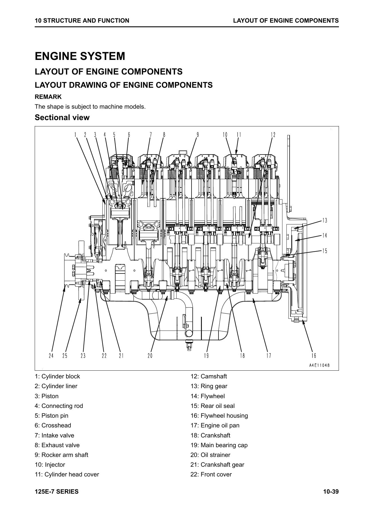
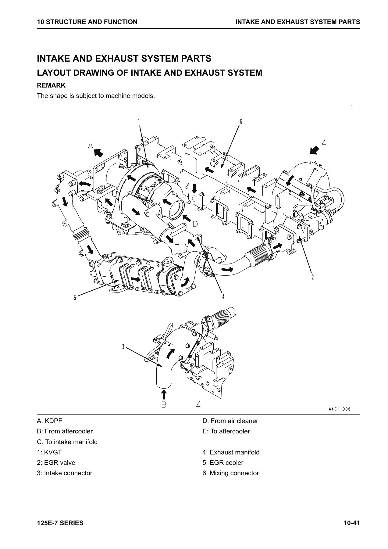
The largest chapter in the manual, and the one most useful for troubleshooting. It opens with the Urea SCR system — its layout drawing, system diagram, function, and component parts (AdBlue/DEF mixing tube, SCR assembly, AdBlue/DEF tank, tank sensor, pump, injector, hose, and tank heating valve) — then moves through the engine system itself: layout of engine components, intake and exhaust system parts, engine main body parts, the KVGT system, lubrication system, fuel system, cooling system, and electrical system. Each component gets its own structure, function, and operation breakdown: the air cleaner, cylinder head, cylinder block, main moving parts and the FCD piston, piston rings, vibration damper, timing gear, front cover, valve system, flywheel and flywheel housing, KVGT control system, EGR valve and EGR cooler, mixing connector, KCCV system and KCCV ventilator, KDPF, engine oil pump and engine boost oil pump, engine oil filter and oil cooler, fuel system and CRI system, supply pump, common rail, flow damper, pressure limiter, injector, fuel dosing system, fuel doser, fuel prefilter and main filter, water pump, thermostat, alternator, starting motor, engine wiring harness, engine controller, and the full sensor set. Wiring and system diagrams are included throughout.
20 — Standard Value Table
Performance standard values for a new engine and repair limits for each machine family using the SAA6D125E-7. It covers engine speed (high idle and low idle) on each application, air intake and exhaust system values (air intake resistance, boost pressure, exhaust temperature, exhaust gas colour at engine outlet and SCR outlet, valve clearance, EGR valve oil pressure and KVGT oil pressure at high and low idle), main body values (compression pressure, blowby pressure), lubrication system values (engine oil pressure at rated horsepower and at low idle, engine oil temperature, oil consumption), and electrical system values (alternator belt tension). Running-in standards and performance test standards follow, again broken out by machine model — running-in time, engine speed, dynamometer load, output, and dynamometer test values for rated horsepower, maximum torque, and high/low idle speeds.
50 — Disassembly and Assembly
The procedural heart of the manual. It begins with the related information section — how to read the manual, the coating materials list, the special tools list, and sketches of the special tools — then moves into general engine disassembly and assembly, supply pump assembly removal and installation, and engine front and rear oil seal removal and installation. The general engine disassembly procedure walks through preparation and draining, the starting motor, alternator and auto-tensioner, KVGT hydraulic actuator oil tube, EGR cooler, KVGT and exhaust manifold assembly, wiring harness, oil filter, fuel prefilter and fuel filter, fuel doser solenoid valve assembly, KCCV ventilator, EGR valve, mixing connector, fuel spill tube, fuel high-pressure pipes, air intake manifold, engine controller and cooler, common rail, supply pump assembly, fuel block, dipstick pipe, oil cooler assembly, cylinder head cover, fuel injector wiring harness, rocker arm and shaft assembly, push rods, fuel injectors, crossheads, rocker arm housing, thermostat housing and water pump, front hanger, cam follower cover and cam follower, cylinder head assembly, engine repair stand installation, speed sensors, engine oil pan and oil strainer, flywheel, flywheel housing, engine rear oil seal, damper and pulley assembly, front support, boost pump and EPC valve, front cover, engine front oil seal, camshaft, idler gears, engine oil pump, piston cooling nozzles, piston and connecting rod assemblies, crankshaft, and cylinder liners. The assembly side reverses the process with full tightening torque and angle-tightening guidance. The supply pump removal and installation and the front and rear oil seal procedures follow as their own sections with step-by-step tools and torque values.
60 — Maintenance Standard
The inspection-and-judgement chapter. It lists the wear limits, clearances, tolerances, and repair limits for the components a technician will actually measure — KVGT (radial play, end play, and the KVGT operation check through active regeneration for service), cylinder head, cylinder block, cylinder liner, crankshaft, cam follower and push rod, piston, connecting rod, vibration damper, timing gear, camshaft, valve and valve guide, rocker arm, crosshead and guide, flywheel, plus the lubrication and cooling system components (engine oil pump relief valve, engine boost oil pump relief valve, engine oil filter safety valve, engine oil cooler, water pump, and thermostat). Each entry gives the standard dimension, tolerance, and repair limit so you can decide whether to replace or reuse a part, not just guess at it.
What This 125E-7 Engine Shop Manual Lets You Do
The 125E-7 Series engine is a Tier 4 Final / Stage IV common-rail diesel with an aftertreatment stack that includes KVGT, EGR, KDPF, and SCR. Getting it wrong — guessing at a valve clearance, reusing a torque-plus-angle bolt past its limit, missing a fuel high-pressure pipe taper seal defect, or misreading an EGR or KVGT fault — is expensive. This manual gives you the exact figures and the exact sequences:
- Set valve clearance precisely (intake 0.33 mm, exhaust 0.71 mm) and torque the locknut to 58.8–73.5 Nm.
- Torque the cylinder head bolts in the correct order and to the correct step values, with the 90–120° angle re-tighten.
- Measure cylinder liner projection (0.07–0.15 mm), piston head protrusion (0.984–1.335 mm), crankshaft end play (0.140–0.315 mm), and connecting rod side clearance (0.2–0.375 mm) against the maintenance standards.
- Identify when a main cap bolt, connecting rod bolt, or flywheel bolt has reached its reuse limit by stem length and punch-mark count.
- Remove and reinstall the supply pump with the correct timing-mark alignment and mounting nut torque.
- Diagnose the Urea SCR system from the Inducement strategy tables, the AdBlue/DEF level warnings, and the EGR / KDPF / SCR failure code categories.
- Replace the front and rear oil seals using the standard or sleeved oil seal options, with the exact press-fitting distance and tooling.
IMAGES PREVIEW
Instant PDF Delivery
The Komatsu SEN06495-06 engine shop manual is delivered as a downloadable PDF the moment your order completes. No shipping, no waiting. Open it on a laptop in the workshop, a tablet next to the machine, or print whichever pages you want to take under the hood. Because it is one continuous PDF, you can search by component name, jump directly to a chapter, and keep the full torque tables and wear limits beside you while you work — exactly how a shop manual is meant to be used.

Reviews
There are no reviews yet.