KOMATSU 140E-5 SERIES SERVICE REPAIR MANUAL (SEN00074-16) – PDF Download
Original price was: $67.95.$26.95Current price is: $26.95.
- KOMATSU 140E-5 SERIES SERVICE REPAIR MANUAL
- PUBLICATION NUMBER:SEN00074-16
Description
KOMATSU 140E-5 SERIES SERVICE REPAIR MANUAL (SEN00074-16)
KOMATSU 140E-5 SERIES SERVICE REPAIR MANUAL (SEN00074-16) – PDF DOWNLOAD:
IMAGE PREVIEW:
DESCRIPTION:
KOMATSU 140E-5 SERIES SERVICE REPAIR MANUAL (SEN00074-16)
This shop manual contains the necessary technical information for services performed in a workshop. For ease of understanding, the manual is divided into the following sections.
00. Index and foreword
This section explains the shop manuals list, table of contents, safety, and basic information.
01. Specification
This section explains the specifications of the machine.
10. Structure, function and maintenance standard
This section explains the structure, function, and maintenance standard values of each component. The structure and function sub-section explains the structure and function of each component. It serves not only to give an understanding of the structure, but also serves as reference material for troubleshooting. The maintenance standard sub-section explains the criteria and remedies for disassembly and service.
20. Standard value table
This section explains the standard values for new machine and judgement criteria for testing, adjusting, and troubleshooting. This standard value table is used to check the standard values in testing and adjusting and to judge parts in troubleshooting.
30. Testing and adjusting
This section explains measuring instruments and measuring methods for testing and adjusting, and method of adjusting each part. The standard values and judgement criteria for testing and adjusting are explained in Testing and adjusting.
40. Troubleshooting
This section explains how to find out failed parts and how to repair them. The troubleshooting is divided by failure modes. The “S mode” of the troubleshooting related to the engine may be also explained in the Chassis volume and Engine volume. In this case, see the Chassis volume.
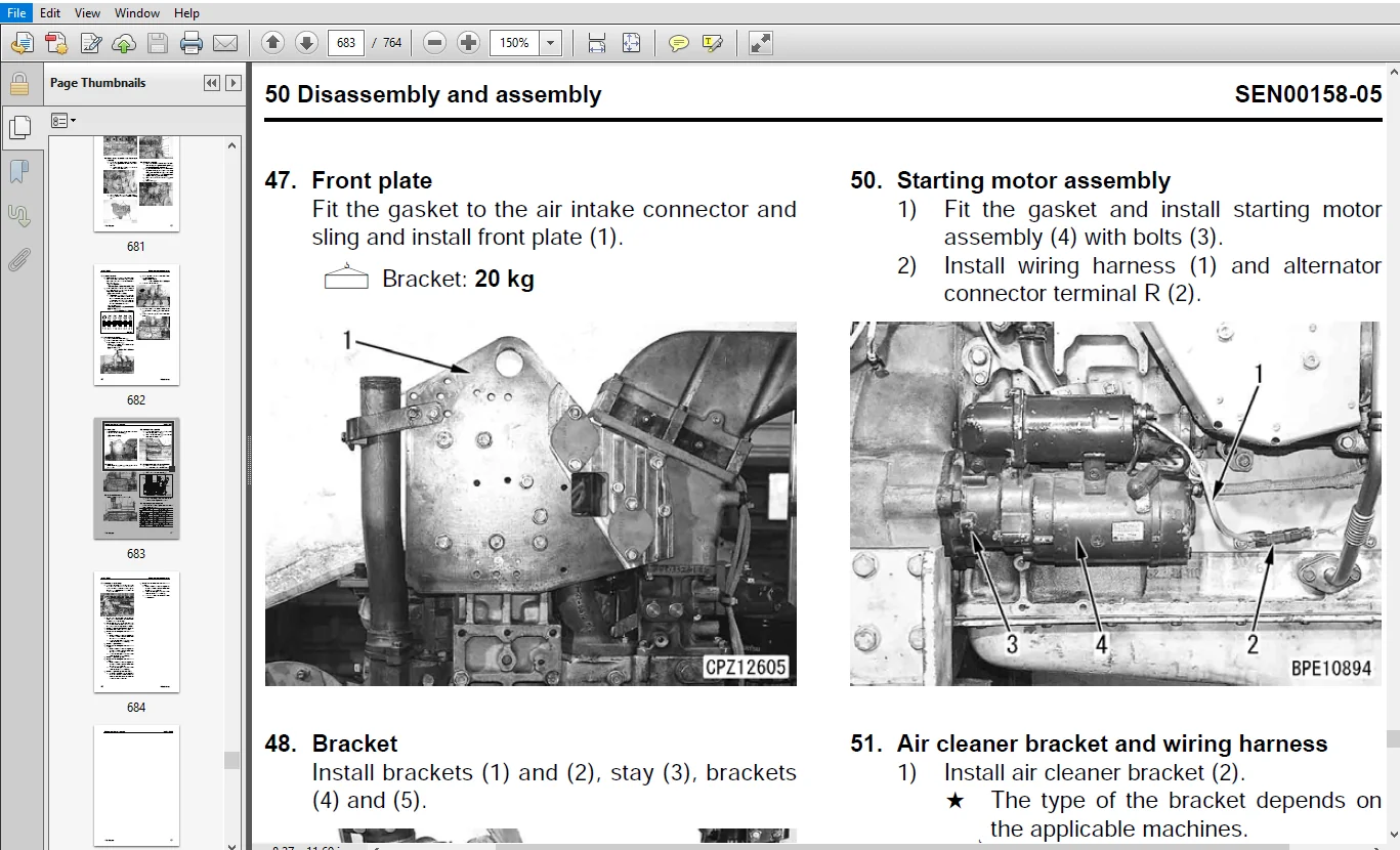
50. Disassembly and assembly
This section explains the special tools and procedures for removing, installing, disassembling, and assembling each component, as well as precautions for them. In addition, tightening torque and quantity and weight of coating material, oil, grease, and coolant necessary for the work are also explained.
90. Diagrams and drawings (chassis volume)/Repair and replacement of parts (engine volume)
Chassis volume
This section gives hydraulic circuit diagrams and electrical circuit diagrams.
Engine volume
This section explains the method of reproducing, repairing, and replacing parts.
TABLE OF CONTENTS:
KOMATSU 140E-5 SERIES SERVICE REPAIR MANUAL (SEN00074-16)
COVER
...........................................................................................  1
00 Index and foreword............................................................................  0
	Index........................................................................................  3
		Composition of shop manual...............................................................  4
		Table of contents........................................................................  5
	Foreword and general information............................................................. 13
		Safety notice............................................................................ 14
		How to read the shop manual.............................................................. 19
		Explanation of terms for maintenance standard............................................ 21
		Handling of electric equipment and hydraulic component................................... 23
		Handling of connectors newly used for engines............................................ 32
		How to read electric wire code........................................................... 35
		Precautions when carrying out operation.................................................. 38
		Method of disassembling and connecting push-pull type coupler............................ 41
		Standard tightening torque table......................................................... 44
		Conversion table......................................................................... 48
01 Specification.................................................................................  0
	Specification and technical data............................................................. 55
		Outline.................................................................................. 56
		Specifications........................................................................... 60
		General view............................................................................. 78
		Weight table.............................................................................115
		Engine performance curves................................................................119
10 Structure, function and maintenance standard..................................................  0
	Structure, function and maintenance standard, Part 1.........................................129
		Air intake and exhaust unit..............................................................131
		Air cleaner..............................................................................133
		Turbocharger.............................................................................136
		Aftercooler..............................................................................147
		Muffler..................................................................................148
		EGR system...............................................................................153
		Cylinder head............................................................................160
		Cylinder block...........................................................................164
		Cylinder liner...........................................................................167
		Main moving parts........................................................................168
		Crankshaft...............................................................................170
		Camshaft.................................................................................171
		Cam follower and push rod................................................................172
		Piston, piston ring and piston pin.......................................................174
		Connecting rod...........................................................................176
		Flywheel and flywheel housing............................................................177
		Vibration damper.........................................................................180
		Timing gear..............................................................................182
		Valve system.............................................................................186
		Valve and valve guide....................................................................188
		Rocker arm and shaft.....................................................................190
		Crosshead and guide......................................................................191
	Structure, function and maintenance standard, Part 2.........................................193
		Lubrication system.......................................................................196
			Lubrication system diagram...........................................................196
			Oil pump.............................................................................200
			EGR oil pump.........................................................................201
			Oil filter...........................................................................202
			Oil cooler...........................................................................204
		Fuel system..............................................................................206
			CRI system diagram...................................................................206
			Outline of CRI system................................................................208
			Fuel piping..........................................................................230
			Fuel cooler..........................................................................234
			Fuel filter..........................................................................235
			Priming pump.........................................................................238
			Electric priming pump................................................................239
			Engine controller cooler.............................................................240
		Cooling system...........................................................................241
			Cooling system diagram...............................................................241
			Water pump...........................................................................246
			Thermostat...........................................................................249
			Corrosion resistor...................................................................250
			Cooling fan drive....................................................................252
		Accessories..............................................................................255
			Front PTO............................................................................255
		Electrical equipment.....................................................................257
			Alternator...........................................................................257
			Starting motor.......................................................................268
			Starting aid.........................................................................270
			Engine controller....................................................................271
20 Standard value table..........................................................................  0
	Standard service value table.................................................................273
		Standard service value table for testing, adjusting, and troubleshooting.................274
		Running-in standard and performance test standard........................................291
30 Testing and adjusting.........................................................................  0
	Testing and adjusting........................................................................309
		Testing and adjusting (with EGR).........................................................311
			Testing and adjusting tools list.....................................................311
			Sketches of special tools............................................................313
			Testing air boost pressure...........................................................314
			Testing exhaust temperature..........................................................315
			Adjusting valve clearance............................................................316
			Testing compression pressure.........................................................317
			Testing blow-by pressure.............................................................319
			Testing engine oil pressure..........................................................320
			Testing EGR valve and bypass valve drive oil pressure................................321
			Handling fuel system parts...........................................................322
			Releasing residual pressure in fuel system...........................................322
			Testing fuel pressure................................................................323
			Reduced cylinder mode operation......................................................324
			No-injection cranking................................................................324
			Testing fuel return rate and leakage.................................................325
			Bleeding air from fuel circuit.......................................................328
			Testing fuel system for leakage......................................................330
			Testing and adjusting alternator belt tension........................................331
			Testing and adjusting fan belt tension...............................................332
			Handling controller high-voltage circuit.............................................333
		Testing and adjusting (EGR-less).........................................................334
			Testing and adjusting tools list.....................................................334
			Sketches of special tools............................................................336
			Testing air boost pressure...........................................................337
			Testing exhaust temperature..........................................................338
			Adjusting valve clearance............................................................339
			Testing compression pressure.........................................................340
			Testing blow-by pressure.............................................................342
			Testing engine oil pressure..........................................................343
			Handling fuel system parts...........................................................344
			Releasing residual pressure in fuel system...........................................344
			Testing fuel pressure................................................................345
			Reduced cylinder mode operation......................................................346
			No-injection cranking................................................................346
			Testing fuel return rate and leakage.................................................347
			Bleeding air from fuel circuit.......................................................350
			Testing fuel system for leakage......................................................352
			Testing and adjusting alternator belt tension........................................353
			Testing and adjusting fan belt tension...............................................354
			Handling controller high-voltage circuit.............................................355
40 Troubleshooting...............................................................................  0
	General information on troubleshooting.......................................................357
		Points to remember when troubleshooting..................................................358
		Method of displaying trouble diagnosis lamps (Method of displaying error code)...........359
		Error codes and failure codes list.......................................................361
		Information in troubleshooting table.....................................................366
		Connection table for connector pin numbers...............................................368
		T- branch box and T- branch adapter table................................................404
	Troubleshooting of mechanical system (S-mode)................................................409
		Troubleshooting of mechanical system (S-mode)............................................412
			Method of using troubleshooting charts...............................................412
			S-1 Starting performance is poor.....................................................416
			S-2 Engine does not start............................................................418
			S-3 Engine does not pick up smoothly.................................................422
			S-4 Engine stops during operations...................................................423
			S-5 Engine does not rotate smoothly..................................................424
			S-6 Engine lacks output (or lacks power).............................................425
			S-7 Exhaust smoke is black (incomplete combustion)...................................426
			S-8 Oil consumption is excessive (or exhaust smoke is blue)..........................428
			S-9 Oil becomes contaminated quickly.................................................429
			S-10 Fuel consumption is excessive...................................................430
			S-11 Oil is in coolant (or coolant spurts back or coolant level goes down)...........431
			S-12 Oil pressure drops..............................................................432
			S-13 Oil level rises (Entry of coolant/fuel).........................................433
			S-14 Coolant temperature becomes too high (overheating)..............................435
			S-15 Abnormal noise is made..........................................................436
			S-16 Vibration is excessive..........................................................437
	Troubleshooting of electrical system (E-mode), Part 1........................................439
		Troubleshooting of electrical system (E-mode), Part 1....................................441
			Troubleshooting method for disconnecting wiring harness of pressure sensor system....441
			E-1 Code [111/CA111] Engine Controller Internal Failure..............................444
			E-2 Code [115/CA115] Eng. Ne and Bkup Speed Sensor Error.............................445
			E-3 Code [122/CA122] Charge (boost) Air Press Sensor High Error......................446
			E-4 Code [123/CA123] Charge (boost) Air Press Sensor Low Error.......................450
			E-5 Code [131/CA131] Throttle Sensor High Error......................................454
			E-6 Code [132/CA132] Throttle Sensor Low Error.......................................458
			E-7 Code [135/CA135] Oil Press. Sensor High Error....................................460
			E-8 Code [141/CA141] Oil Press. Sensor Low Error.....................................462
			E-9 Code [144/CA144] Coolant Temp. Sensor High Error.................................464
			E-10 Code [145/CA145] Coolant Temp. Sensor Low Error.................................466
			E-11 Code [153/CA153] Charge (boost) Air Temp. Sensor High Error.....................468
			E-12 Code [154/CA154] Charge (boost) Air Temp. Sensor Low Error......................470
			E-13 Code [187/CA187] Sensor Sup. 2 Volt. Low Error..................................472
			E-14 Code [221/CA221] Ambient Air Press. Sensor High Error...........................476
			E-15 Code [222/CA222] Ambient Air Press. Sensor Low Error............................478
			E-16 Code [227/CA227] Sensor Sup. 2 Volt. High Error.................................480
			E-17 Code [234/CA234] Eng. Overspeed.................................................480
			E-18 Code [238/CA238] Ne Speed Sensor Sup. Volt. Error...............................482
			E-19 Code [263/CA263] Fuel Temp. Sensor High Error...................................484
			E-20 Code [265/CA265] Fuel Temp. Sensor Low Error....................................486
			E-21 Code [271/CA271] PCV1 Short Error...............................................488
			E-22 Code [272/CA272] PCV1 Open Error................................................490
			E-23 Code [273/CA273] PCV2 Short Error...............................................492
			E-24 Code [274/CA274] PCV2 Open Error................................................494
			E-25 Code [322/CA322] Injector #1 System Open/Short Error............................496
			E-26 Code [323/CA323] Injector #5 System Open/Short Error............................498
			E-27 Code [324/CA324] Injector #3 System Open/Short Error............................500
			E-28 Code [325/CA325] Injector #6 System Open/Short Error............................502
			E-29 Code [331/CA331] Injector #2 System Open/Short Error............................504
			E-30 Code [332/CA332] Injector #4 System Open/Short Error............................506
			E-31 Code [342/CA342] Engine Controller Data Matching Error..........................508
			E-32 Code [351/CA351] INJ. Drive Circuit Error.......................................510
			E-33 Code [352/CA352] Sensor Sup. 1 Volt. Low Error..................................512
			E-34 Code [386/CA386] Sensor Sup. 1 Volt. High Error.................................513
			E-35 Code [431/CA431] Idle Validation Switch Error...................................516
			E-36 Code [432/CA432] Idle Validation Process Error..................................518
			E-37 Code [441/CA441] Supply Voltage Low Error.......................................519
			E-38 Code [442/CA442] Supply Voltage High Error......................................519
	Troubleshooting of electrical system (E-mode), Part 2........................................521
		Troubleshooting of electrical system (E-mode), Part 2....................................523
			E-39 Code [449/CA449] Rail Press. High Error 2.......................................523
			E-40 Code [451/CA451] Rail Press. Sensor High Error..................................524
			E-41 Code [452/CA452] Rail Press. Sensor Low Error...................................527
			E-42 Code [553/CA553] Rail Press. High Error 1.......................................528
			E-43 Code [554/CA554] Rail Press Sensor In Range Error...............................529
			E-44 Code [559/CA559] No-pressure Feed By Supply pump 1..............................530
			E-45 Code [689/CA689] Eng. Ne Speed Sensor Error.....................................534
			E-46 Code [731/CA731] Eng. Bkup Speed Sensor Phase Error.............................536
			E-47 Code [757/CA757] All Engine Controller Data Lost Error..........................536
			E-48 Code [778/CA778] Eng. Bkup Speed Sensor Error...................................538
			E-49 Code [1228/CA1228] EGR Valve Servo Error 1......................................541
			E-50 Code [1625/CA1625] EGR Valve Servo Error 2......................................542
			E-51 Code [1626/CA1626] Bypass Valve Solenoid Drive Short Circuit Error..............543
			E-52 Code [1627/CA1627] Bypass Valve Solenoid Drive Open Error.......................545
			E-53 Code [1628/CA1628] Bypass Valve Servo Error 1...................................546
			E-54 Code [1629/CA1629] Bypass Valve Servo Error 2...................................547
			E-55 Code [1631/CA1631] Bypass Valve Lift Sensor High Error..........................548
			E-56 Code [1632/CA1632] Bypass Valve Lift Sensor Low Error...........................550
			E-57 Code [1633/CA1633] KOMNET Error.................................................550
			E-58 Code [1642/CA1642] EGR Inlet Press Sensor Low Error.............................551
			E-59 Code [1653/CA1653] EGR Inlet Press Sensor High Error............................552
			E-60 Code [2185/CA2185] Throttle Sens. Sup. Volt. High Error.........................554
			E-61 Code [2186/CA2186] Throttle Sens. Sup. Volt. Low Error..........................558
			E-62 Code [2249/CA2249] No-pressure Feed By Supply pump 2............................558
			E-63 Code [2271/CA2271] EGR Valve Lift Sensor High Error.............................559
			E-64 Code [2272/CA2272] EGR Valve Lift Sensor Low Error..............................561
			E-65 Code [2351/CA2351] EGR Valve Solenoid Drive Short Error.........................562
			E-66 Code [2352/CA2352] EGR Valve Solenoid Drive Open Error..........................564
			E-67 Code [2555/CA2555] Intake Air Heater Relay Open Error...........................565
			E-68 Code [2556/CA2556] Intake Air Heater Relay Short Error..........................566
			E-69 Code [(143)/B@BAZG] Eng. Oil Press Low Torque Derate............................568
			E-70 Code [(146)/B@BCNS] Eng. Overheat...............................................568
			E-71 Code [(415)/B@BAZG] Eng. Oil Press. Low Speed Derate............................569
50 Disassembly and assembly......................................................................  0
	General information on disassembly and assembly..............................................571
		General information on disassembly and assembly..........................................572
			How to read this manual..............................................................572
			Coating materials list...............................................................574
			Special tools list...................................................................577
			Sketches of special tools............................................................578
	Disassembly and assembly, Part 1 (with EGR)..................................................583
		Disassembly and assembly, Part 1 (with EGR)..............................................584
			General disassembly of engine........................................................584
			General assembly of engine...........................................................602
	Disassembly and assembly, Part 2 (EGR-less)..................................................637
		Disassembly and assembly, Part 2 (EGR-less)..............................................638
			General disassembly of engine........................................................638
			General assembly of engine...........................................................654
	Disassembly and assembly, Part 3.............................................................687
		Disassembly and assembly, Part 3.........................................................688
			Removal and installation of fuel supply pump unit (with EGR).........................688
			Removal and installation of fuel supply pump unit (EGR-less).........................690
			Replacement of oil seal of engine mounted on machine.................................693
90 Repair and replacement of parts...............................................................  0
	Information related to repair and replacement................................................699
		Flowchart................................................................................700
		Special tool table.......................................................................702
		Special tool sketch......................................................................704
	Cylinder head................................................................................709
		Part names related to cylinder head......................................................710
		Testing and inspection of cylinder head..................................................711
		Pressure test of cylinder head...........................................................713
		Replacement of valve guide...............................................................713
		Replacement of valve seat insert.........................................................714
		Replacement of crosshead guide...........................................................721
		Repair of cylinder head mounting face by grinding........................................722
		Repair of valve by grinding..............................................................723
	Cylinder block...............................................................................725
		Part names related to cylinder block.....................................................727
		Testing and inspection of cylinder block.................................................728
		Method of checking main bearing metal inside diameter with alignment bar.................730
		Part names related to crankshaft.........................................................731
		Testing and inspection of crankshaft.....................................................732
		Part names related to connecting rod.....................................................733
		Testing and inspection of connecting rod.................................................734
		Replacement of flywheel ring gear........................................................735
		Replacement of crankshaft gear...........................................................736
		Replacement of camshaft gear.............................................................737
		Replacement of main bearing metal cap....................................................738
		Replacement of connecting rod small end bushing..........................................740
		Replacement of cam bushing...............................................................741
		Repair of cylinder block top by grinding.................................................743
		Repair of counterbore by grinding........................................................744
		Check and identification after repair by grinding........................................746
		Gasket sealant application procedure.....................................................747
		Repair standard for cylinder liner O-ring................................................749
		Replacement of engine rear seal..........................................................750
		Replacement of wear sleeve (when sleeve is installed)....................................754
		Repair of crankshaft by grinding.........................................................755
		Improvement of surface roughness of crankshaft journal...................................760
PLEASE NOTE:
⦁ This is not a physical manual but a digital manual – meaning no physical copy will be couriered to you. The manual can be yours in the next 2 mins as once you make the payment, you will be directed to the download page IMMEDIATELY.
⦁ This is the same manual used by the dealers inorder to diagnose your vehicle of its faults.
⦁ Require some other service manual or have any queries: please WRITE to us at [email protected]


Marco Jaxx –