
Komatsu 4D92E 4D94LE 4D98E Diesel Engine Shop Manual – 4D94E-BE3 PDF for FD Series Forklifts
Original price was: $55.95.$34.95Current price is: $34.95.
Complete Komatsu shop manual (4D94E-BE3) for the 4D92E, 4D94LE and 4D98E water-cooled diesel engines fitted to FD10 through FD35A forklifts. Engine body, fuel injection pump and governor, lubrication, cooling, starting motor, alternator, troubleshooting, adjustment values and service standards, all in one PDF.
Description
Komatsu 4D92E / 4D94LE / 4D98E Diesel Engine Shop Manual – 4D94E-BE3
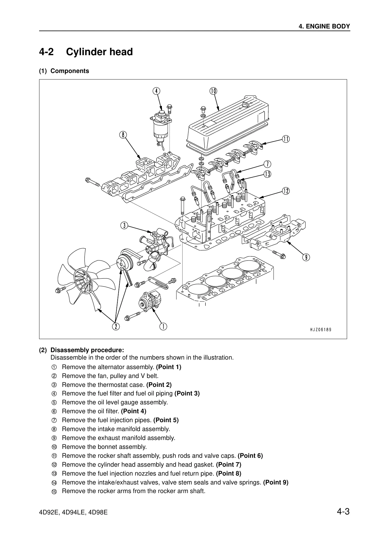
This is the Komatsu shop manual released under document code 4D94E-BE3 for the 4D92E, 4D94LE and 4D98E water-cooled diesel engines used in Komatsu forklift trucks. It is written for the technician who has to pull, strip, measure, adjust and rebuild these engines — not a brochure and not a condensed owner’s booklet. Every chapter works from exploded views, sectional drawings and system diagrams, with the removal/installation sequence numbered directly on the illustration and the critical points called out as they come up. If you service FD-series forklifts powered by these three engines, this is the document you keep open on the bench.
File Details
- Manual type: Shop Manual
- Document code: 4D94E-BE3
- Brand / publisher: Komatsu Forklift
- Engines covered: 4D92E, 4D94LE, 4D98E
- Language: English
- Page count: 159
- File format: PDF
Applicable Machines and Serial Numbers
- 4D92E — FD10/15/18-20, serial 650001 and up
- 4D94LE — FD20/25/30-16 and FD20N/25N/30N-16, serial 700001 and up
- 4D98E — FD20H/25H/30H/35A-16, serial 700001 and up
Chapters Covered
- 1. General
- 2. Troubleshooting
- 3. Inspection and Adjustment
- 4. Engine Body
- 5. Lubrication System
- 6. Cooling System
- 7. Fuel Injection Pump, Governor
- 8. Starting Motor
- 9. Alternator
- 10. Special Service Tools
- 11. Service Standards
General
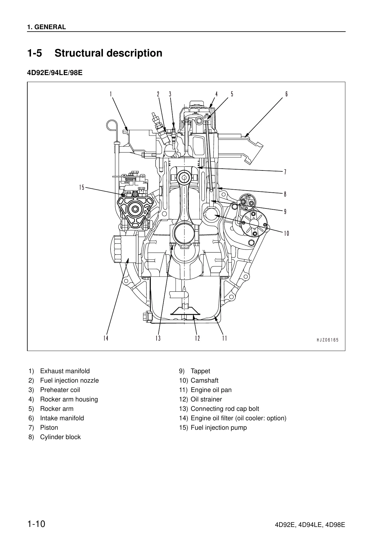
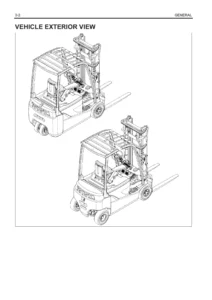
Opens with the full engine specification table comparing all three engines side by side — cylinder bore and stroke, displacement, rated output and speed, injection timing and pressure, firing order, rotation direction, fuel and lubricant requirements, battery capacity, oil and coolant capacities, external dimensions and dry weight. Also covers the recommended fuel oil, lubricating oil and cooling water, engine performance curves for the 4D92E and 4D94LE, external engine views, a structural description keyed to numbered cutaway drawings, how to read the manual, safety precautions for service work, and the standard tightening torque table for hexagon bolts, nuts, PT plugs and pipe joint bolts. Use this chapter first — it tells you what you are working on and how tight everything goes back.
Troubleshooting
A quick-reference fault table that crosses symptoms against causes across the whole engine: starting failure, engine starts but stops, insufficient output, poor exhaust colour, abnormal noise, hunting, poor return to low speed, and excessive fuel consumption. The matrix splits the causes into engine system, lubricating system, fuel system, air/exhaust gas system, cooling water system and electrical system, with a corrective action column pointing to the chapter that fixes it. Compression pressure troubleshooting follows: how to measure it, the standard and limit values (2.84–3.04 MPa / 29–31 kgf/cm² standard, 2.35 MPa / 24 kgf/cm² limit at 250 rpm), allowable dispersion between cylinders, the compression-vs-engine-speed reference graph, and a measured-value table telling you whether the loss is air cleaner, valve clearance, valve timing, head gasket, valve seat or piston/ring/cylinder.
Inspection and Adjustment
The routine service chapter. Coolant system and radiator leak testing with a cap tester, radiator cap opening check, fan belt tension inspection and adjustment (10–15 mm deflection on a used belt, 7–9 mm on a new one at 98 N / 10 kgf), cold valve clearance adjustment to 0.15–0.25 mm, fuel injection nozzle testing for injection pressure and spray pattern, fuel injection timing inspection and adjustment using the dial gauge plunger lift method, no-load maximum and minimum engine speed adjustment, thermostat and thermal switch inspection, oil pressure switch testing, battery inspection with a tester or hydrometer including the temperature correction formula, the post-repair adjusting run sequence, long-term storage procedure, and the periodic maintenance schedule with the daily / 50 hour / 250 hour / 500 hour / 1000 hour / 2000 hour intervals.
Engine Body
The largest section. Cylinder head removal and refitting including the two-step head bolt loosening and tightening orders at 49–58.8 Nm then 102.9–112.7 Nm, valve, valve guide, valve spring, rocker arm and push rod inspection with all standard and limit dimensions, valve seat correction by cutter or grinder with the intake 120° / exhaust 90° seat angles and 40° / 150° correction angles, valve guide and valve stem seal replacement. Gear train and camshaft: gear backlash values, camshaft end play, cam height, camshaft journal and bushing clearances, camshaft and idle gear removal, PTO gear, flywheel and oil seal replacement. Cylinder block: piston with connecting rod removal, main bearing cap and crankshaft removal, crankshaft end play and thrust metal, piston ring fitment with the 120° joint stagger, cylinder bore measurement positions and reboring/honing procedure, piston pin bushing replacement, and the oversize piston and head gasket part-code tables.
Lubrication System
Lubrication circuit diagram showing the crankshaft and camshaft bearings, the feed to the cylinder head for rocker arm lubrication and the feed to the gear case. Trochoid pump components, disassembly and reassembly, servicing points for the pressure regulator valve and outer rotor alignment, and inspection of the outer rotor oil clearance, side clearance, rotor shaft and bearing clearance.
Cooling System
Cooling water circuit diagram covering the flow from the cylinder head through the water pump, bypass and radiator. Cooling water pump exploded component view, removal sequence, and the pump bearing inspection points for noise, sticking, play and water leakage. Thermostat removal and function check.
Fuel Injection Pump, Governor
Detailed coverage of the VE-type injection pump: specifications, component identification, system diagram, pump removal and installation including the drive gear match marks, the full fuel system flow from tank through sedimenter, priming pump, fuel filter, feed pump, regulating valve, plunger and barrel, magnet valve and overflow valve to the nozzle. Structure and operation of the pump and plunger — suction stroke, injection stroke, end of injection and pressure equalizing stroke — the reverse revolution prevention mechanism, fuel injection rate control, delivery valve and damping valve operation. The all-speed governor section works through the start, idle, full-load maximum speed and no-load maximum speed control conditions, plus the full load position adjustment mechanism.
Starting Motor and Alternator
Starting motor: specifications, components, a diagnostic flow chart for starting failure, complete disassembly and assembly procedure, armature, field coil, brush, brush holder, magnetic switch and pinion clutch inspection with service standards, grease application points, pinion projection length adjustment (0.3–1.5 mm) and a no-load characteristic test circuit. Alternator: specifications, sectional view, troubleshooting chart, disassembly and assembly, diode, rotor, stator, brush and IC regulator inspection, service standards and the full performance test circuit for adjustment voltage, operating speed and output current.
Special Service Tools and Service Standards
The special tools list with dimensions and illustration references for the valve guide extractor and inserter, connecting rod bushing replacer, valve spring compressor, valve stem seal inserter, filter wrench, camshaft bushing tool and Flex-Hone — plus the measuring instruments you need for the job. The service standards chapter then gathers everything into one place: engine tuning values, cylinder head, valve and valve guide, valve spring, rocker arm and shaft, push rod, camshaft, idle gear, cylinder block, crankshaft, thrust bearing, piston and ring, connecting rod and tappet limits — and a tightening torque table for the main parts of the engine, split by assembly, with the important bolts and lubricated bolts marked.
Why This Komatsu Diesel Engine Shop Manual Belongs on Your Bench
A forklift engine does not fail politely. A 4D92E or 4D94LE that will not start, hunts at idle, smokes white or black, loses compression or blows a head gasket needs a diagnosis, not a guess — and the difference between a two-hour fix and a two-week comeback is having the correct measurement, the correct clearance and the correct tightening sequence in front of you. This shop manual gives you the compression pressure figures, the valve clearance, the injection timing plunger lift, the gear backlash, the bearing oil clearances and the two-stage head bolt torques for all three engines, along with the exploded views that show you exactly how a subassembly comes apart before you put a puller on it.
With the 4D94E-BE3 shop manual you can strip and rebuild a cylinder head, replace valve guides and lap seats, pull and refit pistons and connecting rods, service the crankshaft and main bearings, overhaul the trochoid lubrication pump, pull the cooling water pump and thermostat, remove and refit the VE injection pump with the correct drive gear timing, service the starting motor and alternator down to brush and diode level, and run the fault-finding tables when the symptom does not point straight at the cause. Whether you run a small forklift fleet, work in a workshop servicing Komatsu FD trucks, or are rebuilding one of these engines on your own, the numbers here are the ones the engine was built to.
IMAGES PREVIEW
Delivery is instant. The manual is supplied as a PDF that downloads immediately after payment — no shipping, no waiting, no import charges. Open it on a laptop in the workshop, a tablet next to the machine or a phone in the yard, print the pages you need for the job and throw them away when they get oily. Every diagram, table and procedure is in the same file.
Reviews
There are no reviews yet.