Trusted Business
Verified & Licensed
Virus Free Files
100% Safe Downloads
Secure Payment
SSL Protected
Instant Delivery
Available Immediately
Sale!


KOMATSU 6D170-1 SERIES DIESEL ENGINE SERVICE REPAIR MANUAL (SEBE6161A16) KOMATSU 6D170 1 – PDF DOWNLOAD
Original price was: $84.95.$26.95Current price is: $26.95.
- KOMATSU 6D170-1 SERIES DIESEL ENGINE SERVICE REPAIR MANUAL
- PUBLICATION NUMBER:SEBE6161A16
Instant PDF Download
Available immediately
Save to Your Device
Download & keep forever
Antivirus Scanned
100% virus-free
Trusted Worldwide
175,000+ customers
Description
KOMATSU 6D170-1 SERIES DIESEL ENGINE SERVICE REPAIR MANUAL (SEBE6161A16) KOMATSU 6D170 1
KOMATSU 6D170-1 SERIES DIESEL ENGINE SERVICE REPAIR MANUAL (SEBE6161A16) KOMATSU 6D170 1 – PDF DOWNLOAD:
IMAGE PREVIEW:
DESCRIPTION:
KOMATSU 6D170-1 SERIES DIESEL ENGINE SERVICE REPAIR MANUAL (SEBE6161A16) KOMATSU 6D170 1
- This shop manual has been prepared as an aid to improve the quality of repairs by giving the serviceman an accurate understanding of the product and by showing him the correct way to perform repairs and make judgements. Make sure you understand the contents of this manual and use it to full effect at every opportunity.
- This shop manual mainly contains the necessary technical information for operations performed in a service workshop. For ease of understanding, the manual is divided into the following chapters; these chapters are further divided into the each main group of components.
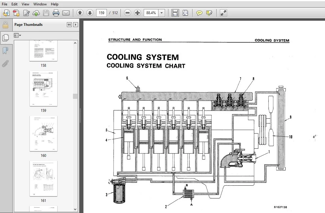
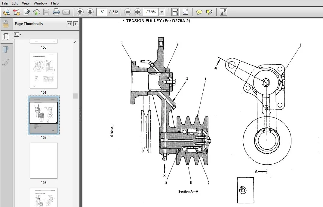
- STRUCTURE AND FUNCTION
This section explains the structure and function of each component. It serves not only to give an understanding of the structure, but also serves as reference material for troubleshooting. - TESTING AND ADJUSTING
This section explains checks to be made before and after performing repairs, as well as adjustments to be made at completion of the checks and repairs. Troubleshooting charts correlating “Problems” to “Causes” are also included in this section. - DISASSEMBLY AND ASSEMBLY
This section explains the order to be followed when removing, installing, disassembling or assembling each component, as well as precautions to be taken for these operations. - MAINTENANCE STANDARD
This section gives the judgement standards when inspecting disassembled parts.
TABLE OF CONTENTS:
KOMATSU 6D170-1 SERIES DIESEL ENGINE SERVICE REPAIR MANUAL (SEBE6161A16) KOMATSU 6D170 1
MAIN MENU.....................................................................................  0
COVER.........................................................................................  1
CONTENTS......................................................................................  2
SAFETY........................................................................................  7
	SAFETY NOTICE.............................................................................  7
01 GENERAL.................................................................................... 25
	GENERAL VIEW.............................................................................. 26
	SPECIFICATIONS............................................................................ 28
	GENERAL ASSEMBLY DRAWING.................................................................. 45
	WEIGHT TABLE.............................................................................. 57
	ENGINE PERFORMANCE CURVE.................................................................. 58
11 STRUCTURE AND FUNCTION..................................................................... 94
	GENERAL STRUCTURE......................................................................... 95
	INTAKE AND EXHAUST SYSTEM................................................................. 97
		INTAKE AND EXHAUST SYSTEM............................................................. 97
		TURBOCHARGER..........................................................................106
		AFTER-COOLER..........................................................................110
	ENGINE BODY...............................................................................111
		CYLINDER HEAD.........................................................................111
		VALVE SYSTEM..........................................................................113
		CYLINDER BLOCK........................................................................115
		MAIN CIRCULATION PART.................................................................117
		TIMING GEAR...........................................................................121
		FLYWHEEL AND FLYWHEEL HOUSING.........................................................123
	LUBRICATION SYSTEM........................................................................124
		LUBRICATION SYSTEM CHART..............................................................124
		OIL PUMP..............................................................................125
		OIL FILTER AND SAFETY VALVE...........................................................126
		OIL COOLER............................................................................127
		OIL PUMP RELIEF VALVE.................................................................130
		OIL COOLER BY-PASS VALVE..............................................................130
		PISTON COOLING VALVE..................................................................131
		MECHANICAL PUMP.......................................................................132
	FUEL SYSTEM...............................................................................133
		FUEL SYSTEM CHART.....................................................................133
		FUEL INJECTION PUMP...................................................................135
		FUEL INJECTION NOZZLE.................................................................139
		FUEL INJECTION PUMP DRIVE.............................................................140
		FUEL FILTER...........................................................................143
		FUEL CUT SOLENOID.....................................................................144
		ENGINE STOP MOTOR.....................................................................146
		STARTING AID..........................................................................152
		OUTLINE OF ELECTRONICAL GOVERNOR SYSTEM (with electronical governor made by ZEXEL)....153
	COOLING SYSTEM............................................................................159
		COOLING SYSTEM CHART..................................................................159
		WATER PUMP............................................................................160
		FAN DRIVE AND TENSION PULLEY..........................................................161
		CORROSION RESISTOR....................................................................167
		THERMOSTAT............................................................................168
	ACCESSORY.................................................................................169
		AIR COMPRESSOR MOUNTING...............................................................169
		AIR COMPRESSOR........................................................................172
	ELECTRICAL SYSTEM.........................................................................173
		ALTERNATOR............................................................................173
		STARTING MOTOR........................................................................178
		WIRING DIAGRAM........................................................................182
12 TESTING AND ADJUSTING......................................................................184
	ENGINE BODY...............................................................................190
		ADJUSTING VALVE CLEARANCE.............................................................190
		MEASURING COMPRESSION PRESSURE........................................................191
	FUEL SYSTEM...............................................................................192
		TESTING AND ADJUSTlNG FUEL INJECTION TMING............................................192
		ADJUSTING FUEL CUT SOLENOID...........................................................194
		PROCEDURE FOR ADJUSTING ENGINE STOP MOTOR CABLE.......................................198
		ADJUSTING FUEL (VALVE CRACKING INJECTION PRESSURE PRESSURE)...........................200
		METHOD FOR INSTALLING (ADJUSTMENT) OF ENGINE SPEED SENSOR.............................201
		CALIBRATION DATA......................................................................204
	COOLING SYSTEM............................................................................270
		FAN BELT TENSION......................................................................270
		REPLACING FAN BELT AND AQJUSTING AUTO TENSIONER.......................................271
	PERFORMANCE TEST..........................................................................272
		RUN-IN STANDARD.......................................................................272
		PERFORMANCE TEST CRITERIA.............................................................283
		TESTING AND ADJUSTING TOOL LIST.......................................................308
		TESTING AND ADJUSTING DATE............................................................309
		FAN BELT TENSION......................................................................329
	TROUBLESHOOTING...........................................................................332
		POINTS TO REMEMBER WHEN TROUBLESHOOTING...............................................334
		METHOD OF USING TROUBLESHOOTING CHART.................................................335
		S-1 Starting performance is poor (Starting always takes time).........................339
		S-2 Engine does not start.............................................................340
			1) Engine does not turn...........................................................340
			2) Engine turns but no exhaust gas comes out (Fuel is not being injected).........341
			3) Exhaust gas comes out but engine does not start (Fuel is being injected).......342
		S-3 Engine does not pick up smoothly (Follow-up is poor)..............................343
		S-4 Engine stops during operations....................................................344
		S-5 Engine does not rotate smoothly (hunting).........................................345
		S-6 Engine lacks output (no power)....................................................346
		S-7 Exhaust gas is black (incomplete combustion)......................................347
		S-8 Oil consumption is excessive (or exhaust gas is blue).............................348
		S-9 Oil becomes contaminated quickly..................................................349
		S-10 Fuel consumption is excessive....................................................350
		S-11 Oil is in cooling water, or water spurts back, or water level goes down..........351
		S-12 Oil pressure lamp lights up (drop in oil pressure)...............................352
		S-13 Oil level rises..................................................................353
		S-14 Water temperature becomes too high (overheating).................................354
		S-15 Abnormal noise is made...........................................................355
		S-16 Vibration is excessive...........................................................356
13 DISASSEMBLY AND ASSEMBLY...................................................................374
	DISASSEMBLY...............................................................................375
		WASHING...............................................................................392
		WASHING CYLINDER BLOCK................................................................392
		WASHING CRANKSHAFT....................................................................393
		MEASURING PARTS.......................................................................394
	ASSEMBLY..................................................................................400
14 MAINTENANCE STANDARD.......................................................................434
	INTAKE AND EXHAUST SYSTEM.................................................................435
		TURBOCHARGER..........................................................................435
	ENGINE BODY...............................................................................440
		CYLINDER HEAD.........................................................................440
		VALVES AND VALVE GUIDE................................................................441
		CROSSHEAD AND CROSSHEAD GUIDE.........................................................442
		PUSH ROD AND CAM FOLLOWER.............................................................443
		CYLINDER BLOCK........................................................................444
		CYLINDER LINER........................................................................446
		CRANKSHAFT............................................................................447
		CAMSHAFT..............................................................................448
		TIMING GEAR...........................................................................449
		PISTON, PISTON RING AND PISTON PIN....................................................451
		CONNECTING ROD........................................................................453
	LUBRICATION SYSTEM........................................................................454
		OIL PUMP..............................................................................454
		OIL PUMP RELIEF VALVE, PISTON COOLING VALVE AND OIL COOLER BY-PASS VALVE..............455
	COOLING SYSTEM............................................................................456
		WATER PUMP............................................................................456
	ACCESSORY.................................................................................458
		AIR COMPRESSOR........................................................................458
15 REPAIR AND REPLACEMENT OF PARTS............................................................461
	TABLE OF SPECIAL TOOLS....................................................................462
	CYLINDER HEAD.............................................................................464
	TESTING AND INSPECTING....................................................................465
	REPAIRING MOUNTING FACE OF CYLINDER HEAD BY GRINDING......................................467
	REPLACING VALVE SEAT INSERTS..............................................................468
	REPLACING NOZZLE HOLDER SLEEVE............................................................474
	REPLACING VALVE GUIDE.....................................................................478
	REPLACING CROSS HEAD GUIDE................................................................479
	GRINDING THE VALVE........................................................................480
	CYLINDER BLOCK............................................................................481
	TESTING AND INSPECTING....................................................................482
	GRINDING THE TOP SURFACE OF CYLINDER BLOCK................................................484
	REPLACING MAIN METAL CAP..................................................................490
	REPLACING CAM BUSHING.....................................................................492
	CRANKSHAFT................................................................................494
	REPAIRING THE CRANKSHAFT..................................................................501
	CONNECTING ROD............................................................................506
	REPLACING CRANKSHAFT GEAR.................................................................508
	REPLACING CAMSHAFT GEAR...................................................................509
	REPLACING FLYWHEEL RING GEAR..............................................................510
PLEASE NOTE:
⦁ This is not a physical manual but a digital manual – meaning no physical copy will be couriered to you. The manual can be yours in the next 2 mins as once you make the payment, you will be directed to the download page IMMEDIATELY.
⦁ This is the same manual used by the dealers inorder to diagnose your vehicle of its faults.
⦁ Require some other service manual or have any queries: please WRITE to us at [email protected]


J Julio –