
Trusted Business
Verified & Licensed
Virus Free Files
100% Safe Downloads
Secure Payment
SSL Protected
Instant Delivery
Available Immediately
Sale!


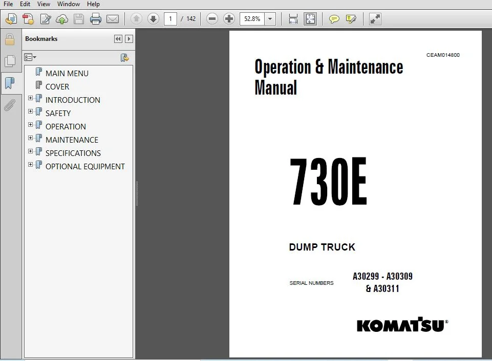
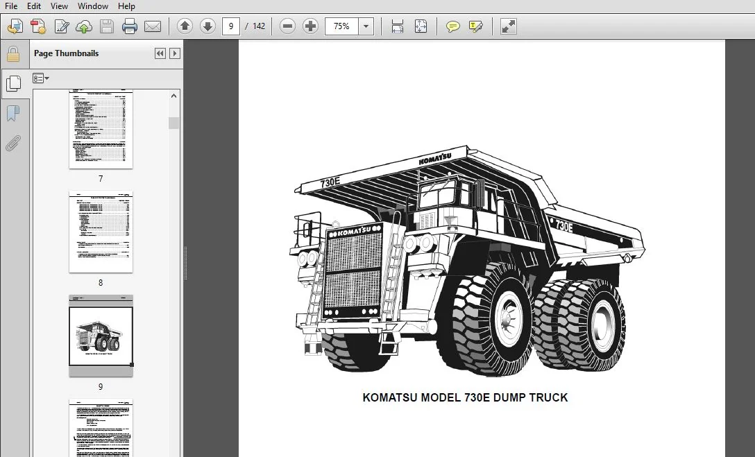
KOMATSU 730E DUMP TRUCK OPERATION & MAINTENANCE MANUAL (SN:A30299 – A30309 & A30311) – PDF DOWNLOAD
Original price was: $71.95.$26.95Current price is: $26.95.
- KOMATSU 730E DUMP TRUCK OPERATION & MAINTENANCE MANUAL
- SERIAL NUMBER:A30299 – A30309 & A30311
- PUBLICATION NUMBER:CEAM014800
Instant PDF Download
Available immediately
Save to Your Device
Download & keep forever
Antivirus Scanned
100% virus-free
Trusted Worldwide
175,000+ customers
Description
KOMATSU 730E DUMP TRUCK OPERATION & MAINTENANCE MANUAL (SN:A30299 – A30309 & A30311)
KOMATSU 730E DUMP TRUCK OPERATION & MAINTENANCE MANUAL (SN:A30299 – A30309 & A30311) – PDF DOWNLOAD:
IMAGE PREVIEW:
DESCRIPTION:
KOMATSU 730E DUMP TRUCK OPERATION & MAINTENANCE MANUAL (SN:A30299 – A30309 & A30311)
- This manual is written for use by the operator and/or the service technician and is designed to help these persons to become fully knowledgeable of the truck and all its systems in order to keep it operating safely and efficiently.
- All operators and maintenance personnel should read and understand the materials in this manual before operating the truck or performing maintenance and/or operational checks on the truck. All safety notices, warnings and cautions should be understood and followed when operating or accomplishing repairs on the truck.
- The first section is an Introduction to the manual and contains a Table of Contents to locate specific areas of interest. Other sections include Safety, Operation, Maintenance, Specifications, and Optional Equipment.
- The illustrations used in this manual are TYPICAL of the component shown and may not be an exact reproduction of what is found on the truck.
- A product identification plate is located on the frame in front of the right side front wheel and designates the Truck Model Number, Product Identification Number (vehicle serial number), and Maximum G.V.W. (Gross Vehicle Weight) rating.
- The KOMATSU Truck Model designation consists of three numbers and one letter (i.e. 730E).
The three numbers represent the basic truck model.
The letter “M”, when present, designates a Mechanical drive system;
The letter “E”, when present, designates an Electrical wheel motor drive system. - The Product Identification Number (vehicle serial number) contains information which will identify the original manufacturing bill of material for this unit. This complete number will be necessary for proper ordering of many service parts and/or warranty consideration.
- The Gross Vehicle Weight (GVW) is what determines the load on the drive train, frame, tires, and other components. The vehicle design and application guidelines are sensitive to the total maximum Gross Vehicle Weight (GVW) GVW is TOTAL WEIGHT: the Empty Vehicle Weight + the fuel & lubricants + the payload
TABLE OF CONTENTS:
KOMATSU 730E DUMP TRUCK OPERATION & MAINTENANCE MANUAL (SN:A30299 – A30309 & A30311)
MAIN MENU.........................................................  0
COVER.............................................................  1
INTRODUCTION......................................................  4
	FOREWORD......................................................  4
	ALERTS........................................................  1
	TABLE OF CONTENTS.............................................  6
	TRUCK MODEL ILLUSTRATION......................................  9
	ABOUT THIS MANUAL............................................. 10
	STANDARD CHARTS AND TABLES.................................... 12
SAFETY............................................................ 18
	GENERAL SAFETY................................................ 18
	PRECAUTIONS DURING OPERATION.................................. 21
		BEFORE STARTING ENGINE.................................... 21
		OPERATING MACHINE......................................... 21
		BATTERY................................................... 23
		TOWING.................................................... 24
	PRECAUTIONS FOR MAINTENANCE................................... 25
		BEFORE CARRYING OUT MAINTENANCE........................... 25
		DURING MAINTENANCE........................................ 25
		TIRES..................................................... 28
	ADDITIONAL JOB SITE RULES..................................... 29
	WHEN REPAIRS ARE NECESSARY.................................... 30
	WARNINGS AND CAUTIONS......................................... 32
OPERATION......................................................... 40
	OPERATING INSTRUCTIONS........................................ 40
		Preparing for Operation................................... 40
		Safety is Thinking Ahead.................................. 40
		At The Truck - Ground Level Walk Around Inspection........ 40
	ENGINE START-UP SAFETY PRACTICES.............................. 43
	AFTER ENGINE HAS STARTED...................................... 44
	MACHINE OPERATION SAFETY PRECAUTIONS.......................... 44
	LOADING....................................................... 45
	HAULING....................................................... 45
	PASSING....................................................... 46
	DUMPING....................................................... 46
	TOWING........................................................ 48
	SAFE PARKING PROCEDURES....................................... 48
	ENGINE SHUTDOWN PROCEDURE..................................... 48
	DELAYED ENGINE SHUTDOWN PROCEDURE............................. 49
	SUDDEN LOSS OF POWER.......................................... 49
	OPERATOR CAB AND CONTROLS..................................... 50
		STEERING WHEEL AND CONTROLS............................... 51
		SERVICE BRAKE PEDAL....................................... 52
		DYNAMIC RETARDER PEDAL.................................... 52
		THROTTLE PEDAL............................................ 52
		HEATER / AIR CONDITIONER VENTS............................ 52
		HEATER / AIR CONDITIONER COMPARTMENT AND CONTROLS......... 53
		OVER HEAD PANEL AND DISPLAYS.............................. 54
		CENTER CONSOLE............................................ 55
		OPERATOR SEAT............................................. 59
	INSTRUMENT PANEL AND INDICATOR LIGHTS......................... 60
		Control Symbols........................................... 60
	INSTRUMENT PANEL.............................................. 60
	PANEL GAUGES, INDICATORS, AND CONTROLS (Figure 3-11).......... 61
	OVERHEAD STATUS / WARNING INDICATOR LIGHT PANEL............... 66
	INDICATOR LIGHT SYMBOLS....................................... 67
		(9) HAZARD WARNING LIGHTS................................. 71
		(10) LAMP TEST SWITCH / Centry™ Diagnostic Test Switch.... 71
	CENTRY™ FUEL SYSTEM DIAGNOSTICS............................... 72
		DETERMINING "FAULT" CODES................................. 72
		EXITING THE DIAGNOSTICS MODE.............................. 73
MAINTENANCE....................................................... 74
	LUBRICATION AND SERVICE....................................... 74
		SERVICE CAPACITIES........................................ 74
		HYDRAULIC TANK SERVICE.................................... 74
		COOLANT LEVEL CHECK....................................... 75
		RADIATOR FILLING PROCEDURE................................ 75
		COOLING SYSTEM RECOMMENDATIONS............................ 75
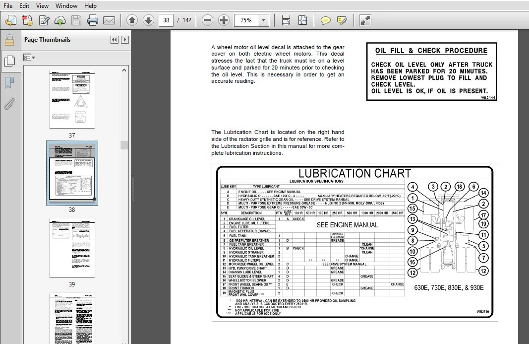
		LUBRICATION CHART......................................... 76
		10 HOUR (SHIFT) LUBRICATION AND MAINTENANCE CHECKS........ 77
		50 HOUR LUBRICATION AND MAINTENANCE CHECKS................ 79
		100 HOUR LUBRICATION AND MAINTENANCE CHECKS............... 79
		250 HOUR LUBRICATION AND MAINTENANCE CHECKS............... 80
		500 HOUR LUBRICATION AND MAINTENANCE CHECKS............... 82
		1000 HOUR LUBRICATION AND MAINTENANCE CHECKS.............. 83
		5000 HOUR LUBRICATION AND MAINTENANCE CHECKS.............. 83
	LINCOLN AUTOMATIC LUBRICATION SYSTEM.......................... 84
		GENERAL DESCRIPTION....................................... 84
		SYSTEM COMPONENTS......................................... 86
		SYSTEM OPERATION.......................................... 87
		GENERAL INSTRUCTIONS...................................... 90
			SYSTEM PRIMING........................................ 90
			LUBRICANT PUMP........................................ 90
			FILTER AND RESERVOIR.................................. 91
			INJECTORS............................................. 92
		SYSTEM CHECKOUT........................................... 93
		24 VDC SOLID STATE TIMER CHECKOUT & ADJUSTMENT............ 93
		PUMP REBUILD.............................................. 94
			DISASSEMBLY........................................... 94
			CLEANING AND INSPECTION............................... 94
			ASSEMBLY.............................................. 96
		PREVENTATIVE MAINTENANCE PROCEDURE........................100
SPECIFICATIONS....................................................102
	MAJOR COMPONENT DESCRIPTION...................................102
	SPECIFICATIONS................................................104
OPTIONAL EQUIPMENT................................................106
	PAYLOAD METER III TM..........................................106
		INDEX.....................................................106
			OPERATION SECTION.....................................108
			Introduction..........................................108
			Data Summary..........................................108
			Data Gathering........................................108
			Component Description.................................109
				System Diagram....................................109
				Suspension Pressure Sensors.......................109
				Inclinometer......................................109
				Operator Display..................................109
				Operator Switch...................................110
				Speed Input.......................................110
				Body-Up Switch....................................110
				Brake Lock Switch.................................110
				Payload Meter.....................................110
				Communications Ports..............................110
				Keyswitch Input...................................111
				Payload Meter Power...............................111
				Load Lights.......................................111
				Wiring and Termination............................112
				TCI Outputs.......................................112
			Operator's Display and Switch.........................113
				Reading the Speedometer...........................113
				Reading the Load Display..........................113
				Using the Operator ID.............................113
				Using the Load and Ton Counter....................113
					Total Ton Counter.............................113
					Total Load Counter............................114
					Clearing the Counters.........................114
				Viewing Live Sensor Data..........................114
				Other Display Messages............................114
			Payload Operation & Calculation.......................115
				Description of Haul Cycle States..................115
					Haul Cycle Description........................115
				Load Calculation..................................116
				Carry Back........................................116
				Measurement Accuracy..............................116
				Sources for Payload Error.........................116
					Payload Error.................................116
					Loading Conditions............................117
					Pressure Sensors..............................117
					Swingloads....................................117
					Speed and Distance............................117
			HAUL CYCLE DATA.......................................117
				Haul Cycle Data...................................118
				Haul Cycle Warning Flags..........................118
				Alarm Records.....................................120
				Frame Torque Data.................................120
				Sprung Weight Data................................121
				Maximum Speed Data................................121
			PC Software Overview..................................121
				PC Overview.......................................121
				System Configuration..............................121
				Installing the PLMIII Software....................121
			Downloading Data......................................122
			PLMIII System Configuration...........................123
				Starting Communications...........................123
					Displayed Payload Units.......................123
					Time Units....................................123
				Connection Menu...................................123
				Connecting to the Payload Meter...................124
				Configure the Payload Meter.......................124
					Setting the Date and Time.....................124
					Setting the Truck Type........................125
					Setting the Gauge Display Units...............125
					Setting the Frame Serial Number...............125
					Setting the Truck Number......................125
					Setting the Komatsu Distributor...............125
					Setting the Komatsu Customer..................125
				Clean Truck Tare..................................126
				Inclinometer Calibration..........................126
			Data Analysis.........................................127
				Creating a Query..................................127
					Sorting on Truck Unit Number..................127
					Sorting on Truck Type.........................127
					Sorting on Date Range.........................128
					Sorting on Time Range.........................128
				Payload Detail Screen.............................129
				Creating Reports..................................129
					Summary - one page report.....................130
					Detailed - multi-page report..................130
				Creating Graphs...................................131
				To export data in ZIP format:.....................133
				Importing Data....................................133
				Deleting Haul Cycle Records.......................133
				Viewing Alarms....................................134
				Deleting Alarm Records............................134
	RADIO, AM / FM STEREO CASSETTE................................136
PLEASE NOTE:
⦁ This is not a physical manual but a digital manual – meaning no physical copy will be couriered to you. The manual can be yours in the next 2 mins as once you make the payment, you will be directed to the download page IMMEDIATELY.
⦁ This is the same manual used by the dealers inorder to diagnose your vehicle of its faults.
⦁ Require some other service manual or have any queries: please WRITE to us at [email protected]




Gianni –
Great buy, had everything I wanted