Trusted Business
Verified & Licensed
Virus Free Files
100% Safe Downloads
Secure Payment
SSL Protected
Instant Delivery
Available Immediately
Sale!


KOMATSU 830E-1AC DUMP TRUCK FIELD ASSEMBLY MANUAL (SN:A30561 A30565) KOMATSU 830E 1AC – PDF DOWNLOAD
Original price was: $74.95.$26.95Current price is: $26.95.
- KOMATSU 830E-1AC DUMP TRUCK FIELD ASSEMBLY MANUAL
- SERIAL NUMBER:A30561 A30565
- PUBLICATION NUMBER:CEAW006700
Instant PDF Download
Available immediately
Save to Your Device
Download & keep forever
Antivirus Scanned
100% virus-free
Trusted Worldwide
175,000+ customers
Description
KOMATSU 830E-1AC DUMP TRUCK FIELD ASSEMBLY MANUAL (SN:A30561 A30565) KOMATSU 830E 1AC
KOMATSU 830E-1AC DUMP TRUCK FIELD ASSEMBLY MANUAL (SN:A30561 A30565) KOMATSU 830E 1AC – PDF DOWNLOAD:
IMAGE PREVIEW:
DESCRIPTION:
KOMATSU 830E-1AC DUMP TRUCK FIELD ASSEMBLY MANUAL (SN:A30561 A30565) KOMATSU 830E 1AC
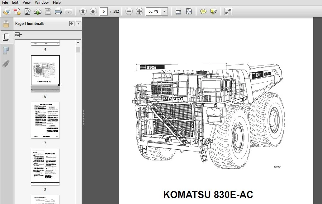
- This manual is provided to aid assemblers during field assembly of the standard Komatsu 830E-AC dump truck. Variations of design required for specific truck orders may require some modification of the general procedures outlined in this manual. Follow all safety notices, warnings, and cautions provided in this book when assembling the truck.
- General assembly pictures and illustrations are used in this manual. At times the illustrations may not reflect the current production truck model.
- This manual lists metric (SI) and U.S. standard dimensions throughout.
- All location references to “front”, “rear”, “right”, or “left”, are given in respect to the operator’s normal seated position. It is recommended that all maintenance personnel read and understand the materials in the service manual before performing maintenance and/or operational checks on the assembled truck.
TABLE OF CONTENTS:
KOMATSU 830E-1AC DUMP TRUCK FIELD ASSEMBLY MANUAL (SN:A30561 A30565) KOMATSU 830E 1AC
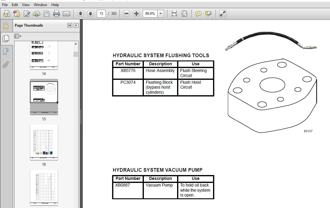
COVER
.................................................................  1
FOREWORD
..............................................................  3
TABLE OF CONTENTS
.....................................................  5
SAFETY RULES, TOOLS & EQUIPMENT........................................  7
	SAFETY RULES.......................................................  7
		BODY-UP RETENTION CABLE........................................  7
	HYDRAULIC SYSTEM FLUSHING TOOLS.................................... 15
	HYDRAULIC SYSTEM VACUUM PUMP....................................... 15
TRUCK COMPONENTS AND SPECIFICATIONS.................................... 19
	Truck And Engine................................................... 19
	AC Induction Traction Motorized Wheels............................. 19
	Suspension......................................................... 19
	Operator's Cab..................................................... 19
	Power Steering..................................................... 19
	Dynamic Retarding.................................................. 19
	Brake System....................................................... 19
	SPECIFICATIONS..................................................... 21
MAJOR COMPONENT WEIGHTS
............................................... 23
FIELD WELDING FOR ASSEMBLY OR REPAIR
.................................. 25
	WELD PROCEDURES.................................................... 25
	APPROVED CONSUMABLES............................................... 25
	WELD QUALITY REQUIREMENTS.......................................... 25
	MATERIALS, CONTROLS, AND PRECAUTIONS............................... 26
	WELD INSPECTION.................................................... 26
	RECORDS............................................................ 27
	ANNEX A............................................................ 27
	ANNEX B............................................................ 29
		1.0 TOE HAMMER PEENING......................................... 29
			Procedure.................................................. 29
		2.0 TOE GRINDING WITH A ROTARY BURR............................ 29
			Procedure.................................................. 29
	BIBLIOGRAPHY....................................................... 32
		SPECIAL PRECAUTIONS WHEN SERVICING AN AC DRIVE SYSTEM TRUCK.... 32
			General Welding Guidelines................................. 33
RECEIVING & ASSEMBLY PREPARATION....................................... 35
	ASSEMBLY LAYOUT.................................................... 36
CHASSIS ASSEMBLY....................................................... 37
	RECOMMENDED ASSEMBLY DATA.......................................... 37
	BASIC ASSEMBLY PROCEDURE........................................... 37
		ORDER OF ASSEMBLY.............................................. 38
		LEVEL 1........................................................ 38
		LEVEL 2........................................................ 38
		LEVEL 7........................................................ 38
	GENERAL PRECAUTIONS AND INSTRUCTION................................ 40
		"Turn-Of-The-Nut" Tightening Procedure......................... 66
		Upper Mounting Joint - 60° Advance............................. 66
		Lower Mounting Joint - 90° Advance............................. 67
		Inspection..................................................... 68
DUMP BODY ASSEMBLY
....................................................125
	BODY ASSEMBLY......................................................126
	BODY WELDING.......................................................128
FINAL ASSEMBLY.........................................................133
FINAL CHECKOUT
........................................................161
APPENDIX...............................................................163
	LUBRICATION CHART..................................................165
	OILING AND CHARGING PROCEDURE......................................167
		GENERAL........................................................167
		EQUIPMENT LIST.................................................167
		HYDRAIR® CHARGING KIT..........................................168
			Installation of Charging Kit...............................168
			Removal of Charging Kit....................................168
		SUPPORT BLOCKS FOR OILING AND CHARGING DIMENSIONS..............169
		FRONT SUSPENSION...............................................169
			Front Suspension Oiling....................................169
			Front Suspension Nitrogen Charging.........................171
		REAR SUSPENSION................................................172
			Rear Suspension Oiling.....................................173
			Rear Suspension Nitrogen Charging..........................174
		OIL AND NITROGEN SPECIFICATIONS CHART..........................176
	TOE-IN ADJUSTMENT..................................................177
	AUTOMATIC LUBRICATION SYSTEM.......................................179
		GENERAL DESCRIPTION............................................179
		SYSTEM COMPONENTS..............................................181
			Filter.....................................................181
			Hydraulic Motor and Pump...................................181
			Grease Reservoir...........................................181
			Pressure Reducing Valve....................................181
			Flow Control Valve.........................................181
			Solenoid Valve.............................................181
			Vent Valve.................................................181
			Lubrication Cycle Timer....................................181
			Over Pressure Cut Off Switch...............................181
			Grease Pressure Failure Switch.............................181
			Injectors..................................................181
			Relief Valve (unloader valve)..............................181
		SYSTEM OPERATION...............................................182
			Normal Operation...........................................182
			Lubricant Required For System..............................183
			System Priming.............................................183
			Filter Assembly............................................183
		LUBRICANT PUMP.................................................184
			Pump Housing Oil Level.....................................184
			Pump Pressure Control......................................184
		SYSTEM CHECKOUT................................................185
			Lubrication Controller Check...............................185
			Lubrication Controller Components..........................185
			Lubrication Controller Adjustment..........................185
		SYSTEM TROUBLESHOOTING CHART...................................187
		STANDARD TORQUE CHARTS AND CONVERSION TABLES...................343
	A/C CHECKOUT PROCEDURE
............................................189
	A/C DRIVE BELT
....................................................191
	HYDRAULIC SYSTEM CHECKOUT PROCEDURE
...............................193
	BRAKE SYSTEM CHECKOUT
.............................................205
	VHMS CHECKOUT PROCEDURE
...........................................215
	INTERFACE MODULE CHECKOUT PROCEDURE
...............................219
	ADDITIONAL INTERFACE MODULE CHECKOUT PROCEDURES
...................227
	PAYLOAD METER CHECKOUT PROCEDURE
..................................235
	ELECTRIC DRIVE SYSTEM CHECKOUT PROCEDURE
..........................249
	AMENDMENTS TO ELECTRIC DRIVE SYSTEM CHECKOUT PROCEDURE
............338
	STANDARD TORQUE CHARTS AND CONVERSION TABLES
......................343
	HYDRAULIC SYSTEM FLUSHING PROCEDURE................................349
		SYSTEM FLUSHING................................................349
			Hydraulic System Flushing Procedure........................349
	STATIC BRAKE SYSTEM CHECKOUT.......................................355
		STATIC BRAKE SYSTEM CHECKOUT...................................355
			Events.....................................................355
			OPERATION..................................................355
				Description............................................355
				Brake Test Exit Criteria...............................356
			PERFORMING THE BRAKE TESTS.................................356
				Setup..................................................356
				Service Brake Test.....................................357
				Parking Brake Test.....................................358
				Retard System Test:....................................358
	FIELD ASSEMBLY INSPECTION REPORT
..................................359
	50 HOUR POST COMMISSIONING CHECKSHEET
.............................364
PLEASE NOTE:
- This is the SAME exact manual used by your dealers to fix your vehicle.
- The same can be yours in the next 2-3 mins as you will be directed to the download page immediately after paying for the manual.
- Any queries / doubts regarding your purchase, please feel free to contact [email protected]


Gavin Benjamin –
VERY SIMPLE EASY TRANSACTION. GREAT PRODUCT