Komatsu 830E-1Ac Dump Truck Operation & Maintenance Manual SN A30072 – A30078 – PDF DOWNLOAD
Original price was: $36.95.$17.95Current price is: $17.95.
Komatsu 830E-1Ac Dump Truck Operation & Maintenance Manual
Book Code : CEAM018903
SERIAL NUMBERS: A30072 – A30078
Description
Komatsu 830E-1Ac Dump Truck Operation & Maintenance Manual
FILE DETAILS:
Komatsu 830E-1Ac Dump Truck Operation & Maintenance Manual
Model Specification: KOMATSU 830E-1AC DUMP TRUCK
Language: English
File Format: PDF
Total Pages: 182
Requirements: Adobe PDF Reader
ZOOM IN/OUT: YES
Downloadable: YES
KOMATSU 830E-1AC DUMP TRUCK OPERATION & MAINTENANCE MANUAL SN A30072 – A30078 – PDF DOWNLOAD:
IMAGES PREVIEW OF THE MANUAL:
DESCRIPTION:
Komatsu 830E-1Ac Dump Truck Operation & Maintenance Manual
FOREWORD:
- This manual is written for use by the operator and/or the service technician and is designed to help these persons to become fully knowledgeable of the truck and all its systems in order to keep it operating safely and efficiently. All operators and maintenance personnel should read and understand the materials in this manual before operating the truck or performing maintenance and/or operational checks on the truck.
- All safety notices, warnings and cautions should be understood and followed when operating or accomplishing repairs on the truck. The first section is an Introduction to the manual and contains a Table of Contents to locate specific areas of interest.
- Other sections include Safety, Operation, Maintenance, Specifications, and Optional Equipment. The illustrations used in this manual are TYPICAL of the component shown and may not be an exact reproduction of what is found on the truck.
- A product identification plate is located on the frame in front of the right side front wheel and designates the Truck Model Number, Product Identification Number (vehicle serial number), and Maximum G.V.W. (Gross Vehicle Weight) rating.The KOMATSU Truck Model designation consists of three numbers and one letter (i.e. 930E).
The three numbers represent the basic truck model.
The letter “M”, when present, designates a Mechanical drive system;
The letter “E”, when present, designates an Electrical wheel motor drive system.
- The Product Identification Number (vehicle serial number) contains information which will identify the original manufacturing bill of material for this unit. This complete number will be necessary for proper ordering of many service parts and/or warranty consideration.
TABLE OF CONTENTS:
Komatsu 830E-1Ac Dump Truck Operation & Maintenance Manual
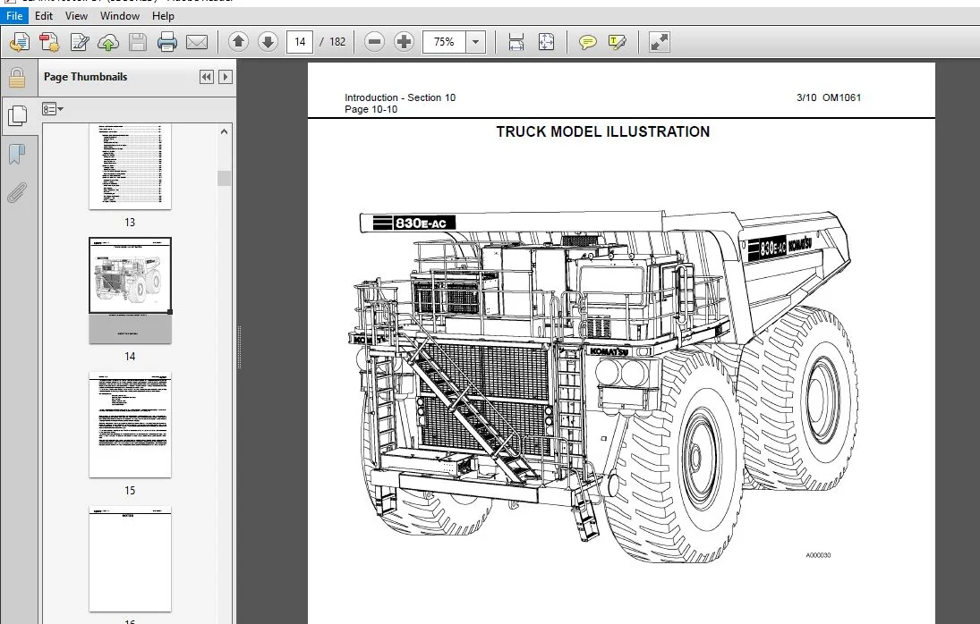
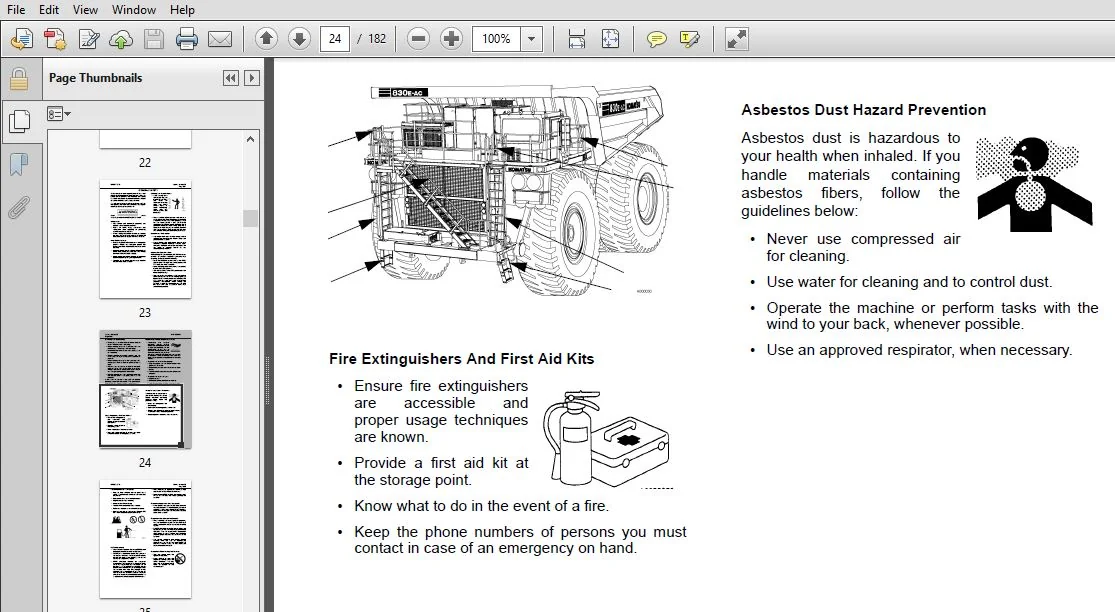
COVER.........................................................................  1
WARNING.......................................................................  3
NON OEM PARTS.................................................................  4
FOREWORD......................................................................  5
	ALERTS PAGE...............................................................  6
TABLE OF CONTENTS.............................................................  7
	TRUCK MODEL ILLUSTRATION.................................................. 14
	ABOUT THIS MANUAL......................................................... 15
STANDARD CHARTS AND TABLES.................................................... 17
GENERAL SAFETY................................................................ 23
	GENERAL SAFETY............................................................ 23
		Safety Rules.......................................................... 23
		Truck Safety Features................................................. 23
		Clothing And Personal Items........................................... 23
		Unauthorized Modification............................................. 23
		Leaving The Operator’s Seat........................................... 23
		Mounting And Dismounting.............................................. 24
		Fire Extinguishers And First Aid Kits................................. 24
		Precautions For High Temperature Fluids............................... 24
		Asbestos Dust Hazard Prevention....................................... 24
		Fire Prevention For Fuel And Oil...................................... 25
		ROPS Precautions...................................................... 25
		Preventing Injury From Work Equipment................................. 25
		Precautions For Optional Attachments.................................. 25
		Precautions When Starting The Machine................................. 25
	PRECAUTIONS FOR TRUCK OPERATION........................................... 26
		Safety Is Thinking Ahead.............................................. 26
		Safety At The Worksite................................................ 26
		Fire Prevention....................................................... 26
		Preparing For Operation............................................... 26
		Ventilation For Enclosed Areas........................................ 26
		Mirrors, Windows, And Lights.......................................... 27
		In The Operator’s Cab - Before Starting The Engine.................... 27
		Seat Belts............................................................ 27
	OPERATING THE MACHINE..................................................... 27
		Starting The Engine................................................... 27
		Truck Operation - General............................................. 27
		Traveling In The Truck................................................ 28
		Precautions When Traveling In Reverse................................. 28
		Traveling On Slopes................................................... 28
		Ensuring Good Visibility.............................................. 29
		Operating On Snow..................................................... 29
		Avoid Damage To The Dump Body......................................... 29
		Driving Near High Voltage Cables...................................... 29
		When Loading The Truck................................................ 29
		When Dumping.......................................................... 29
		Working On Loose Ground............................................... 30
		Parking The Machine................................................... 30
	TOWING.................................................................... 30
	WORKING NEAR BATTERIES.................................................... 31
		Battery Hazard Prevention............................................. 31
		Jump Starting With Booster Cables..................................... 32
		Jump Starting With Receptacles........................................ 32
	BEFORE PERFORMING MAINTENANCE............................................. 33
		Stopping The Engine Before Service.................................... 33
		Warning Tag........................................................... 33
		Proper Tools.......................................................... 33
		Securing The Dump Body................................................ 33
	DURING MAINTENANCE........................................................ 34
		Personnel............................................................. 34
		Attachments........................................................... 34
		Working Under The Machine............................................. 34
		Keeping The Machine Clean............................................. 34
		Rules To Follow When Adding Fuel Or Oil............................... 34
		Radiator Coolant Level................................................ 34
		Use Of Lighting....................................................... 34
		Precautions With The Battery.......................................... 35
		Handling High Pressure Hoses.......................................... 35
		Precautions With High Pressure Oil.................................... 35
		Maintenance Near High Temperatures And High Pressures................. 35
		Rotating Fan And Belts................................................ 35
		Waste Materials....................................................... 35
	TIRES..................................................................... 36
		Handling Tires........................................................ 36
		Tire Maintenance...................................................... 37
		Storing Tires After Removal........................................... 37
		Preliminary Procedures before Welding or Performing Maintenance....... 40
		Engine Shutdown Procedure before Welding or Performing Maintenance.... 40
	ADDITIONAL JOB SITE RULES................................................. 38
	WHEN REPAIRS ARE NECESSARY................................................ 39
	SPECIAL PRECAUTIONS FOR WORKING ON A 830E-AC TRUCK........................ 40
WARNINGS AND CAUTIONS......................................................... 43
TRUCK OPERATION............................................................... 55
	PREPARING FOR OPERATION................................................... 55
		Safety Is Thinking Ahead.............................................. 55
	WALK AROUND INSPECTION.................................................... 55
		FIGURE 30-1. WALK AROUND INSPECTION................................... 56
	ENGINE START-UP SAFETY PRACTICES.......................................... 59
	AFTER ENGINE HAS STARTED.................................................. 60
	EMERGENCY STEERING SYSTEM................................................. 61
		Operation............................................................. 61
		Pre-Operation Testing................................................. 61
		Additional Guidelines................................................. 62
	MACHINE OPERATION SAFETY PRECAUTIONS...................................... 62
	MACHINE OPERATION ON THE HAUL ROAD........................................ 63
	STARTING ON A GRADE WITH A LOADED TRUCK................................... 64
	PASSING................................................................... 64
	LOADING................................................................... 64
	DUMPING................................................................... 64
		Raising The Dump Body................................................. 64
		Lowering The Dump Body................................................ 65
		Lowering The Dump Body................................................ 66
	SUDDEN LOSS OF ENGINE POWER............................................... 66
	FUEL DEPLETION............................................................ 67
	SAFE PARKING PROCEDURES................................................... 67
	NORMAL ENGINE SHUTDOWN PROCEDURE.......................................... 68
	DELAYED ENGINE SHUTDOWN PROCEDURE......................................... 69
	DISABLED TRUCK DUMPING PROCEDURE.......................................... 70
		GENERAL............................................................... 70
		STEERING AND BRAKE SYSTEM............................................. 70
			Hookup............................................................ 70
		HOIST SYSTEM.......................................................... 71
			FIGURE 30-3. HOIST CONNECTIONS.................................... 71
			Hookup............................................................ 71
			Dumping Procedure................................................. 71
	TOWING.................................................................... 72
	RESERVE ENGINE OIL SYSTEM (Optional)...................................... 73
		Operation............................................................. 73
		LED Monitor Light..................................................... 73
		Changing Oil.......................................................... 73
OPERATOR CAB AND CONTROLS..................................................... 75
	STEERING WHEEL AND CONTROLS............................................... 76
		Horn Button........................................................... 76
		Tilt / Telescope Lever................................................ 76
		Multi-Function Turn Signal Switch..................................... 76
		Turn Signal Operation................................................. 76
		High Beam Headlight Operation......................................... 76
		Windshield Wiper Operation............................................ 76
	PEDALS.................................................................... 77
		Service Brake Pedal................................................... 77
		Dynamic Retarding..................................................... 77
		Dynamic Retard Pedal.................................................. 77
		Throttle/Accelerator Pedal............................................ 78
	GRADE/SPEED RETARD CHART.................................................. 78
	OVERHEAD PANEL AND DISPLAYS............................................... 80
		Radio Speakers........................................................ 80
		Warning Alarm Buzzer.................................................. 80
		Cab Radio............................................................. 80
		Warning Light Dimmer Control.......................................... 80
		Status/Warning Indicator Light Panel.................................. 80
		Air Cleaner Vacuum Gauges............................................. 80
		Windshield Wipers..................................................... 80
	CENTER CONSOLE............................................................ 81
		FIGURE 32-3. CENTER CONSOLE........................................... 81
		Directional Control Lever............................................. 81
		Override/Fault Reset Switch........................................... 82
		Engine Stop Switch.................................................... 82
		L.H. Window Control Switch............................................ 82
		R.H. Window Control Switch............................................ 82
		Hoist Control Lever................................................... 82
		Raising The Dump Body................................................. 82
		Lowering The Dump Body................................................ 82
		Retard Speed Control (RSC) Adjust Dial................................ 83
		Retard Speed Control (RSC) Switch..................................... 83
		Data Store Button..................................................... 84
		VHMS Snapshot In Progress Light....................................... 84
		Link Energized Light.................................................. 84
		Service Engine Light.................................................. 84
		DIAGNOSTIC PORTS...................................................... 84
		VHMS Diagnostic Port.................................................. 84
		Interface Module (IM) Diagnostic Port................................. 84
		Payload Meter Diagnostic Port......................................... 84
		Truck Control Interface (TCI) Diagnostic Port......................... 84
		Propulsion System Controller (PSC) Diagnostic Port.................... 84
		Engine Diagnostic Port (CENSE)........................................ 84
		Engine Diagnostic Port (QUANTUM)...................................... 84
	OPERATOR’S SEAT........................................................... 85
		Seat Belts............................................................ 85
		Adjustment............................................................ 85
	HEATER / AIR CONDITIONER COMPARTMENT AND CONTROLS......................... 86
		Fan Control Knob...................................................... 86
		Temperature Control Knob.............................................. 86
		Directional Control Knob.............................................. 86
		Heater Vents.......................................................... 86
	INSTRUMENT PANEL.......................................................... 87
		Key Switch............................................................ 89
		Starting.............................................................. 89
		Engine Stop Switch with Five Minute Idle Timer Delay.................. 89
		Operation............................................................. 89
		Rotating Beacon Light Switch (Optional)............................... 90
		Heated Mirror Switch (Optional)....................................... 90
		Rest Switch........................................................... 90
		Wheel Brake Lock Control.............................................. 90
		Hazard Warning Lights................................................. 90
		Cab/Air Conditioner Vents............................................. 90
		Engine Oil Pressure Gauge............................................. 91
		Right Turn Signal Indicator........................................... 91
		Tachometer............................................................ 91
		High Beam Indicator................................................... 91
		Speedometer/Payload Meter Display..................................... 91
		Left Turn Signal Indicator............................................ 91
		Water Temperature Gauge............................................... 91
		Lamp Test Switch...................................................... 91
		Light Switch.......................................................... 91
		Ladder Light Switch................................................... 92
		Manual Backup Switch.................................................. 92
		Fog Lights (Optional)................................................. 92
		Payload Meter Switch.................................................. 92
		Panel Light Dimmer.................................................... 92
		Hydraulic Oil Temperature Gauge....................................... 93
		Hourmeter............................................................. 93
		Fuel Level Gauge...................................................... 93
	OVERHEAD STATUS / WARNING INDICATORS...................................... 94
		FIGURE 32-8. OVERHEAD STATUS / WARNING INDICATOR...................... 94
		Status / Warning Indicator Light Symbols.............................. 95
	VEHICLE HEALTH MONITORING SYSTEM (VHMS)...................................100
		Operation.............................................................100
		Interface Module......................................................101
		Basic Precautions.....................................................101
	FUSE BLOCKS...............................................................102
	CIRCUIT BREAKERS..........................................................104
LUBRICATION AND SERVICE.......................................................105
	830E SERVICE CAPACITIES...................................................105
	HYDRAULIC TANK SERVICE....................................................105
		Adding Oil............................................................105
	WHEEL MOTOR SERVICE.......................................................105
	COOLANT LEVEL CHECK.......................................................106
	RADIATOR FILLING PROCEDURE................................................106
	RESERVE ENGINE OIL SYSTEM (Optional)......................................106
		Reserve Oil Tank Filling Procedure (Remote fill)......................106
	LUBRICATION CHART.........................................................107
	10 HOUR (DAILY) INSPECTION................................................108
	50 HOUR LUBRICATION AND MAINTENANCE CHECKS................................111
	100 HOUR LUBRICATION AND MAINTENANCE CHECKS...............................112
	250 HOUR LUBRICATION AND MAINTENANCE CHECKS...............................113
	500 HOUR LUBRICATION AND MAINTENANCE CHECKS...............................116
	500 HOUR LUBRICATION AND MAINTENANCE CHECKS (Continued)...................117
	1000 HOURS LUBRICATION AND MAINTENANCE CHECKS.............................118
	2500 HOUR MAINTENANCE CHECKS..............................................119
	5000 HOUR MAINTENANCE CHECKS..............................................119
	10,000 HOUR MAINTENANCE CHECKS............................................120
AUTOMATIC LUBRICATION SYSTEM..................................................121
	GENERAL DESCRIPTION.......................................................121
		FIGURE 42-1. PUMP & RESERVOIR COMPONENTS..............................121
		FIGURE 42-2. AUTOMATIC LUBRICATION SYSTEM INSTALLATION................122
	SYSTEM COMPONENTS.........................................................123
		Filter................................................................123
		Hydraulic Motor and Pump..............................................123
		Grease Reservoir......................................................123
		Pressure Reducing Valve...............................................123
		Pressure Gauge........................................................123
		Flow Control Valve....................................................123
		Solenoid Valve........................................................123
		Vent Valve............................................................123
		Lubrication Cycle Timer...............................................123
		Over Pressure Cutoff Switch...........................................123
		Grease Pressure Failure Switch........................................123
		Injectors.............................................................123
		Relief Valve (unloader valve).........................................123
	SYSTEM OPERATION..........................................................124
	GENERAL INSTRUCTIONS......................................................125
		Required Lubricant....................................................125
		System Priming........................................................125
		Filter Assembly.......................................................125
	LUBRICANT PUMP............................................................126
		Pump Housing Oil Level................................................126
		Pump Pressure Control.................................................126
	INJECTORS (SL-1 Series “H”)...............................................127
		Injector Specifications...............................................127
		Injector Adjustment...................................................127
	INJECTOR OPERATION........................................................128
	PREVENTIVE MAINTENANCE PROCEDURES.........................................129
		Daily Lubrication System Inspection...................................129
		250 Hour Inspection...................................................129
		1000 Hour Inspection..................................................129
	SYSTEM CHECKOUT...........................................................130
	SYSTEM TROUBLESHOOTING CHART..............................................132
MAJOR COMPONENT DESCRIPTION...................................................135
PAYLOAD METER III.............................................................139
	Introduction..............................................................141
		Data Summary..........................................................141
		Data Gathering........................................................141
	COMPONENT DESCRIPTION.....................................................142
		System Diagram........................................................142
		Suspension Pressure Sensors...........................................142
		Inclinometer..........................................................142
		Operator Display......................................................142
		Operator Switch.......................................................143
		Speed Input...........................................................143
		Body-Up Switch........................................................143
		Brake Lock Switch.....................................................143
		Payload Meter.........................................................143
		Communications Ports..................................................143
		Key Switch Input......................................................144
		Payload Meter Power...................................................144
		Load Lights...........................................................144
		Wiring and Termination................................................145
		TCI Outputs...........................................................145
	OPERATOR’S DISPLAY AND SWITCH.............................................146
		Reading the Speedometer...............................................146
		Reading the Load Display..............................................146
		Using the Operator ID.................................................146
		Using the Load and Ton Counter........................................146
		Total Ton Counter.....................................................146
		Total Load Counter....................................................147
		Clearing the Counters.................................................147
		Viewing Live Sensor Data..............................................147
		Other Display Messages................................................147
	PAYLOAD OPERATION & CALCULATION...........................................148
		Haul Cycle States.....................................................148
		Haul Cycle Description................................................148
		Load Calculation......................................................149
		Carry Back............................................................149
		Measurement Accuracy..................................................149
	SOURCES FOR PAYLOAD ERROR.................................................149
		Payload Error.........................................................149
		Loading Conditions....................................................150
		Pressure Sensors......................................................150
		Swingloads............................................................150
		Speed and Distance....................................................150
	HAUL CYCLE DATA...........................................................150
		Haul Cycle Data.......................................................151
		Fault Code Data.......................................................154
	PC SOFTWARE OVERVIEW......................................................155
		PC Overview...........................................................155
		System Configuration..................................................155
		Installing the PLMIII Software........................................155
	DOWNLOADING DATA..........................................................156
	PLM III SYSTEM CONFIGURATION..............................................157
		Starting Communications...............................................157
		Displayed Payload Units...............................................157
		Time Units............................................................157
		Connection Menu.......................................................157
		Connecting to the Payload Meter.......................................158
		Configure the Payload Meter...........................................158
		Setting the Date and Time.............................................158
		Setting the Truck Type................................................159
		Setting the Gauge Display Units.......................................159
		Setting the Frame Serial Number.......................................159
		Setting the Truck Number..............................................159
		Setting the Komatsu Distributor.......................................159
		Setting the Komatsu Customer..........................................159
		Clean Truck Tare......................................................160
		Inclinometer Calibration..............................................160
	DATA ANALYSIS.............................................................161
		Creating a Query......................................................161
		Sorting on Truck Unit Number..........................................161
		Sorting on Truck Type.................................................161
		Sorting on Date Range.................................................162
		Sorting on Time Range.................................................162
		Payload Detail Screen.................................................163
		Creating Reports......................................................163
		Summary - one page report.............................................164
		Detailed - multi-page report..........................................164
		Creating Graphs.......................................................165
		Exporting Data........................................................165
		CSV Export............................................................165
		Compressed............................................................166
		Importing Data........................................................167
		Deleting Haul Cycle Records...........................................167
		Viewing Alarms........................................................168
		Deleting Alarm Records................................................168
			OPERATING INSTRUCTIONS............................................171
AM/FM RADIO...................................................................171
	GENERAL RADIO RECEIVER FUNCTIONS..........................................171
		Turning On the Power..................................................171
		One-Hour Timer........................................................171
		Display...............................................................172
		Setting a Default Display.............................................172
		Adjusting the Brightness of the Display...............................172
		Auxiliary Mode........................................................172
		Adjusting the Receiver Settings.......................................172
	USING THE CLOCK...........................................................173
		Setting the Clock.....................................................173
	USING THE ALARM...........................................................173
		Setting the Alarm.....................................................173
		Turning the Alarm Off.................................................173
		Activating Snooze.....................................................173
		Setting Alarm Volume..................................................173
	USING THE RADIO...........................................................174
		Finding a Station.....................................................174
		Setting the Presets...................................................175
	SATELLITE RADIO SERVICE (Optional)........................................175
		Activating Satellite Radio (Optional).................................175
	USING THE WEATHERBAND.....................................................176
	USING THE COMPACT DISC PLAYER.............................................176
		Playing a Compact Disc................................................176
		Button Functions......................................................176
	PLAYING AN MP3 DISC.......................................................177
		MP3 Format Compatibility..............................................177
		Root Directory........................................................177
		Empty Directory or Folder.............................................177
		No Folder.............................................................177
		File Name Display.....................................................177
		Pre-Programmed Playlists..............................................178
		Playing MP3 Files.....................................................178
		Button Functions......................................................178
	TROUBLESHOOTING...........................................................179
PLEASE NOTE:
- This is the same manual used by the DEALERSHIPS to SERVICE your vehicle.
- The manual can be all yours – Once payment is complete, you will be taken to the download page from where you can download the manual. All in 2-5 minutes time!!
- Need any other service / repair / parts manual, please feel free to contact us at heydownloadss @gmail.com . We may surprise you with a nice offer


Wesley Ayaan –