Komatsu 830E-1AC Dump Truck Shop Manual A30210-A30239 – PDF DOWNLOAD
Original price was: $56.95.$33.95Current price is: $33.95.
Komatsu 830E-1AC Dump Truck Shop Manual
SERIAL NUMBERS : A30210 – A30239
Description
Komatsu 830E-1AC Dump Truck Shop Manual A30210-A30239
FILE DETAILS:
Komatsu 830E-1AC Dump Truck Shop Manual A30210-A30239
Language : English
Pages : 1079
Downloadable : Yes
File Type : PDF
Size: 29.3 MB
Book Code: CEBM021102
DESCRIPTION:
Komatsu 830E-1AC Dump Truck Shop Manual
This Shop Manual is written for use by the service technician and is designed to help the technician become fully knowledgeable of the truck and all its systems in order to keep it running and in production. All maintenance personnel should read and understand the materials in this manual before performing maintenance and/or operational checks on the truck. All safety notices, warnings and cautions should be understood and followed when accomplishing repairs on the truck.
- The first section covers component descriptions, truck specifications and safe work practices, as well as other general information. The major portion of the manual pertains to disassembly, service and reassembly. Each major serviceable area is dealt with individually. For example: The disassembly, service and reassembly of the radiator group is discussed as a unit. The same is true of the engine and engine accessories, and so on through the entire mechanical detail of the truck.
- Disassembly should be carried only as far as necessary to accomplish needed repairs. The illustrations used in this manual are, at times, typical of the component shown and may not necessarily depict a specific model. This manual shows dimensioning of metric (SI) and U.S. standard units throughout and all references to “Right”, “Left”, “Front”, or “Rear” are made with respect to the operator’s normal seated position, unless specifically stated otherwise.
- Standard torque requirements are shown in torque charts in the general information section and individual torques are provided in the text in bold face type, such as 135 N·m (100 ft lbs) torque. All torque specifications have ±10% tolerance unless otherwise specified. A Product Identification plate is normally located on the truck frame in front of the right side front wheel and designates the Truck Model Number, Product Identification Number (vehicle serial number), and Maximum G.V.W. (Gross Vehicle Weight) rating.
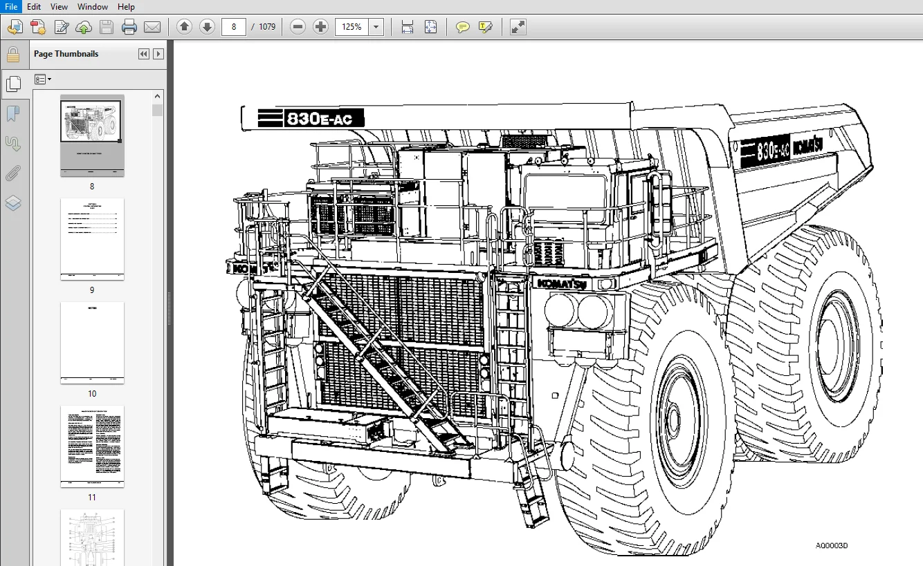
- The KOMATSU Truck Model designation consists of three numbers and one letter (i.e. 830E). The three numbers represent the basic truck model. The letter “E” designates an Electrical propulsion system. The Product Identification Number (vehicle serial number) contains information which will identify the original manufacturing bill of material for this unit. This complete number will be necessary for proper ordering of many service parts and/or warranty consideration.
TABLE OF CONTENTS:
Komatsu 830E-1AC Dump Truck Shop Manual
COVER .............................................................................................. 1 FOREWORD .......................................................................................... 5 TABLE OF CONTENTS .................................................................................. 7 SECTION A: GENERAL INFORMATION .................................................................... 9 MAJOR COMPONENT DESCRIPTION..................................................................... 11 Truck And Engine............................................................................ 11 AC Induction Traction Motorized Wheels...................................................... 11 Suspension.................................................................................. 11 Operator's Cab.............................................................................. 11 Power Steering.............................................................................. 11 Dynamic Retarding........................................................................... 11 Brake System................................................................................ 11 SPECIFICATIONS.............................................................................. 13 GENERAL SAFETY AND OPERATING INSTRUCTIONS....................................................... 15 GENERAL SAFETY.............................................................................. 19 Safety Rules............................................................................ 19 Truck Safety Features................................................................... 19 Clothing And Personal Items............................................................. 19 Unauthorized Modification............................................................... 19 Leaving The Operator’s Seat............................................................. 19 Mounting And Dismounting................................................................ 20 Fire Extinguishers And First Aid Kits................................................... 20 Precautions For High Temperature Fluids................................................. 20 Asbestos Dust Hazard Prevention......................................................... 20 Fire Prevention For Fuel And Oil........................................................ 21 ROPS Precautions........................................................................ 21 Preventing Injury From Work Equipment................................................... 21 Precautions For Optional Attachments.................................................... 21 Precautions When Starting The Machine................................................... 21 PRECAUTIONS FOR TRUCK OPERATION............................................................. 22 Safety Is Thinking Ahead................................................................ 22 Safety At The Worksite.................................................................. 22 Fire Prevention......................................................................... 22 Preparing For Operation................................................................. 22 Ventilation For Enclosed Areas.......................................................... 22 Mirrors, Windows, And Lights............................................................ 23 In The Operator’s Cab - Before Starting The Engine...................................... 23 Seat Belts.............................................................................. 23 OPERATING THE TRUCK......................................................................... 23 Starting The Engine..................................................................... 23 Truck Operation - General............................................................... 23 Traveling In The Truck.................................................................. 24 Precautions When Traveling In Reverse................................................... 24 Traveling On Slopes..................................................................... 24 Ensuring Good Visibility................................................................ 25 Operating On Snow....................................................................... 25 Avoid Damage To The Dump Body........................................................... 25 Driving Near High Voltage Cables........................................................ 25 When Loading The Truck.................................................................. 25 When Dumping............................................................................ 25 Working On Loose Ground................................................................. 26 Parking The Machine..................................................................... 26 TOWING...................................................................................... 26 WORKING NEAR BATTERIES...................................................................... 27 Jump Starting With Booster Cables....................................................... 28 Jump Starting With Receptacles.......................................................... 28 PRECAUTIONS FOR MAINTENANCE................................................................. 29 BEFORE PERFORMING MAINTENANCE............................................................... 29 Stopping The Engine Before Service...................................................... 29 Electrical Systems Isolation............................................................ 29 Warning Tag............................................................................. 31 Proper Tools............................................................................ 31 Securing The Dump Body.................................................................. 31 WHILE PERFORMING MAINTENANCE................................................................ 32 Personnel............................................................................... 32 Attachments............................................................................. 32 Working Under The Machine............................................................... 32 Keeping The Machine Clean............................................................... 32 Rules To Follow When Adding Fuel Or Oil................................................. 32 Radiator Coolant Level.................................................................. 32 Use Of Lighting......................................................................... 32 Precautions With The Battery............................................................ 33 Handling High Pressure Hoses............................................................ 33 Precautions With High Pressure Oil...................................................... 33 Maintenance Near High Temperatures And High Pressures................................... 33 Rotating Fan And Belts.................................................................. 33 Waste Materials......................................................................... 33 TIRES....................................................................................... 34 Handling Tires.......................................................................... 34 Tire Maintenance........................................................................ 35 Storing Tires After Removal............................................................. 35 ADDITIONAL JOB SITE RULES................................................................... 36 WHEN REPAIRS ARE NECESSARY.................................................................. 37 Use of Tie-Off Anchor During Maintenance................................................ 37 SPECIAL PRECAUTIONS FOR WORKING ON AN 830E-1AC TRUCK........................................ 38 Preliminary Procedures before Welding or Performing Maintenance......................... 38 Engine Shutdown Procedure before Welding or Performing Maintenance...................... 38 CAPACITOR DISCHARGE SYSTEM.................................................................. 40 Necessary Tools......................................................................... 40 Warnings And Cautions................................................................... 41 MANUAL DC LINK CAPACITOR DISCHARGE PROCEDURE............................................ 42 Preparation......................................................................... 42 CAPACITOR CHARGE LIGHTS................................................................. 44 FAILURE OF DISCHARGE SYSTEM............................................................. 45 Measuring Dc Voltage On Capacitors.................................................. 45 MANUAL DISCHARGE OF CAPACITORS.......................................................... 46 SHORT ISOLATED CAPACITOR TERMINALS...................................................... 48 OPERATING INSTRUCTIONS...................................................................... 50 PREPARING FOR OPERATION................................................................. 50 Safety Is Thinking Ahead............................................................ 50 WALK AROUND INSPECTION.................................................................. 50 RETRACTABLE LADDER SYSTEM (If equipped)................................................. 54 LADDER SYSTEM DESCRIPTION........................................................... 54 LADDER SYSTEM OPERATION............................................................. 55 Normal Operation................................................................ 55 GENERAL SAFETY...................................................................... 55 IN-CAB CONTROL PANEL................................................................ 55 IN-CAB CONTROL PANEL FEATURES....................................................... 56 Digital Display Screen.......................................................... 56 Command Buttons................................................................. 56 USING THE IN-CAB CONTROL PANEL...................................................... 57 Raising the Ladder.............................................................. 57 Lowering the Ladder............................................................. 58 USING THE GROUND LEVEL CONTROL BOX.................................................. 59 Raising the Ladder.............................................................. 59 Lowering the Ladder............................................................. 59 Emergency Operation............................................................. 60 ENGINE START-UP SAFETY PRACTICES........................................................ 61 AFTER ENGINE HAS STARTED................................................................ 62 PRE-SHIFT BRAKE CHECK (if equipped)..................................................... 63 Events.............................................................................. 63 OPERATION........................................................................... 63 Description..................................................................... 63 Brake Test Exit Criteria........................................................ 64 PERFORMING THE BRAKE TESTS.......................................................... 64 Setup........................................................................... 64 Service Brake Test.............................................................. 65 Parking Brake Test.............................................................. 66 Retard System Test:............................................................. 66 EMERGENCY STEERING SYSTEM............................................................... 67 Operation........................................................................... 67 Pre-Operation Testing............................................................... 67 Additional Guidelines............................................................... 68 MACHINE OPERATION SAFETY PRECAUTIONS.................................................... 68 MACHINE OPERATION ON THE HAUL ROAD...................................................... 69 STARTING ON A GRADE WITH A LOADED TRUCK................................................. 70 PASSING................................................................................. 70 LOADING................................................................................. 70 DUMPING................................................................................. 70 Raising The Dump Body............................................................... 70 Lowering The Dump Body.............................................................. 71 SUDDEN LOSS OF ENGINE POWER............................................................. 73 FUEL DEPLETION.......................................................................... 73 SAFE PARKING PROCEDURES................................................................. 74 NORMAL ENGINE SHUTDOWN PROCEDURE........................................................ 74 DISABLED TRUCK CONNECTORS................................................................... 75 GENERAL................................................................................. 75 STEERING AND BRAKE SYSTEM............................................................... 75 Hookup.............................................................................. 75 HOIST SYSTEM............................................................................ 76 Hookup.............................................................................. 77 Dumping Procedure................................................................... 77 TOWING...................................................................................... 78 Special Wiring Harness.................................................................. 78 Towing Procedure........................................................................ 78 RESERVE ENGINE OIL SYSTEM (Optional)........................................................ 81 Operation............................................................................... 81 WARNINGS AND CAUTIONS........................................................................... 83 TORQUE TABLES AND CONVERSION CHARTS ............................................................ 97 STORAGE PROCEDURES.............................................................................. 107 STORAGE AND IDLE MACHINE PREPARATION........................................................ 109 SHORT TERM IDLE PERIODS................................................................. 109 PREPARATION FOR STORAGE................................................................. 110 REMOVAL FROM STORAGE.................................................................... 111 RECONDITIONING AN IDLE VEHICLE.......................................................... 113 ENGINE OPERATION........................................................................ 115 AFTER ENGINE HAS STARTED................................................................ 116 ENGINE STORAGE.......................................................................... 117 Engine Storage-(Short Term)......................................................... 117 Engine Storage- (Long Term)......................................................... 118 TRANSMISSION PRESERVATION AND STORAGE................................................... 123 Restoring Transmission to Service................................................... 123 ELECTRIC DRIVE TRUCKS................................................................... 119 SECTION B: STRUCTURES .............................................................................. 125 STRUCTURAL COMPONENTS........................................................................... 127 STRUCTURAL COMPONENTS....................................................................... 129 Preparation............................................................................. 129 LADDERS................................................................................. 130 Removal............................................................................. 130 Installation........................................................................ 130 RIGHT DECK.............................................................................. 130 Removal............................................................................. 130 Installation........................................................................ 132 LEFT DECK............................................................................... 132 Removal............................................................................. 132 Installation........................................................................ 133 CENTER DECK............................................................................. 133 DUMP BODY....................................................................................... 135 DUMP BODY................................................................................... 137 Removal................................................................................. 137 Installation............................................................................ 138 BODY PADS............................................................................... 139 Removal............................................................................. 139 Installation........................................................................ 139 Adjustment.......................................................................... 140 BODY GUIDE.............................................................................. 141 BODY-UP RETENTION CABLE................................................................. 142 BODY POSITION INDICATOR................................................................. 142 HOIST LIMIT SWITCH...................................................................... 142 BODY UP SWITCH.......................................................................... 142 ROCK EJECTORS........................................................................... 143 Inspection.......................................................................... 143 FUEL TANK....................................................................................... 145 FUEL TANK................................................................................... 146 Removal................................................................................. 146 Installation............................................................................ 146 Repair.................................................................................. 148 Cleaning................................................................................ 148 FUEL GAUGE SENDER....................................................................... 148 Removal............................................................................. 148 Installation........................................................................ 148 FUEL TANK BREATHER VALVE................................................................ 149 Disassembly......................................................................... 149 Assembly............................................................................ 149 FUEL RECEIVERS (WIGGINS QUICK FILL)..................................................... 150 SECTION C: ENGINE .................................................................................. 151 POWER MODULE.................................................................................... 153 POWER MODULE................................................................................ 155 PREPARATION............................................................................. 155 Removal............................................................................. 155 Installation........................................................................ 160 COOLING SYSTEM.................................................................................. 165 COOLING SYSTEM DESCRIPTION.................................................................. 167 RADIATOR................................................................................ 168 Removal............................................................................. 168 Installation........................................................................ 171 Radiator Filling Procedure.......................................................... 172 REPAIRING THE RADIATOR.................................................................. 173 Internal Inspection................................................................. 173 External Cleaning................................................................... 173 Disassembly......................................................................... 173 Cleaning and Inspection............................................................. 174 Assembly............................................................................ 174 Pressure Testing.................................................................... 176 COOLANT SYSTEM TROUBLESHOOTING.......................................................... 176 POWER TRAIN..................................................................................... 177 ALTERNATOR REMOVAL PROCEDURE................................................................ 179 Removal (Komatsu SSDA16V160 or SDA16V160 Engine)........................................ 179 ENGINE/ALTERNATOR MATING.................................................................... 181 General Instructions.................................................................... 181 Measuring Procedure..................................................................... 181 Joining Alternator and Komatsu SSDA16V160 or SDA16V160 Engine........................... 183 ENGINE...................................................................................... 184 Removal................................................................................. 184 Service................................................................................. 185 Installation............................................................................ 185 AIR CLEANERS.................................................................................... 187 AIR CLEANERS................................................................................ 189 OPERATION............................................................................... 189 SERVICING THE AIR CLEANERS.............................................................. 189 Replacing The Filter Element........................................................ 190 AIR CLEANER ASSEMBLY CLEANING........................................................... 191 Main Filter Cleaning................................................................ 191 Precleaner Section Cleaning......................................................... 193 AIR INTAKE TROUBLESHOOTING.............................................................. 194 FAN CLUTCH ..................................................................................... 195 FAN CLUTCH.................................................................................. 197 REMOVAL & INSTALLATION TOOLING.......................................................... 197 DISASSEMBLY............................................................................. 200 CLEANING AND INSPECTION................................................................. 210 ASSEMBLY................................................................................ 214 TEST PROCEDURE.......................................................................... 228 SECTION D: 24V DC ELECTRICAL SYSTEM ................................................................ 229 24VDC ELECTRIC SUPPLY SYSTEM.................................................................... 231 24VDC ELECTRIC SUPPLY SYSTEM................................................................ 233 ELECTRICAL SYSTEM DESCRIPTION........................................................... 233 BATTERIES............................................................................... 233 Maintenance and Service............................................................. 233 Troubleshooting..................................................................... 233 BATTERY SUPPLY SYSTEM................................................................... 235 24VDC Battery Charging Alternator................................................... 235 Battery Box......................................................................... 235 Removal............................................................................. 236 Installation........................................................................ 236 Battery Control Box................................................................. 237 24VDC Auxiliary Battery Receptacles................................................. 237 Isolator Diode...................................................................... 237 Engine Start Relay.................................................................. 237 Isolation Box Assembly.............................................................. 237 Engine Shutdown Switch.............................................................. 238 Access Ladder Light Switch.......................................................... 238 Battery Disconnect Switches......................................................... 238 Propel Lockout Lever................................................................ 238 LED Lights.......................................................................... 238 24VDC to 12VDC Converter............................................................ 238 24VDC ELECTRIC CRANKING MOTOR SYSTEM (WITH PRELUBE)..................................... 239 Operation........................................................................... 239 Pressure Switch..................................................................... 240 Check Valve......................................................................... 240 Timer Solenoid...................................................................... 240 MAINTENANCE............................................................................. 240 Prelube System Operation Checks..................................................... 240 Check Valve......................................................................... 240 Timer Solenoid...................................................................... 240 TROUBLESHOOTING PRELUBE CRANKING MOTOR CIRCUIT.............................................. 241 24VDC ELECTRIC START SYSTEM................................................................. 243 CRANKING MOTORS......................................................................... 243 Operation........................................................................... 243 Removal............................................................................. 243 Installation........................................................................ 243 CRANKING MOTOR TROUBLESHOOTING.......................................................... 244 Preliminary Inspection.............................................................. 244 No-Load Test........................................................................ 244 Interpreting Results of Tests....................................................... 245 Disassembly......................................................................... 245 Cleaning and Inspection............................................................. 246 Armature Servicing.................................................................. 248 Field Coil Checks................................................................... 248 Field Coil Removal.................................................................. 248 SOLENOID CHECKS......................................................................... 249 Test................................................................................ 249 Assembly............................................................................ 250 Bearing Replacement:................................................................ 250 Motor Assembly:..................................................................... 250 Pinion Clearance.................................................................... 251 MAGNETIC SWITCH......................................................................... 251 Removal............................................................................. 251 Installation........................................................................ 251 Coil Test........................................................................... 252 24VDC ELECTRICAL SYSTEM COMPONENTS.............................................................. 253 24 VDC ELECTRICAL SYSTEM COMPONENTS......................................................... 255 TRUCK SHUTDOWN PROCEDURE................................................................ 255 BRAKE WARNING BUZZER.................................................................... 255 AUXILIARY CONTROL CABINET COMPONENTS.................................................... 255 Power Distribution Terminals........................................................ 255 Pulse Voltage Modulator (PMV)....................................................... 256 Control Power Relay................................................................. 256 Auto Lube Timer..................................................................... 256 Ground Level Power Relay............................................................ 256 Diode Board - DB1................................................................... 258 Fuse Blocks......................................................................... 259 Alarm Indicating Device (AID) System................................................ 259 Diode Matrix (With Sound)........................................................... 260 Diode Matrix (Without Sound)........................................................ 260 Hot Switch Inverter................................................................. 260 Hot Switch Inverter (Not Used)...................................................... 261 Temperature and Latch............................................................... 261 RELAY BOARDS............................................................................ 262 Relay Boards RB1, RB3, RB4, RB5..................................................... 262 Relay Boards RB6, RB7, RB8, RB9..................................................... 263 Service............................................................................. 263 Relay Board Functions............................................................... 265 BODY-UP SWITCH.......................................................................... 267 Operation........................................................................... 267 Adjustment.......................................................................... 267 Service............................................................................. 267 HOIST LIMIT SWITCH...................................................................... 268 Operation........................................................................... 268 Adjustment.......................................................................... 268 Service............................................................................. 268 FUSE BLOCK CHARTS....................................................................... 269 CIRCUIT BREAKER CHART................................................................... 271 CIRCUIT BREAKERS........................................................................ 271 KOMTRAX Plus SYSTEM ............................................................................ 273 KOMTRAX Plus COMPONENTS..................................................................... 275 KOMTRAX Plus BASIC FEATURES............................................................. 275 Gather Data......................................................................... 275 Convert and Record Data............................................................. 275 Communicate Data to Off-Board Systems............................................... 276 USING THE KOMTRAX Plus SYSTEM........................................................... 277 Turning the KOMTRAX Plus System ON.................................................. 277 Normal KOMTRAX Plus Operation....................................................... 277 Turning the KOMTRAX Plus System OFF................................................. 278 Downloading from the KOMTRAX Plus Controller........................................ 278 KOMTRAX Plus DATA ITEMS................................................................. 279 Fault Codes......................................................................... 279 Machine History..................................................................... 279 KOMTRAX Plus History................................................................ 279 Snapshots........................................................................... 280 Manual Snapshots.................................................................... 280 Trends.............................................................................. 282 Histogram (Load Map) Data........................................................... 282 Haul Cycle Data..................................................................... 283 Alarm and Snapshot Triggers......................................................... 284 Satellite Features.................................................................. 284 KOMTRAX Plus DIAGNOSTIC FEATURES........................................................ 286 Fault History....................................................................... 286 KOMTRAX Plus LED Digits............................................................. 286 KOMTRAX Plus CONTROLLER................................................................. 286 Removal............................................................................. 287 Installation........................................................................ 287 KOMTRAX Plus SOFTWARE................................................................... 289 NECESSARY SOFTWARE.................................................................. 289 NECESSARY TOOLS..................................................................... 289 KOMTRAX Plus SYSTEM SET UP.......................................................... 290 KOMTRAX Plus Controller......................................................... 290 KOMTRAX Plus CONTROLLER............................................................. 290 KOMTRAX Plus TOOL BOX........................................................... 290 Installation................................................................ 290 KOMTRAX Plus SETTING TOOL....................................................... 290 Installation................................................................ 290 KOMTRAX Plus INITIALIZATION PROCEDURE............................................... 291 1. KOMTRAX Plus CONTROLLER SETUP PROCEDURE...................................... 291 KOMTRAX Plus Setting Tool software program.................................. 291 Select Operation............................................................ 291 KOMTRAX Plus Setting Function............................................... 292 Machine Information Setting(1).............................................. 292 Machine Information Setting(2).............................................. 292 Date & Time Setting......................................................... 292 GCC Setting................................................................. 293 Setting Summary............................................................. 293 2. KOMTRAX Plus SNAPSHOT PROCEDURE.............................................. 294 3. KOMTRAX Plus DOWNLOAD PROCEDURE.............................................. 295 4. LOCATION OF DOWNLOAD FILES................................................... 295 5. KOMTRAX Plus FTP UPLOAD PROCEDURE............................................ 296 6. KOMTRAX Plus INITIALIZATION FORMS............................................ 297 WHEN REPLACING A KOMTRAX Plus CONTROLLER............................................ 298 To Set: Date & Time; Satellite; Payload Meter................................... 300 Review Setting Information...................................................... 302 KOMTRAX Plus CONTROLLER CHECKOUT................................................ 303 KOMTRAX Plus Controller..................................................... 303 Necessary Equipment:........................................................ 303 Preliminary................................................................. 304 KOMTRAX Plus Controller Checkout Procedure.................................. 305 ORBCOMM CONTROLLER.............................................................. 307 Removal..................................................................... 307 Installation................................................................ 307 INTERFACE MODULE ............................................................................... 309 INTERFACE MODULE............................................................................ 311 Removal................................................................................. 311 Installation............................................................................ 311 SENSORS................................................................................. 312 Temperature Sensors................................................................. 312 Pressure Sensors.................................................................... 312 INTERFACE MODULE SOFTWARE................................................................... 313 NECESSARY SOFTWARE...................................................................... 313 NECESSARY TOOLS......................................................................... 313 FLASHBURN PROGRAM....................................................................... 314 Installation........................................................................ 314 INTERFACE MODULE APPLICATION CODE....................................................... 314 Installation........................................................................ 314 INTERFACE MODULE REALTIME DATA MONITOR SOFTWARE PROGRAM................................. 314 Installation........................................................................ 314 Using The Program................................................................... 314 INTERFACE MODULE CHECKOUT............................................................... 315 Interface Module.................................................................... 315 Necessary Equipment:................................................................ 315 Preliminary......................................................................... 316 Checking Inputs And Outputs From The Interface Module............................... 316 Check Analog Inputs To The Interface Module......................................... 320 Check CAN RPC & J1939 Interfaces To The IM.......................................... 320 Check Outputs From The Interface Module............................................. 320 KOMTRAX Plus & INTERFACE MODULE TROUBLESHOOTING AND ERROR CODES ................................ 323 KOMTRAX Plus AND INTERFACE MODULE ERROR CODES AND TROUBLESHOOTING........................... 325 TROUBLESHOOTING......................................................................... 325 GENERAL............................................................................. 325 Structure and Purpose........................................................... 325 TROUBLESHOOTING..................................................................... 326 Communications Networks......................................................... 326 Coaxial Cable................................................................... 326 FAULT CODES......................................................................... 327 Fault History................................................................... 327 KOMTRAX Plus LED Display Fault Codes............................................ 328 Chassis Fault Codes............................................................. 329 Engine Fault Codes.............................................................. 333 FAULT TREE ANALYSIS................................................................. 339 Unable to connect to KOMTRAX Plus from laptop PC................................ 339 Flashing Error Code N4-23 (PLM III Communications Fault)........................ 340 Flashing Error Code N4-22 (Engine Communications Fault)......................... 341 No Data Received By WebCARE..................................................... 342 Coaxial Cable Troubleshooting................................................... 343 KOMTRAX PLUS FORMS ............................................................................ 345 KOMTRAX PLUS FORMS.......................................................................... 347 KOMTRAX PLUS INITIALIZATION CHECK LIST.................................................. 347 KOMTRAX PLUS DATA DOWNLOAD.............................................................. 348 KOMTRAX PLUS INITIALIZATION CHECK LIST.................................................. 349 KOMTRAX PLUS INITIALIZATION FORM........................................................ 351 SECTION E: ELECTRIC PROPULSION SYSTEM .............................................................. 353 ELECTRIC PROPULSION SYSTEM COMPONENTS .......................................................... 355 ELECTRICAL PROPULSION SYSTEM COMPONENTS..................................................... 357 GENERAL SYSTEM DESCRIPTION.............................................................. 357 SYSTEM COMPONENTS....................................................................... 359 Propulsion System Controller (PSC).................................................. 359 Truck Control Interface (TCI)....................................................... 360 Diagnostic Information Display (DID) Panel.......................................... 361 DID Panel Event Codes............................................................... 361 PSC SOFTWARE FUNCTIONS.................................................................. 380 Input Processing.................................................................... 380 State Machine....................................................................... 380 DC Link State....................................................................... 383 Engine Control...................................................................... 384 ALTERNATOR FIELD CONTROL................................................................ 384 Desired Three-Phase Voltage......................................................... 384 Desired DC Link Voltage............................................................. 384 Self-Load........................................................................... 385 Propel Torque Control............................................................... 385 Retard Torque Control............................................................... 385 Wheel Slide Control................................................................. 386 Resistor Grid Control............................................................... 386 Chopper Voltage Control............................................................. 386 EVENT DETECTION AND PROCESSING.......................................................... 386 Power-On Tests...................................................................... 386 Initiated Tests..................................................................... 387 Periodic Tests...................................................................... 387 EVENT RESTRICTIONS...................................................................... 387 EVENT LOGGING AND STORAGE............................................................... 387 Event History Buffer................................................................ 388 Data Packs.......................................................................... 388 To Record and Save a Data Pack to a Disk............................................ 388 Event Reset......................................................................... 389 SERIAL DATA COMMUNICATIONS.............................................................. 389 PSC - TCI Communications Processing................................................. 389 PSC - PTU Communications Processing................................................. 389 Inverter Communications Processing.................................................. 390 OUTPUT PROCESSING....................................................................... 390 ABNORMAL CONDITIONS/OVERRIDING FUNCTIONS................................................ 390 Fast Start.......................................................................... 390 Engine Shutdown/Engine Not Running.................................................. 390 Limp Home Mode...................................................................... 391 PROPULSION SYSTEM COMPONENT ABBREVIATIONS & LOCATIONS................................... 392 ELECTRONIC ACCELERATOR AND RETARD PEDALS................................................ 400 Removal............................................................................. 400 Installation........................................................................ 400 Disassembly......................................................................... 400 Assembly............................................................................ 400 AC DRIVE SYSTEM ELECTRICAL CHECKOUT PROCEDURE .................................................. 401 AC DRIVE SYSTEM ELECTRICAL CHECKOUT PROCEDURE............................................... 403 AC DRIVE SYSTEM MAINTENANCE............................................................. 403 NORMAL TRUCK SHUTDOWN PROCEDURE......................................................... 404 SHUTDOWN AFTER SYSTEM FAILURE........................................................... 404 SYSTEM CHECKOUT......................................................................... 405 Battery and Control Circuit Checks - Battery Power OFF.............................. 405 Battery and Control Circuit Checks - Battery Power ON............................... 408 Checks with Key Switch OFF.......................................................... 409 Checks with Key Switch ON........................................................... 409 CPU Battery Checks.................................................................. 409 MEMORY BACKUP BATTERY REPLACEMENT....................................................... 410 TCI PROGRAMMING......................................................................... 410 PSC PROGRAMMING......................................................................... 411 INVERTER PROGRAMMING.................................................................... 411 CPU RESET............................................................................... 411 PSC CHECKOUT............................................................................ 412 PSC Digital Input Checks............................................................ 412 PSC Digital Output Checks........................................................... 416 TCI CHECKOUT............................................................................ 417 Modular Mining Communication Port Check............................................. 417 TCI Digital Input Checks............................................................ 417 TCI Digital Output Tests............................................................ 423 CALIBRATIONS............................................................................ 426 Speedometer......................................................................... 426 Accelerator Pedal, Retarder Pedal/Lever and RSC Dial................................ 426 ERASING EVENTS.......................................................................... 426 PSC................................................................................. 426 TCI................................................................................. 427 GATE DRIVER POWER CONVERTER TEST........................................................ 427 LOAD TESTING............................................................................ 428 Preparation......................................................................... 428 Alternator Speed Sensor Checks...................................................... 428 Battery Boost Check................................................................. 428 Brake Circuit Switch Checks......................................................... 429 Hoist & Steering Circuit Switch Checks.............................................. 429 Link Energized Checks............................................................... 429 Loadbox Test........................................................................ 431 TROUBLESHOOTING......................................................................... 435 PVM Optimum Load Curve Handshaking Troubleshooting.................................. 435 Phase Module and Chopper Module Troubleshooting..................................... 435 PHASE MODULE REPLACEMENT................................................................ 436 Phase Module Removal................................................................ 436 Phase Module Installation........................................................... 436 SECTION G: DRIVE AXLE, SPINDLE, AND WHEELS ......................................................... 437 TIRES AND RIMS.................................................................................. 439 TIRES AND RIMS.............................................................................. 441 FRONT TIRES AND RIMS.................................................................... 441 Removal............................................................................. 441 Installation........................................................................ 443 REAR TIRES AND RIMS..................................................................... 443 Removal............................................................................. 443 Installation........................................................................ 444 RIM AND TIRE............................................................................ 446 Tire Removal........................................................................ 446 Rim And Tire Preparation............................................................ 446 Lubricants.......................................................................... 447 Tire Installation................................................................... 447 FRONT WHEEL HUB AND SPINDLES.................................................................... 449 FRONT WHEEL HUB AND SPINDLE................................................................. 451 WHEEL HUB AND SPINDLE ASSEMBLY.......................................................... 451 Removal............................................................................. 451 Spindle Removal Procedure (Optional) (off of the truck)............................. 454 Installation........................................................................ 456 Disassembly......................................................................... 459 Cleaning and Inspection............................................................. 459 Assembly............................................................................ 460 Wheel Bearing Adjustment (Tire Removed)............................................. 462 Wheel Bearing Adjustment (Tire mounted)............................................. 463 OIL SAMPLING PROCEDURE.................................................................. 464 Oil Sampling Guidelines............................................................. 465 Procedure........................................................................... 465 OIL DRAIN AND REFILL PROCEDURE.......................................................... 465 STEERING CYLINDERS...................................................................... 466 Spherical Bearing Wear Limits....................................................... 466 Removal............................................................................. 467 Installation........................................................................ 467 Bearing Replacement (Steering cylinder and tie rod)................................. 467 TIE ROD................................................................................. 469 Removal............................................................................. 469 Installation........................................................................ 469 Disassembly......................................................................... 469 Assembly............................................................................ 470 TOE-IN ADJUSTMENT....................................................................... 471 REAR AXLE HOUSING ATTACHMENT.................................................................... 473 REAR AXLE HOUSING ATTACHMENT................................................................ 475 PIVOT PIN............................................................................... 475 Removal............................................................................. 475 Installation........................................................................ 475 PIVOT EYE BEARING....................................................................... 476 Disassembly......................................................................... 476 Assembly............................................................................ 476 PIVOT EYE REPAIR........................................................................ 477 Removal............................................................................. 477 Installation........................................................................ 477 Disassembly......................................................................... 477 Assembly............................................................................ 477 ANTI-SWAY BAR........................................................................... 478 Removal............................................................................. 478 Installation........................................................................ 478 Disassembly......................................................................... 478 Cleaning and Inspection............................................................. 478 Assembly............................................................................ 478 REAR AXLE HOUSING............................................................................... 479 REAR AXLE HOUSING........................................................................... 481 REAR AXLE HOUSING....................................................................... 481 Removal............................................................................. 481 Installation........................................................................ 481 WHEEL MOTOR............................................................................. 482 Removal............................................................................. 482 Cleaning and Inspection............................................................. 482 Installation........................................................................ 483 WHEEL MOTOR GEAR OIL.................................................................... 486 Change/Filter The Gear case Oil..................................................... 486 Oil................................................................................. 486 Remove And Clean Magnetic Plugs..................................................... 486 Flushing The Gearbox................................................................ 486 Check Gear Case Oil Level........................................................... 486 SECTION H: SUSPENSIONS INDEX....................................................................... 487 FRONT SUSPENSION................................................................................ 489 FRONT SUSPENSION............................................................................ 491 Removal................................................................................. 491 Installation............................................................................ 492 TURN-OF-THE-NUT Tightening Procedure.................................................... 494 Upper Mounting Joint - 60° Advance.................................................. 494 Lower Mounting Joint - 90° Advance.................................................. 496 Inspection.......................................................................... 496 MINOR REPAIR ONLY (Lower Bearing Structure & Seals)..................................... 497 Bearing Structure Removal........................................................... 497 Bearing Structure Installation...................................................... 497 MAJOR SUSPENSION REBUILD................................................................ 498 Disassembly......................................................................... 498 Assembly............................................................................ 499 PRESSURE TEST........................................................................... 501 REAR SUSPENSIONS ............................................................................... 503 REAR SUSPENSIONS............................................................................ 505 Removal................................................................................. 505 Installation............................................................................ 508 ROD UP SUSPENSION....................................................................... 510 Disassembly......................................................................... 510 Cleaning and Inspection............................................................. 510 Assembly............................................................................ 510 ROD DOWN SUSPENSION..................................................................... 512 Disassembly......................................................................... 512 Cleaning and Inspection............................................................. 512 Assembly............................................................................ 514 PRESSURE TEST........................................................................... 516 Suspension pressure test............................................................ 516 OILING AND CHARGING PROCEDURE................................................................... 517 OILING AND CHARGING PROCEDURE............................................................... 519 GENERAL................................................................................. 519 EQUIPMENT LIST.......................................................................... 519 HYDRAIR® CHARGING KIT................................................................... 520 Installation of Charging Kit........................................................ 520 Removal of Charging Kit............................................................. 520 SUPPORT BLOCKS FOR OILING AND CHARGING DIMENSIONS....................................... 521 FRONT SUSPENSION........................................................................ 521 Front Suspension Oiling............................................................. 521 Front Suspension Nitrogen Charging.................................................. 523 REAR SUSPENSION - ROD UP................................................................ 525 Rear Suspension Oiling (Rod Up Only)................................................ 525 Rear Suspension Nitrogen Charging (Rod Up Only)..................................... 526 REAR SUSPENSION - ROD DOWN.............................................................. 528 Rear Suspension Oiling (Rod Down Only).............................................. 528 Rear Suspension Nitrogen Charging (Rod Down Only)................................... 530 OIL AND NITROGEN SPECIFICATIONS CHART................................................... 532 SECTION J: BRAKE SYSTEM ............................................................................ 533 BRAKE CIRCUIT................................................................................... 535 BRAKE CIRCUIT............................................................................... 537 OPERATION............................................................................... 537 SERVICE BRAKE CIRCUIT OPERATION......................................................... 537 SECONDARY BRAKING AND AUTOMATIC APPLY................................................... 539 PARKING BRAKE CIRCUIT................................................................... 539 Normal Operation (key switch on, engine running).................................... 539 BRAKE LOCK CIRCUIT...................................................................... 540 WARNING CIRCUIT......................................................................... 540 BRAKE CIRCUIT COMPONENT SERVICE................................................................. 543 BRAKE CIRCUIT COMPONENT SERVICE............................................................. 545 BRAKE VALVE............................................................................. 545 Rebuild Criteria.................................................................... 545 Removal............................................................................. 545 Installation........................................................................ 547 DISASSEMBLY............................................................................. 549 Cleaning and Inspection............................................................. 551 ASSEMBLY................................................................................ 551 Actuator Base Threaded Inserts...................................................... 551 Boot and Cap........................................................................ 551 Valve Body Seal Installation........................................................ 552 Regulator Sleeve O-Ring Installation................................................ 552 Actuator Plunger O-ring Installation................................................ 553 Assembly of Valve................................................................... 553 VALVE BENCH TEST AND ADJUSTMENT......................................................... 555 Test Set Up Procedure............................................................... 556 Brake Valve Output Pressure Adjustment.............................................. 556 Final Test and Adjustment........................................................... 557 Installation Of Brake Pedal Actuator Assembly to Brake Valve........................ 558 BRAKE ASSEMBLIES WITH INTEGRAL MOUNTED ELECTRONIC RETARD PEDAL (Dual Function Pedal).... 560 Installation of Retard Pedal To Brake Pedal......................................... 560 HYDRAULIC BRAKE ACCUMULATORS............................................................ 561 Brake Accumulator Bleed Down Procedure.............................................. 561 Removal............................................................................. 561 Installation........................................................................ 561 Disassembly......................................................................... 561 Cleaning and Inspection............................................................. 563 Assembly............................................................................ 563 Charging Procedure.................................................................. 565 BRAKE MANIFOLD.......................................................................... 566 Removal............................................................................. 566 Removal............................................................................. 566 Installation........................................................................ 567 Disassembly......................................................................... 567 Cleaning and Inspection............................................................. 568 Assembly............................................................................ 568 BRAKE CIRCUIT CHECK-OUT PROCEDURE............................................................... 569 BRAKE CIRCUIT CHECK-OUT PROCEDURE........................................................... 571 EQUIPMENT REQUIRED...................................................................... 573 INITIAL SYSTEM SET-UP................................................................... 574 PARKING BRAKE........................................................................... 574 BRAKE SYSTEM CHECK-OUT.................................................................. 575 BRAKE LOCK.............................................................................. 575 FAILURE MODES CHECK-OUT................................................................. 576 BRAKE CIRCUIT AND BRAKE VALVE TROUBLESHOOTING............................................... 577 KOMATSU CHECK-OUT PROCEDURE HYDRAULIC BRAKE SYSTEM DATA SHEET............................... 580 KOMATSU CHECK-OUT PROCEDURE HYDRAULIC BRAKE SYSTEM DATA SHEET............................... 581 FRONT BRAKES.................................................................................... 583 WHEEL SPEED FRONT DISC BRAKES............................................................... 585 BRAKE CALIPER........................................................................... 585 Caliper Removal..................................................................... 585 Installation........................................................................ 586 Disassembly......................................................................... 587 Assembly............................................................................ 587 Cleaning and Inspection............................................................. 588 BRAKE LINING............................................................................ 589 Replacement......................................................................... 589 FRONT SERVICE BRAKE CONDITIONING (BURNISHING) PROCEDURE................................. 591 GENERAL............................................................................. 591 Safety Precautions.............................................................. 591 Front Brake Conditioning........................................................ 591 BRAKE BLEEDING PROCEDURES........................................................... 592 ARMATURE SPEED REAR DISC BRAKES................................................................. 593 ARMATURE SPEED REAR DISC BRAKES............................................................. 595 REAR BRAKES............................................................................. 595 CALIPER AND DISC.................................................................... 595 Removal......................................................................... 595 Installation.................................................................... 597 PARK BRAKE ADJUSTMENT PROCEDURE..................................................... 599 BRAKE BLEEDING PROCEDURE............................................................ 600 Service Brake................................................................... 600 Park Brake...................................................................... 600 CALIPER............................................................................. 601 Disassembly..................................................................... 601 PISTON SUBASSEMBLY.................................................................. 604 Disassembly..................................................................... 604 PREPARATION FOR ASSEMBLY............................................................ 605 Clean Parts..................................................................... 605 For Rough Metal Parts........................................................... 606 Dry and Inspect Parts........................................................... 606 Corrosion Protection............................................................ 606 INSPECTION.......................................................................... 606 Caliper Parts................................................................... 606 Shoes, Linings and End Plates................................................... 607 Inspect linings................................................................. 607 PISTON ASSEMBLY RETURN SPRING FORCE AND BUILT-IN CLEARANCE (BIC).................... 607 Piston Assembly Adjuster Grip Force............................................. 608 Adjuster Force.................................................................. 610 Piston Return Spring............................................................ 612 ASSEMBLY............................................................................ 613 Adjuster and Pin Assembly....................................................... 613 Piston Subassembly.............................................................. 614 Brake Caliper................................................................... 615 PERIODIC INSPECTIONS................................................................ 621 Shoes, Linings and End Plates................................................... 621 Inspect the following areas for fluid leaks..................................... 621 Dust Boots...................................................................... 621 Brake Disc...................................................................... 621 BRAKE LINING........................................................................ 622 Replacement..................................................................... 622 BRAKE DISC.......................................................................... 622 Inspection...................................................................... 622 SERVICE BRAKE CONDITIONING (BURNISHING) PROCEDURE....................................... 623 GENERAL............................................................................. 623 SAFETY PRECAUTIONS.................................................................. 623 Rear Brake Conditioning......................................................... 624 SECTION L: HYDRAULIC SYSTEM........................................................................ 627 HYDRAULIC SYSTEM................................................................................ 629 HYDRAULIC SYSTEM............................................................................ 631 HYDRAULIC SYSTEM OPERATION.............................................................. 631 COMPONENT DESCRIPTION................................................................... 632 Hoist Pump.......................................................................... 632 Steering/Brake Pump................................................................. 632 Tank................................................................................ 632 High Pressure Hydraulic Filters..................................................... 632 Bleeddown Manifold.................................................................. 632 Steering System Accumulators........................................................ 632 DISABLED TRUCK CONNECTORS............................................................... 634 GENERAL............................................................................. 634 STEERING AND BRAKE SYSTEM........................................................... 634 Hookup.......................................................................... 634 HOIST SYSTEM........................................................................ 635 Hookup.......................................................................... 635 Dumping Procedure............................................................... 635 HYDRAULIC SYSTEM COMPONENT REPAIR............................................................... 637 HYDRAULIC SYSTEM COMPONENT REPAIR........................................................... 639 HOIST PUMP.............................................................................. 639 Removal............................................................................. 639 Installation........................................................................ 640 Disassembly......................................................................... 642 Inspection Of Parts................................................................. 645 Assembly............................................................................ 646 HYDRAULIC TANK.......................................................................... 652 Filling Instructions................................................................ 652 Removal............................................................................. 652 Installation........................................................................ 653 HYDRAULIC TANK STRAINERS................................................................ 654 Removal............................................................................. 654 Inspect and Clean................................................................... 654 Installation........................................................................ 655 HYDRAULIC TANK BREATHERS................................................................ 655 HOIST CIRCUIT FILTERS................................................................... 656 FILTER ELEMENT REPLACEMENT.............................................................. 657 Removal............................................................................. 657 Installation........................................................................ 657 INDICATOR SWITCH........................................................................ 657 STEERING CIRCUIT................................................................................ 659 STEERING CIRCUIT............................................................................ 661 STEERING CIRCUIT OPERATION.............................................................. 661 COMPONENT DESCRIPTION................................................................... 662 STEERING CONTROL UNIT............................................................... 662 FLOW AMPLIFIER...................................................................... 662 No Steer........................................................................ 664 Steering Left................................................................... 666 Steering Right.................................................................. 668 No Steer, External Shock Load................................................... 670 BLEED DOWN MANIFOLD................................................................. 672 ACCUMULATORS........................................................................ 673 Low Precharge Warning Switch.................................................... 673 HIGH PRESSURE FILTER................................................................ 673 STEERING/BRAKE PUMP................................................................. 673 Operation....................................................................... 674 PRINCIPLE OF OPERATION.............................................................. 676 Full Pump Volume:............................................................... 676 Half Pump Volume:............................................................... 676 Neutral Position:............................................................... 677 STEERING CIRCUIT COMPONENT REPAIR............................................................... 679 STEERING CIRCUIT COMPONENT REPAIR........................................................... 681 BLEED DOWN MANIFOLD..................................................................... 681 Removal............................................................................. 681 Installation........................................................................ 681 ACCUMULATOR............................................................................. 682 Removal............................................................................. 682 Installation........................................................................ 683 Disassembly......................................................................... 683 Cleaning and Inspection............................................................. 684 Assembly............................................................................ 684 LEAK TESTING............................................................................ 686 STEERING ACCUMULATOR CHARGING PROCEDURE................................................. 687 Temperature During Precharge........................................................ 690 ACCUMULATOR STORAGE PROCEDURES.......................................................... 690 Instructions For Storing Bladder Accumulators....................................... 690 Installation........................................................................ 691 Bladder Storage Procedures.......................................................... 691 FLOW AMPLIFIER.......................................................................... 692 Removal............................................................................. 692 Installation........................................................................ 692 Disassembly......................................................................... 694 Reassembly.......................................................................... 695 STEERING CONTROL UNIT................................................................... 696 Removal............................................................................. 696 Spline Inspection................................................................... 696 Installation........................................................................ 697 Disassembly......................................................................... 697 Cleaning and Inspection............................................................. 698 Assembly............................................................................ 699 STEERING CYLINDER....................................................................... 703 Disassembly......................................................................... 703 Inspection and Cleaning............................................................. 703 Assembly............................................................................ 703 STEERING CIRCUIT FILTER................................................................. 704 Filter Element Replacement.......................................................... 704 Removal............................................................................. 705 Installation........................................................................ 705 Indicator Switch.................................................................... 705 STEERING AND BRAKE PUMP................................................................. 706 Removal............................................................................. 706 Installation........................................................................ 707 Disassembly......................................................................... 708 Control Piston Group................................................................ 708 Valve Plate Group................................................................... 709 Rotating Group...................................................................... 709 Swashblock Group.................................................................... 710 Driveshaft Group.................................................................... 710 INSPECTION.............................................................................. 710 Control Piston Group................................................................ 710 Valve Plate Group................................................................... 710 Rotating Group...................................................................... 710 Swashblock Group.................................................................... 714 Driveshaft Group.................................................................... 714 Compensator Block and Unloader Module............................................... 714 Stroke Adjuster Assembly............................................................ 714 ASSEMBLY................................................................................ 714 Swashblock Group.................................................................... 714 Control Piston Group................................................................ 716 Valve Plate Group................................................................... 717 HOIST CIRCUIT................................................................................... 719 HOIST CIRCUIT............................................................................... 721 HOIST CIRCUIT OPERATION................................................................. 721 COMPONENT DESCRIPTION................................................................... 722 Hydraulic Tank...................................................................... 722 Hoist Pump.......................................................................... 722 High Pressure Filters............................................................... 722 Hoist Valve......................................................................... 723 Hoist Pilot Valve................................................................... 724 Hoist-up Limit Solenoid............................................................. 724 Pilot Operated Check Valve.......................................................... 724 Counterbalance Valve Manifold....................................................... 725 HOIST SYSTEM OPERATION MODES............................................................ 726 Float Position Of Pilot Valve And Body On Frame (Figure 7-6)........................ 726 Power Up Operation (Figure 7-7)..................................................... 728 Hold Operation (Figure 7-8)......................................................... 730 Power Down Operation (Figure 7-9)................................................... 732 Float Operation (Figure 7-10)....................................................... 734 HOIST CIRCUIT COMPONENT REPAIR.................................................................. 737 HOIST CIRCUIT COMPONENT REPAIR.............................................................. 739 HOIST VALVE............................................................................. 739 Removal............................................................................. 739 Installation........................................................................ 739 O-Ring Replacement.................................................................. 740 INLET SECTION........................................................................... 741 Disassembly......................................................................... 741 Cleaning and Inspection............................................................. 742 Assembly............................................................................ 742 SPOOL SECTION........................................................................... 742 Disassembly......................................................................... 742 Cleaning and Inspection............................................................. 745 Assembly............................................................................ 745 HOIST PILOT VALVE....................................................................... 746 Removal............................................................................. 746 Installation........................................................................ 746 Disassembly......................................................................... 747 Cleaning and Inspection............................................................. 748 Assembly............................................................................ 749 BODY UP LIMIT SOLENOID.................................................................. 750 PILOT OPERATED CHECK VALVE.............................................................. 750 HOIST CYLINDERS......................................................................... 750 Removal............................................................................. 750 Installation........................................................................ 751 Disassembly......................................................................... 752 Cleaning and Inspection............................................................. 754 ASSEMBLY OF QUILL AND CYLINDER.......................................................... 755 Quill Installation.................................................................. 755 Installation of Check Balls and Plugs in Quill...................................... 756 Assembly of Cylinder................................................................ 757 Assembly of Cylinder................................................................ 757 Pressure Testing.................................................................... 758 OVERCENTER MANIFOLD..................................................................... 759 HYDRAULIC CHECKOUT PROCEDURE.................................................................... 761 HYDRAULIC CHECKOUT PROCEDURE................................................................ 763 STEERING AND BRAKE PUMP................................................................. 763 Pressure Check And Adjustment Procedure............................................. 763 BLEEDDOWN MANIFOLD...................................................................... 765 SHOCK & SUCTION VALVES.................................................................. 765 Shock & Suction Valve Settings...................................................... 765 LEAKAGE TESTS........................................................................... 767 Steering Control Unit & Flow Amplifier.............................................. 767 Bleeddown Manifold.................................................................. 767 ACCUMULATOR BLEED DOWN PROCEDURE........................................................ 769 LOW STEERING PRESSURE SWITCH............................................................ 769 CHECKING HOIST SYSTEM PRESSURES......................................................... 776 Hoist System Relief Pressure Adjustment............................................. 776 Power Down Relief Pressure Adjustment............................................... 777 HOIST COUNTERBALANCE VALVE.......................................................... 778 Preparation:.................................................................... 778 Counterbalance Valve Pressure Check Only:....................................... 778 Counterbalance Valve Adjustment................................................. 779 HYDRAULIC SYSTEM FLUSHING PROCEDURE..................................................... 782 Hydraulic System Flushing Procedure................................................. 782 OIL CLEANLINESS CHECK............................................................... 787 SECTION M: OPTIONS AND SPECIAL TOOLS ............................................................... 789 HEATER OPTIONS ................................................................................. 791 GENERAL INFORMATION......................................................................... 793 TROUBLESHOOTING............................................................................. 793 HEATER ELEMENT.............................................................................. 793 Removal................................................................................. 793 Installation............................................................................ 794 GENERAL..................................................................................... 795 Maintenance............................................................................. 795 HEATING ELEMENT............................................................................. 796 Removal................................................................................. 796 Installation............................................................................ 796 THERMOSTAT.................................................................................. 796 Removal................................................................................. 796 Installation............................................................................ 796 GENERAL INFORMATION......................................................................... 797 TROUBLESHOOTING............................................................................. 797 HEATER ELEMENT.............................................................................. 797 Removal................................................................................. 797 Installation............................................................................ 798 SPECIAL TOOLS................................................................................... 799 NITROGEN CHARGING VALVE..................................................................... 799 ROLL-OUT ASSEMBLY........................................................................... 799 EYE BOLT.................................................................................... 799 OFFSET WRENCH............................................................................... 800 TORQUE ADAPTER.............................................................................. 800 HANDLE...................................................................................... 800 SEAL INSTALLER.............................................................................. 800 SLEEVE ALIGNMENT TOOLS...................................................................... 801 QUICK DISCONNECT COUPLING................................................................... 801 HARNESS..................................................................................... 801 SEAL INSTALLATION RING...................................................................... 801 BELT TENSION TESTER......................................................................... 802 BELT ALIGNMENT TOOL......................................................................... 802 SOCKETS AND ADAPTERS........................................................................ 802 DUST CAPS................................................................................... 802 HYDRAULIC SYSTEM FLUSHING TOOLS............................................................. 803 PAYLOAD DATA MANAGER........................................................................ 803 HYDRAULIC SYSTEM VACUUM PUMP................................................................ 803 MISCELLANEOUS SERVICE TOOLS................................................................. 804 BRAKE PISTON TOOL........................................................................... 805 HIGH VOLTAGE TOOLS.......................................................................... 808 2000 VDC METER.............................................................................. 808 GROUNDING STICKS............................................................................ 808 BODY PAD SPACER TOOL........................................................................ 809 RADIATOR SHUTTERS ............................................................................. 811 RADIATOR SHUTTERS........................................................................... 813 OPERATION............................................................................... 813 Hydraulic Circuit................................................................... 813 Electrical Circuit:................................................................. 814 MAINTENANCE AND REPAIR.................................................................. 814 TROUBLESHOOTING......................................................................... 815 Hydraulic Troubleshooting........................................................... 818 Electrical Troubleshooting.......................................................... 820 PAYLOAD METER III ™ ........................................................................... 821 OPERATION SECTION........................................................................... 825 Introduction............................................................................ 825 Data Summary........................................................................ 825 Data Gathering...................................................................... 825 COMPONENT DESCRIPTION................................................................... 826 System Diagram...................................................................... 826 Suspension Pressure Sensors......................................................... 826 Inclinometer........................................................................ 826 Operator Display.................................................................... 826 Operator Switch..................................................................... 827 Speed Input......................................................................... 827 Body-Up Switch...................................................................... 827 Brake Lock Switch................................................................... 827 Payload Meter....................................................................... 827 Communications Ports................................................................ 827 Key Switch Input.................................................................... 828 Payload Meter Power................................................................. 828 Load Lights......................................................................... 828 Wiring and Termination.............................................................. 829 TCI Outputs......................................................................... 829 OPERATOR’S DISPLAY AND SWITCH........................................................... 830 Reading the Speedometer............................................................. 830 Reading the Load Display............................................................ 830 Using the Operator ID............................................................... 830 Using the Load and Ton Counter...................................................... 830 Total Ton Counter................................................................... 830 Total Load Counter.................................................................. 831 Clearing the Counters............................................................... 831 Viewing Live Sensor Data............................................................ 831 Other Display Messages.............................................................. 831 PAYLOAD OPERATION & CALCULATION......................................................... 832 Description of Haul Cycle States.................................................... 832 Haul Cycle Description.............................................................. 832 Load Calculation.................................................................... 833 Carry Back.......................................................................... 833 Measurement Accuracy................................................................ 833 SOURCES FOR PAYLOAD ERROR............................................................... 833 Payload Error....................................................................... 833 Loading Conditions.................................................................. 834 Pressure Sensors.................................................................... 834 Swingloads.......................................................................... 834 Speed and Distance.................................................................. 834 HAUL CYCLE DATA......................................................................... 834 Haul Cycle Warning Flags............................................................ 836 Frame Torque Data................................................................... 837 Sprung Weight Data.................................................................. 837 Maximum Speed Data.................................................................. 837 Alarm Records....................................................................... 837 Fault Code Data..................................................................... 838 PC SOFTWARE OVERVIEW.................................................................... 839 System Configuration................................................................ 839 Installing the PLMIII Software...................................................... 839 DOWNLOADING DATA........................................................................ 840 PLM III SYSTEM CONFIGURATION............................................................ 841 Starting Communications............................................................. 841 Displayed Payload Units............................................................. 841 Time Units.......................................................................... 841 Connection Menu..................................................................... 841 Connecting to the Payload Meter..................................................... 842 Configure the Payload Meter......................................................... 842 Setting the Date and Time........................................................... 842 Setting the Truck Type.............................................................. 843 Setting the Gauge Display Units..................................................... 843 Setting the Frame Serial Number..................................................... 843 Setting the Truck Number............................................................ 843 Setting the Komatsu Distributor..................................................... 843 Setting the Komatsu Customer........................................................ 843 Clean Truck Tare.................................................................... 844 Inclinometer Calibration............................................................ 844 DATA ANALYSIS........................................................................... 845 Creating a Query.................................................................... 845 Sorting on Truck Unit Number........................................................ 845 Sorting on Truck Type............................................................... 845 Sorting on Date Range............................................................... 846 Sorting on Time Range............................................................... 846 Payload Detail Screen............................................................... 847 Creating Reports.................................................................... 847 Summary - one page report........................................................... 848 Detailed - multi-page report........................................................ 848 Creating Graphs..................................................................... 849 Exporting Data...................................................................... 849 CSV Export.......................................................................... 849 Compressed.......................................................................... 850 Importing Data...................................................................... 851 Deleting Haul Cycle Records......................................................... 851 Viewing Alarms...................................................................... 852 Deleting Alarm Records.............................................................. 852 TROUBLESHOOTING SECTION..................................................................... 853 TROUBLESHOOTING......................................................................... 853 Viewing Active Alarms............................................................... 853 Real-Time Data Display.............................................................. 853 Testing the Payload Lights.......................................................... 853 Creating Log Files of Inputs........................................................ 854 Daily Inspections................................................................... 854 Periodic Maintenance................................................................ 854 Abnormal Displays at Power-Up....................................................... 855 No Payload Display When Key Switch is Turned ON..................................... 856 No Display on Speedometer........................................................... 857 No Display on Operator Display...................................................... 857 No Communications With PC........................................................... 858 Load Lights Don’t Light During Loading.............................................. 859 Load Lights Remain ON............................................................... 860 Load Lights Remain ON During Dumping................................................ 860 Display Doesn't Clear When The Load Is Dumped....................................... 860 Calibration Problems................................................................ 861 Alarm 1 - Left Front Pressure High.................................................. 862 Alarm 2 - Left Front Pressure Low................................................... 862 Troubleshoot Wiring to Left Front Suspension........................................ 862 Alarm 3 - Right Front Pressure High................................................. 863 Alarm 4 - Right Front Pressure Low.................................................. 863 Troubleshoot Wiring to Right Front Suspension....................................... 863 Alarm 5 -Left Rear Pressure High.................................................... 864 Alarm 6 - Left Rear Pressure Low.................................................... 864 Troubleshoot Wiring to Left Rear Suspension......................................... 864 Alarm 7 - Right Rear Pressure High.................................................. 865 Alarm 8 - Right Rear Pressure Low................................................... 865 Troubleshoot Wiring to Right Rear Suspension........................................ 865 Alarm 9 - Inclinometer High......................................................... 866 Alarm 10 - Inclinometer Low......................................................... 866 Troubleshoot Inclinometer Wiring.................................................... 866 Alarm 13 - Body Up Input Failure.................................................... 867 Alarm 16 - Memory Write Failure..................................................... 868 Alarm 17 - Memory Read Failure...................................................... 868 Alarm 18............................................................................ 869 Alarm 19............................................................................ 869 Alarm 22............................................................................ 869 Operator Switch Doesn't Work........................................................ 870 Alarm 26 - User Switch Fault - SELECT............................................... 870 Alarm 27 - User Switch Fault - SET.................................................. 870 Connector Map....................................................................... 871 Connectors.......................................................................... 872 PLMIII CHECK OUT PROCEDURE.................................................................. 873 General Description..................................................................... 873 Tools Required.......................................................................... 873 Checkout Procedure...................................................................... 873 PLMIII CHECKOUT PROCEDURE CONFIRMATION.................................................. 877 Flashburn Programming............................................................... 877 Confirmation Checklist.............................................................. 879 SECTION M31 RESERVE ENGINE OIL SYSTEM INDEX..................................................... 881 RESERVE ENGINE OIL SYSTEM................................................................... 883 Operation............................................................................... 884 LED Monitor Light....................................................................... 884 Tank Fill Control (Optional)............................................................ 885 Filling Procedure (Remote Fill Feature)................................................. 885 SERVICE................................................................................. 886 Every 10 Hours, or once each shift:................................................. 886 Every 500 Hours..................................................................... 886 Changing Oil........................................................................ 886 TROUBLESHOOTING......................................................................... 887 Circuit Fuse........................................................................ 887 SYSTEM ELECTRICAL SCHEMATICS............................................................ 888 SECTION N: OPERATOR CAB ............................................................................ 889 TRUCK CAB AND COMPONENTS........................................................................ 891 TRUCK CAB AND COMPONENTS.................................................................... 893 TRUCK CAB............................................................................... 893 Description......................................................................... 893 Removal............................................................................. 894 Installation........................................................................ 895 CAB DOOR................................................................................ 896 Removal............................................................................. 896 Installation........................................................................ 896 Door Adjustment..................................................................... 896 Door Jamb Bolt Adjustment........................................................... 897 Door Handle Plunger Adjustment...................................................... 898 Replace Door Glass.................................................................. 899 Replace Door Window Regulator....................................................... 903 Replacing the Door Handle or Latch Assembly......................................... 904 Replacing the Door and Door Hinge Seal.............................................. 904 Removing the Door Opening Seal...................................................... 905 Installation........................................................................ 905 GLASS REPLACEMENT....................................................................... 906 Adhesive-bonded Windows............................................................. 906 Replacement Procedure............................................................... 906 WINDSHIELD & REAR GLASS................................................................. 908 Removal............................................................................. 908 Installation........................................................................ 908 CAB COMPONENTS ................................................................................. 911 CAB COMPONENTS.............................................................................. 913 WINDSHIELD WIPERS....................................................................... 913 WIPER MOTOR......................................................................... 913 Removal......................................................................... 913 Installation.................................................................... 913 WIPER ARM........................................................................... 913 Removal......................................................................... 913 Installation.................................................................... 914 WIPER LINKAGE....................................................................... 914 Removal......................................................................... 914 Installation.................................................................... 914 WINDSHIELD WASHER....................................................................... 915 Operation........................................................................... 915 Service............................................................................. 915 OPERATOR SEAT........................................................................... 916 Adjustment.......................................................................... 916 Inspection.......................................................................... 917 Removal............................................................................. 917 Installation........................................................................ 917 PASSENGER SEAT.......................................................................... 918 Inspection.......................................................................... 918 Removal............................................................................. 918 Installation........................................................................ 918 SEAT BELT............................................................................... 919 Removal............................................................................. 919 Installation........................................................................ 919 OPERATOR COMFORT ............................................................................... 921 HEATER / AIR CONDITIONER.................................................................... 923 Fan Speed Control Knob.................................................................. 923 Temperature Control Knob................................................................ 923 Air Flow Directional Knob............................................................... 923 Heater/Air Conditioner Vents............................................................ 924 COMPONENTS.................................................................................. 924 Fuse and Circuit Breaker................................................................ 924 Relays.................................................................................. 924 Heater Core............................................................................. 924 Fan Motor And Speed Control............................................................. 925 Actuators............................................................................... 925 Cab Air Filter.......................................................................... 925 ENVIRONMENTAL IMPACT OF AIR CONDITIONING.................................................... 928 AIR CONDITIONING FOR OFF-HIGHWAY VEHICLES................................................... 928 PRINCIPLES OF REFRIGERATION................................................................. 928 Air Conditioning........................................................................ 928 Refrigeration - The Act Of Cooling...................................................... 929 The Refrigeration Cycle................................................................. 929 AIR CONDITIONER SYSTEM COMPONENTS........................................................... 930 Compressor (Refrigerant Pump)........................................................... 930 Service Valves.......................................................................... 930 Condenser............................................................................... 930 Receiver-Drier.......................................................................... 930 Expansion Block Valve................................................................... 931 Accumulator............................................................................. 931 Evaporator.............................................................................. 931 ELECTRICAL CIRCUIT.......................................................................... 932 Thermostat.............................................................................. 932 Compressor Clutch....................................................................... 932 Trinary™ Switch......................................................................... 933 SYSTEM SERVICING............................................................................ 934 SERVICE TOOLS AND EQUIPMENT................................................................. 935 Recovery/Recycle Station................................................................ 935 Leak Detector........................................................................... 935 Service Valves.......................................................................... 936 Vacuum Pump............................................................................. 936 Manifold Gauge Set...................................................................... 937 Installing Manifold Gauge Set........................................................... 938 Purging Air From Service Hoses.......................................................... 938 SYSTEM PERFORMANCE TEST..................................................................... 939 SYSTEM OIL.................................................................................. 940 Handling and Reusing PAG Oil............................................................ 940 Oil Quantity............................................................................ 940 Checking System Oil..................................................................... 940 REFRIGERANT................................................................................. 941 Recycled Refrigerant.................................................................... 941 Reclaimed Refrigerant................................................................... 941 Refrigerant Quantity.................................................................... 941 R-134a Refrigerant Containers........................................................... 942 SYSTEM LEAK TESTING......................................................................... 942 Electronic Leak Detector................................................................ 943 Tracer Dyes............................................................................. 943 Soap and Water.......................................................................... 943 RECOVERING AND RECYCLING THE REFRIGERANT.................................................... 943 Draining Oil from the Previous Recovery Cycle........................................... 943 Performing the Recovery Cycle........................................................... 943 Performing the Recycling Procedure...................................................... 944 Evacuating and Charging the A/C System.................................................. 944 SYSTEM REPAIR............................................................................... 944 System Flushing......................................................................... 944 A/C DRIVE BELT CHECKOUT PROCEDURE........................................................... 945 Pulley Alignment........................................................................ 945 Belt Tension Check...................................................................... 945 COMPONENT REPLACEMENT....................................................................... 947 Hoses and Fittings...................................................................... 947 Lines................................................................................... 947 Expansion Valve......................................................................... 947 Receiver-Drier.......................................................................... 947 Thermostat.............................................................................. 947 Compressor.............................................................................. 948 Accumulator............................................................................. 948 Clutch.................................................................................. 948 Servicing the Compressor Clutch......................................................... 949 Pulley Removal.......................................................................... 951 Clutch Coil Check....................................................................... 952 Pulley Installation..................................................................... 952 Clutch Assembly Installation............................................................ 952 EVACUATING THE SYSTEM....................................................................... 954 CHARGING THE A/C SYSTEM..................................................................... 956 Preliminary Checks...................................................................... 957 Diagnosis Of Gauge Readings And System Performance...................................... 957 OPERATOR CAB CONTROLS........................................................................... 965 OPERATOR CAB AND CONTROLS................................................................... 968 STEERING WHEEL AND CONTROLS............................................................. 969 Horn Button......................................................................... 969 Tilt / Telescope Lever.............................................................. 969 Multi-Function Turn Signal Switch................................................... 969 STEERING COLUMN......................................................................... 970 Removal............................................................................. 970 Steering Column Inspection.......................................................... 970 Installation........................................................................ 970 STEERING WHEEL.......................................................................... 971 Removal............................................................................. 971 Installation........................................................................ 971 PEDALS.................................................................................. 973 Service Brake Pedal................................................................. 973 Dynamic Retarding................................................................... 973 Dynamic Retard Pedal................................................................ 973 Throttle/Accelerator Pedal.......................................................... 973 GRADE/SPEED RETARD CHART................................................................ 974 OVERHEAD PANEL AND DISPLAYS............................................................. 975 CENTER CONSOLE.......................................................................... 976 Directional Control Lever........................................................... 976 Override/Fault Reset Switch......................................................... 977 Engine Stop Switch.................................................................. 977 L.H. Window Control Switch.......................................................... 977 R.H. Window Control Switch.......................................................... 977 Hoist Control Lever................................................................. 977 Raising The Dump Body............................................................... 977 Lowering The Dump Body.............................................................. 977 Retard Speed Control (RSC) Adjust Dial.............................................. 978 Retard Speed Control (RSC) Switch................................................... 978 Data Store Button................................................................... 979 KOMTRAX Plus Snapshot In Progress Light............................................. 979 Link Energized Light................................................................ 979 Service Engine Light................................................................ 979 DIAGNOSTIC PORTS.................................................................... 979 KOMTRAX Plus Diagnostic Port........................................................ 979 Interface Module (IM) Diagnostic Port............................................... 979 Payload Meter Diagnostic Port....................................................... 979 Truck Control Interface (TCI) Diagnostic Port....................................... 979 Propulsion System Controller (PSC) Diagnostic Port.................................. 979 Engine Diagnostic Port (CENSE)...................................................... 979 Engine Diagnostic Port (QUANTUM).................................................... 979 HEATER / AIR CONDITIONER................................................................ 980 Fan Speed Control Knob.............................................................. 980 Temperature Control Knob............................................................ 980 Air Flow Directional Knob........................................................... 980 Heater/Air Conditioner Vents........................................................ 980 INSTRUMENT PANEL........................................................................ 981 Control Symbols..................................................................... 981 Key Switch.......................................................................... 983 Starting............................................................................ 983 Rotating Beacon Light Switch (Optional)............................................. 983 Heated Mirror Switch (Optional)..................................................... 983 Rest Switch......................................................................... 983 Wheel Brake Lock Control............................................................ 984 Hazard Warning Lights............................................................... 984 Cab/Air Conditioner Vents........................................................... 984 Engine Oil Pressure Gauge........................................................... 984 Right Turn Signal Indicator......................................................... 984 Tachometer.......................................................................... 984 High Beam Indicator................................................................. 985 Speedometer/Payload Meter Display................................................... 985 Left Turn Signal Indicator.......................................................... 985 Water Temperature Gauge............................................................. 985 Lamp Test Switch.................................................................... 985 Light Switch........................................................................ 985 Ladder Light Switch................................................................. 985 Manual Backup Switch................................................................ 986 Fog Lights (Optional)............................................................... 986 Payload Meter Switch................................................................ 986 Panel Light Dimmer.................................................................. 986 Hydraulic Oil Temperature Gauge..................................................... 986 Hourmeter........................................................................... 986 Fuel Level Gauge.................................................................... 986 OVERHEAD STATUS / WARNING INDICATORS.................................................... 987 Status / Warning Indicator Light Symbols............................................ 988 KOMTRAX Plus............................................................................ 994 Operation........................................................................... 994 Interface Module.................................................................... 995 Basic Precautions................................................................... 995 SECTION P: LUBRICATION AND SERVICE ................................................................. 997 LUBRICATION AND SERVICE......................................................................... 999 LUBRICATION AND SERVICE.....................................................................1001 GENERAL.................................................................................1001 830E SERVICE CAPACITIES.................................................................1001 HYDRAULIC TANK SERVICE..................................................................1001 Adding Oil..........................................................................1001 COOLING SYSTEM SERVICE..................................................................1002 Radiator Filling Procedure..........................................................1002 Coolant Specifications..............................................................1002 Unacceptable Practices..............................................................1002 WHEEL MOTOR SERVICE.....................................................................1002 RESERVE ENGINE OIL SYSTEM (Optional)....................................................1003 Reserve Oil Tank Filling Procedure (Remote fill)....................................1003 Inline Screen.......................................................................1003 QUICK FILL SERVICE CENTER...............................................................1004 LUBRICATION CHART.......................................................................1005 10 HOUR (DAILY) INSPECTION..............................................................1006 INITIAL 50 HOUR LUBRICATION AND MAINTENANCE CHECKS......................................1009 INITIAL 100 HOUR LUBRICATION AND MAINTENANCE CHECKS.....................................1010 250 HOUR LUBRICATION AND MAINTENANCE CHECKS.............................................1011 500 HOUR LUBRICATION AND MAINTENANCE CHECKS.............................................1015 1000 HOURS LUBRICATION AND MAINTENANCE CHECKS...........................................1017 2500 HOUR MAINTENANCE CHECKS............................................................1018 5000 HOUR MAINTENANCE CHECKS............................................................1018 AUTOMATIC LUBRICATION SYSTEM ...................................................................1019 AUTOMATIC LUBRICATION SYSTEM................................................................1021 GENERAL DESCRIPTION.....................................................................1021 SYSTEM COMPONENTS.......................................................................1023 Filter..............................................................................1023 Hydraulic Motor and Pump............................................................1023 Grease Reservoir....................................................................1023 Pressure Reducing Valve.............................................................1023 Flow Control Valve..................................................................1023 Solenoid Valve......................................................................1023 Vent Valve..........................................................................1023 Lubrication Cycle Timer.............................................................1023 Over Pressure Cut Off Switch........................................................1023 Grease Pressure Failure Switch......................................................1023 Injectors...........................................................................1023 Relief Valve (unloader valve).......................................................1023 SYSTEM OPERATION........................................................................1024 Normal Operation....................................................................1024 Lubricant Required For System.......................................................1025 System Priming......................................................................1025 Filter Assembly.....................................................................1025 LUBRICANT PUMP..........................................................................1026 Pump Housing Oil Level..............................................................1026 Pump Pressure Control...............................................................1026 INJECTORS (SL-1 Series “H”).............................................................1027 Injector Specifications.............................................................1027 Injector Adjustment.................................................................1027 INJECTOR OPERATION......................................................................1028 PREVENTIVE MAINTENANCE PROCEDURES.......................................................1029 Daily Lubrication System Inspection.................................................1029 250 Hour Inspection.................................................................1029 1000 Hour Inspection................................................................1029 SYSTEM CHECKOUT.........................................................................1030 Lubrication Controller Check........................................................1030 Lubrication Controller Components...................................................1030 Lubrication Controller Adjustment...................................................1030 SYSTEM TROUBLESHOOTING CHART................................................................1032 SECTION Q: A;PHABETICAL INDEX ......................................................................1035 SECTION R: SYSTEM SCHEMATICS .......................................................................1039 HE484 Electrical Schematic - Heater A/C Controls ...............................................1041 HH360 Hydraulic Schematic - Brake System .......................................................1042 HH366 Hydraulic Schematic - Steering & Hoist ...................................................1043 XS6100 Electrical System Schematic .............................................................1045
KOMATSU 830E-1AC DUMP TRUCK SHOP MANUAL A30210-A30239 – PDF DOWNLOAD:
IMAGES PREVIEW OF THE MANUAL:
PLEASE NOTE:
- This is the SAME manual used by the dealers to troubleshoot any faults in your vehicle. This can be yours in 2 minutes after the payment is made.
- Contact us at [email protected] should you have any queries before your purchase or that you need any other service / repair / parts operators manual.


Caiden Drew –
Super dee duper