
Komatsu 830E-AC Dump Truck Shop Manual CEBM016202 – Serial A30001 & Up PDF Download
Original price was: $79.95.$49.95Current price is: $49.95.
Complete Komatsu 830E-AC Dump Truck Shop Manual (CEBM016202) covering serial numbers A30001 & Up. This PDF workshop manual includes engine, electric propulsion, hydraulic, brake, suspension, and structural service procedures with detailed diagrams, specifications, and diagnostic information.
Description
Komatsu 830E-AC Dump Truck Shop Manual – CEBM016202
This is the complete Komatsu 830E-AC Dump Truck Shop Manual, publication number CEBM016202, covering trucks with serial numbers A30001 & Up. Written for the service technician, this manual provides the full scope of disassembly, service, reassembly, specifications, and diagnostic procedures required to keep the 830E-AC in production. Every major serviceable area is treated individually — from the radiator group through the engine and engine accessories, the AC electric drive system, hydraulic circuits, and the entire mechanical detail of the truck.
File Details
- Manual Type: Shop Manual (Service Manual)
- Brand: Komatsu
- Model: 830E-AC Dump Truck
- Serial Numbers: A30001 & Up
- Document Number: CEBM016202
- Language: English
- Page Count: 1085
- File Format: PDF
Chapters Covered
This 830E-AC shop manual is organized into the following major sections, each addressing a specific system or component group:
- General Information
- Structures
- Engine, Fuel, Cooling and Air Cleaner
- Electric System (24 VDC, Non-Propulsion)
- Electric Propulsion and Control
- Drive Axle, Spindles and Wheels
- HYDRAIR® II Suspensions
- Brake Circuit
- Hydraulic System
- Options and Special Tools
- Operator’s Cab
- Lubrication and Service
- Alphabetical Index
- System Schematics
Section A — General Information
This opening section introduces the major components and specifications of the 830E-AC, including the Komatsu SDA16V160 engine rated at 1865 kW (2500 HP), the General Electric GTA-41 alternator, and the AC induction traction motorized wheels. It includes truck specifications, standard torque charts and conversion tables, safe work practices, and storage procedures. The GVW is listed at 385 852 kg (850,650 lbs). Safety notices, warnings, and cautions are detailed here.
Section B — Structures
This section covers the deck components, ladders, and structural elements of the truck. It includes removal and installation procedures for the right, left, and center decks, as well as the diagonal and vertical ladders. Dump body removal and installation, body pad adjustment, body guide inspection, body-up retention cable, body position indicator, rock ejectors, hoist limit switch, and body-up switch are all documented. Fuel tank removal, installation, and repair procedures are also included here.
Section C — Engine, Fuel, Cooling and Air Cleaner
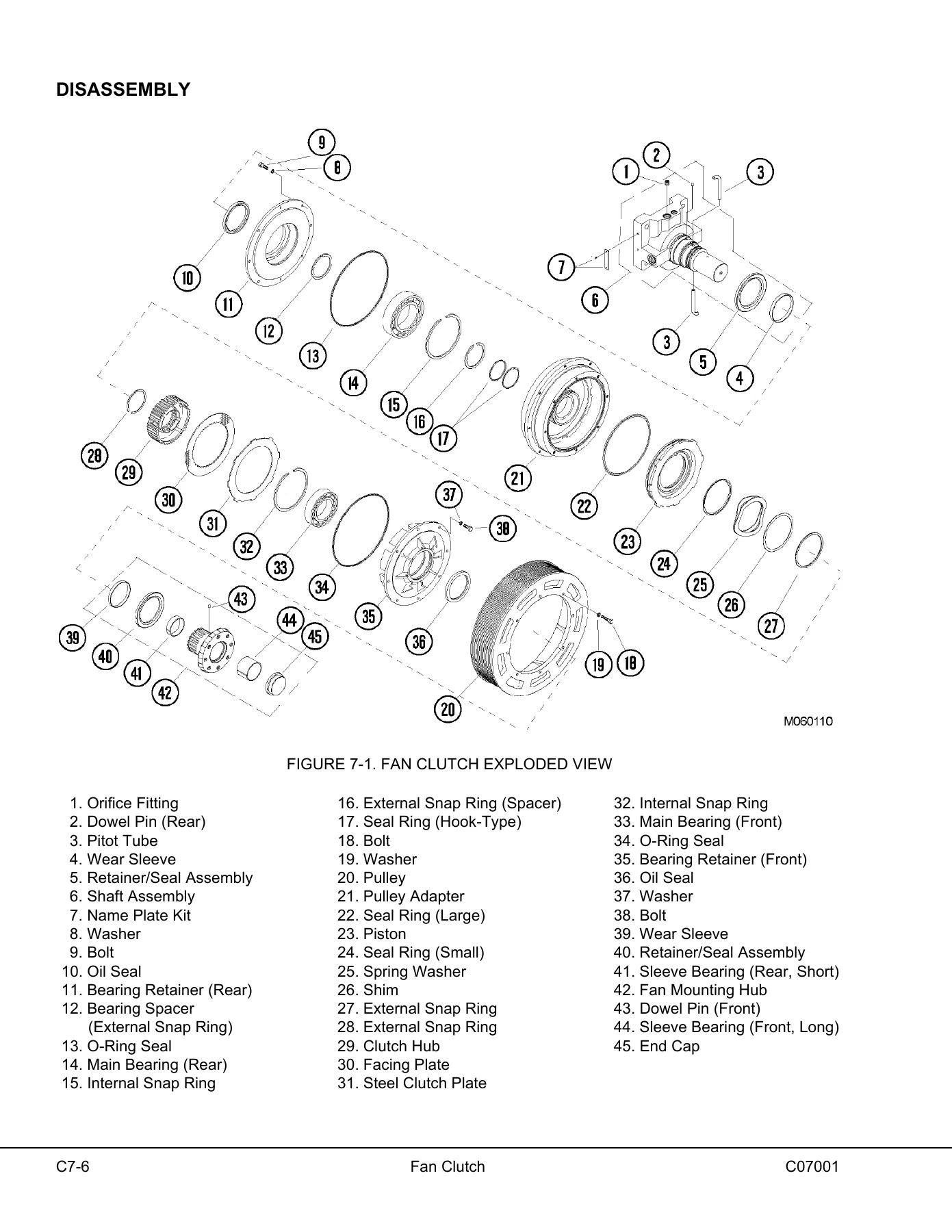
This major section begins with the Power Module, covering the radiator, engine, and alternator/blower assemblies mounted on the roll-out subframe. It provides detailed procedures for engine/alternator mating, including measuring procedures and shim determination. The Cooling System chapter covers radiator removal and installation, internal inspection, external cleaning, disassembly, assembly, and pressure testing. Power Train coverage includes alternator removal and engine removal and installation. Air Cleaners are covered with operation, servicing, filter element replacement, precleaner section cleaning, and intake troubleshooting. The Fan Clutch chapter provides tooling, disassembly, cleaning, inspection, assembly, and test procedures.
Section D — Electric System (24 VDC, Non-Propulsion)
This section covers the 24 VDC electric supply system, including batteries, battery box, battery control box, disconnect switches, auxiliary battery receptacles, isolator diode, engine start relay, and the 24VDC to 12VDC converter. The electric cranking motor system with prelube is detailed, including operation, pressure switch, check valve, and timer solenoid. Cranking motor troubleshooting, no-load test, disassembly, cleaning, inspection, armature servicing, field coil checks, solenoid checks, and assembly are provided. The Battery Charging Alternator section covers general information, terminal identification, specifications, wiring diagram, periodic maintenance, testing, regulator testing, bench testing, static testing, field coil tests, stator tests, thermal switch test, and alternator repair. VHMS components, software, checkout, and troubleshooting are also included.
Section E — Electric Propulsion and Control
This section covers the Electric Propulsion System Components, including the Propulsion System Controller (PSC), Truck Control Interface (TCI), Diagnostic Information Display (DID) panel, and DID panel event codes. PSC software functions, alternator field control, desired three-phase voltage, desired DC link voltage, self-load, propel torque control, retard torque control, wheel slide control, resistor grid control, chopper voltage control, event detection and processing, event restrictions, event logging and storage, serial data communications, output processing, abnormal conditions, and overriding functions are all documented. Electronic accelerator and retard pedals are covered with removal, installation, disassembly, and assembly. The AC Drive System Electrical Checkout Procedure includes normal truck shutdown, shutdown after system failure, system checkout, battery and control circuit checks, CPU battery checks, memory backup battery replacement, TCI programming, PSC programming, inverter programming, CPU reset, PSC checkout, TCI checkout, calibrations, erasing events, gate driver power converter test, load testing, troubleshooting, and phase module replacement.
Section G — Drive Axle, Spindles and Wheels
This section covers Tires and Rims, including front and rear tire and rim removal and installation, rim and tire preparation, lubricants, and tire installation. The Front Wheel Hub and Spindle Assembly chapter provides removal, spindle pusher tool usage, installation, disassembly, cleaning and inspection, assembly, and wheel bearing adjustment. Oil sampling procedure and oil drain and refill procedures are included. Steering cylinders and tie rod removal, installation, and bearing replacement are documented. Toe-in adjustment is also covered. The Rear Axle Housing Attachment chapter includes pivot pin removal and installation, pivot eye bearing disassembly and assembly, pivot eye repair, and anti-sway bar removal, installation, disassembly, cleaning, inspection, and assembly. The Rear Axle Housing chapter covers removal, installation, wheel motor removal, cleaning and inspection, and installation.
Section H — HYDRAIR® II Suspensions
This section covers the front and rear HYDRAIR® II suspensions, which are hydro-pneumatic components containing oil and nitrogen gas. Front suspension removal, installation, minor repair (lower bearing structure and seals), major suspension rebuild, and pressure test are documented. Rear suspension removal, installation, disassembly, cleaning and inspection, assembly, and pressure test are covered. The Oiling and Charging Procedures section includes general information, equipment list, HYDRAIR® charging kit, support blocks for oiling and charging dimensions, front suspension oiling, front suspension nitrogen charging, rear suspension oiling, rear suspension nitrogen charging, and oil and nitrogen specifications chart.
Section J — Brake Circuit
This section covers the hydraulic brake circuit, including service brake circuit operation, secondary braking and automatic apply, parking brake circuit, brake lock circuit, and warning circuit. Brake circuit component service includes the brake valve, hydraulic brake accumulators, and brake manifold. The Brake Circuit Check-Out Procedure provides equipment required, initial system set-up, parking brake checks, brake system check-out, brake lock checks, failure modes check-out, and troubleshooting. Wheel Speed Front Disc Brakes (Rockwell) are covered with caliper removal, installation, disassembly, assembly, cleaning and inspection, brake lining replacement, front service brake conditioning (burnishing) procedure, and brake bleeding procedures. Armature Speed Rear Disc Brakes are covered with caliper and disc removal, installation, adjustment, caliper disassembly, piston subassembly, preparation for assembly, inspection, piston assembly return spring force and built-in clearance (BIC), assembly, periodic inspections, brake lining replacement, brake disc inspection, service brake conditioning (burnishing) procedure, and brake bleeding procedure.
Section L — Hydraulic System
This section covers the hydraulic system operation and component description, including hoist pump, steering/brake pump, tank, high pressure hydraulic filters, bleeddown manifold, steering system accumulators, and disabled truck connectors. Hydraulic component repair covers hoist pump removal, installation, disassembly, inspection, and assembly. Hydraulic tank filling instructions, removal, installation, strainers, breathers, hoist circuit filters, filter element replacement, and indicator switch are documented. The Steering Circuit chapter includes steering circuit operation, component description, steering control unit, flow amplifier, bleed down manifold, accumulators, high pressure filter, steering/brake pump, and principle of operation. Steering circuit component repair covers bleed down manifold, accumulator, flow amplifier, steering control unit, steering cylinder, steering circuit filter, and steering and brake pump. The Hoist Circuit chapter includes hoist circuit operation and component description, hoist valve, hoist pilot valve, hoist-up limit solenoid, pilot operated check valve, and counterbalance valve manifold. Hoist system operation modes are detailed with float position, power up, hold, power down, and float operation. Hoist circuit component repair covers hoist valve, hoist pilot valve, body up limit solenoid, pilot operated check valve, hoist cylinders, counterbalance manifold, and disabled truck dumping procedure. Hydraulic checkout procedures include steering and brake pump pressure check and adjustment, bleeddown manifold, shock and suction valves, leakage tests, accumulator bleed down procedure, low steering pressure switch, checking hoist system pressures, hoist counterbalance valve, hydraulic system flushing procedure, and oil cleanliness check.
Section M — Options and Special Tools
This section covers optional equipment including the ANSUL Fire Control System, Engine Coolant Heater, Radiator Shutters, Payload Meter III, and Reserve Engine Oil System. The Special Tool Group chapter lists nitrogen charging valve, roll-out assembly, eye bolt, offset wrench, torque adapter, handle, seal installer, sleeve alignment tools, quick disconnect coupling, harness, tube, belt tension tester, belt alignment tool, sockets and adapters, payload data manager, and miscellaneous service tools. Payload Meter III coverage includes operation, component description, operator’s display and switch, payload operation and calculation, sources for payload error, haul cycle data, PC software overview, downloading data, PLM III system configuration, data analysis, troubleshooting, and PLMIII check out procedure. Reserve Engine Oil System includes operation, LED monitor light, tank fill control, filling procedure, service, troubleshooting, and system electrical schematics.
Section N — Operator’s Cab
This section covers the truck cab and components, cab door removal, installation, adjustment, door jamb bolt adjustment, door handle plunger adjustment, door glass replacement, door window regulator replacement, door handle or latch assembly replacement, door and door hinge seal replacement, door opening seal removal and installation, glass replacement (adhesive-bonded windows), and windshield and rear glass removal and installation. Cab components coverage includes windshield wipers, wiper motor, wiper arm, wiper linkage, and windshield washer. Operator seat adjustment, removal, and installation are documented. Operator Comfort covers the heater/air conditioner operation, components, circuit breakers, relays, heater core, fan motor and speed control, actuators, cab air filter, environmental impact of air conditioning, air conditioning for off-highway vehicles, principles of refrigeration, air conditioner system components, electrical circuit, thermostat, compressor clutch, Trinary™ switch, system servicing, service tools and equipment, system performance test, system oil, refrigerant, system leak testing, recovering and recycling the refrigerant, system repair, A/C drive belt checkout procedure, component replacement, evacuating the system, charging the A/C system, troubleshooting, and preventive maintenance schedule. Operator cab controls coverage includes steering wheel and controls, steering column, pedals, grade/speed retard chart, overhead panel and displays, center console, diagnostic ports, heater/air conditioner compartment and controls, instrument panel, overhead status/warning indicators, VHMS, fuse blocks, and circuit breakers.
Section P — Lubrication and Service
This section covers service capacities, hydraulic tank service, wheel motor service, coolant level check, radiator filling procedure, reserve engine oil system, lubrication chart, 10 hour (daily) inspection, 50 hour lubrication and maintenance checks, 100 hour lubrication and maintenance checks, 250 hour lubrication and maintenance checks, 500 hour lubrication and maintenance checks, 1000 hour lubrication and maintenance checks, 2500 hour maintenance checks, 5000 hour maintenance checks, and 10,000 hour maintenance checks. The Automatic Lubrication System chapter includes general description, system components, filter, hydraulic motor and pump, grease reservoir, pressure reducing valve, flow control valve, solenoid valve, vent valve, lubrication cycle timer, pump cutoff pressure switch, grease pressure failure switch, pressure gauge, injectors, system operation, normal operation, system priming, filter assembly, lubricant pump, pump housing oil level, pump pressure control, pressure control valve adjustment, injectors (SL-1 Series H), injector specifications, injector adjustment, injector operation, system checkout, lubrication controller check, lubrication controller operation, lubrication controller components, lubrication controller adjustment, system troubleshooting chart, and preventive maintenance procedures.
Section Q — Alphabetical Index
A comprehensive alphabetical index is provided for quick reference to all topics covered throughout the manual.
Section R — System Schematics
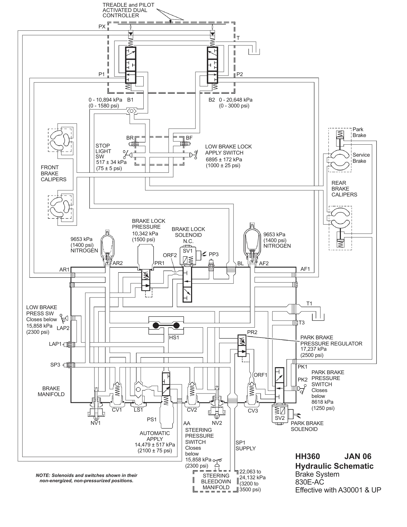
This section contains the hydraulic brake schematic (HH360), hydraulic schematic (HH361), and the complete 830E-AC electrical schematic (XS3200) broken into 35 sheets covering the GE system block diagram, main propulsion schematic, GE 24/15V power distribution, G.E. inverter firing, engine I/O, G.E./24V digital I/O, control panel analog inputs, 24V power distribution and circuit protection, operator cab overhead warning lights, auto lube system with warning, operator cab gauges and option switches, heater and air conditioner controls, work lights and horn, retard lights, backup lights and horns, operator drive system controls, radio, windows and wiper control, turn signal and clearance lights, fog lights and head lights, operator cab instrument lights, key switch and 5-minute idle, QSK-60 start circuit, engine circuits, payload meter 3 circuits, diagnostic ports and dispatch system, park brake and GE I/O, windshield wiper and turn signal controls, VHMS interface and Orbcomm modules, battery box, circuit locator sheet, and component locator sheet.
Why This Komatsu 830E-AC Shop Manual Matters
Whether you are performing routine maintenance, diagnosing a fault in the AC drive system, rebuilding a hoist cylinder, or adjusting the HYDRAIR® II suspension, this manual gives you the exact procedures, torque values, and specifications Komatsu specifies for the 830E-AC. It is the same reference used by professional service technicians in the field. With 1085 pages of detailed information, this manual covers every major system on the truck — from the SDA16V160 engine and the General Electric GTA-41 alternator to the electric propulsion inverters, wheel motors, hydraulic circuits, and structural components.
The manual is written specifically for the 830E-AC with serial numbers A30001 & Up, so you can be confident that the procedures and specifications apply directly to your truck. Safety notices, warnings, and cautions are integrated throughout, helping you work safely around high-voltage propulsion components, pressurized hydraulic systems, and heavy structures.
IMAGES PREVIEW
Instant PDF Delivery – No Shipping, No Waiting
This Komatsu 830E-AC shop manual PDF is available for immediate download after payment. There is no physical book to ship, no waiting for delivery, and no risk of a damaged or lost package. The PDF format works on any device — laptop, desktop, tablet, or smartphone — and you can print any page or section you need for use in the shop. Whether you are a single owner-operator or a service manager maintaining a fleet of 830E-AC trucks, this manual gives you the complete, searchable, and printable reference you need to keep your equipment running safely and efficiently.
Don’t rely on guesswork or generic repair advice. Get the Komatsu 830E-AC Dump Truck Shop Manual CEBM016202 today and have the complete factory service information at your fingertips.

Reviews
There are no reviews yet.