Komatsu 830E Dump Truck Shop Manual SN A30662, A30677-A30688 – PDF DOWNLOAD
Original price was: $63.95.$26.95Current price is: $26.95.
Komatsu 830E Dump Truck Shop Manual
Book Code: CEBM008900
SERIAL NUMBERS A30662, A30677-A30688
Description
Komatsu 830E Dump Truck Shop Manual
FILE DETAILS:
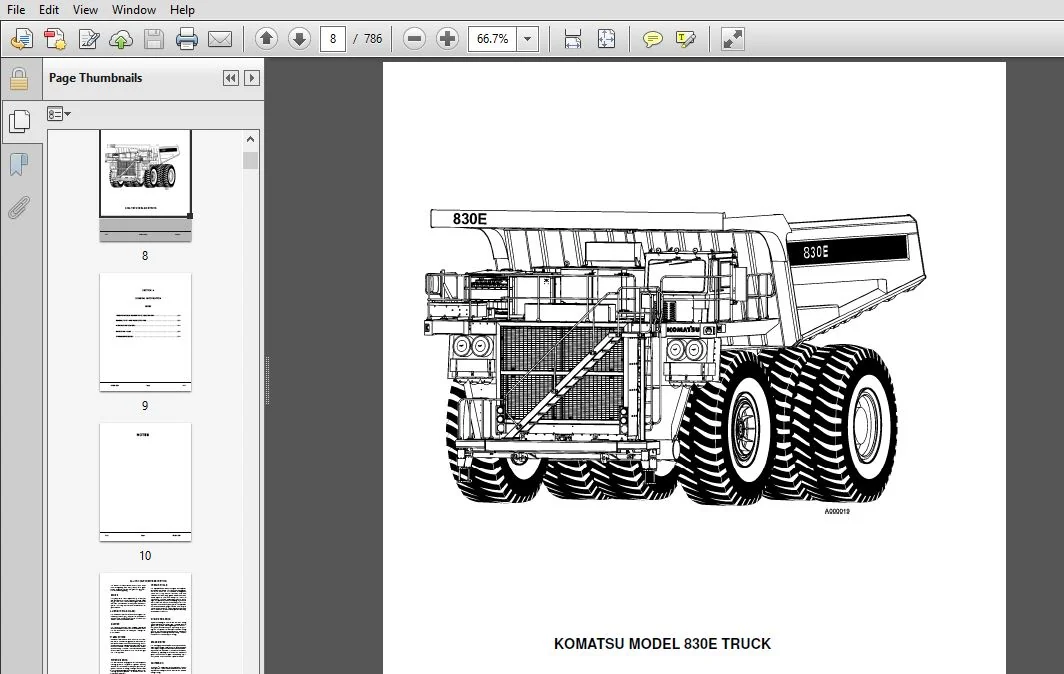
Komatsu 830E Dump Truck Shop Manual
Brands: Komatsu
Equipment Type: Dump Truck
Manuals Type: Shop Manual
Machine Model: 830E
Serial Number: A30662, A30677-A30688
Book Code: CEBM008900
Language: English
Pages:786
File Format: Portable Document Format (PDF)
KOMATSU 830E DUMP TRUCK SHOP MANUAL SN A30662, A30677-A30688 – PDF DOWNLOAD:
IMAGES PREVIEW OF THE MANUAL:
DESCRIPTION:
Komatsu 830E Dump Truck Shop Manual
FOREWORD:
This Shop Manual is written for use by the service technician and is designed to help the technician become fully knowledgeable of the truck and all its systems in order to keep it running and in production. All maintenance personnel should read and understand the materials in this manual before performing maintenance and/or operational checks on the truck. All safety notices, warnings and cautions should be understood and followed when accomplishing repairs on the truck.
- The first section covers component descriptions, truck specifications and safe work practices, as well as other general information. The major portion of the manual pertains to disassembly, service and reassembly. Each major serviceable area is dealt with individually. For example: The disassembly, service and reassembly of the radiator group is discussed as a unit. The same is true of the engine and engine accessories, and so on through the entire mechanical detail of the truck.
- Disassembly should be carried only as far as necessary to accomplish needed repairs. The illustrations used in this manual are, at times, typical of the component shown and may not necessarily depict a specific model. This manual shows dimensioning of U.S. standard and metric (SI) units throughout and all references to “Right”, “Left”, “Front”, or “Rear” are made with respect to the operator’s normal seated position, unless specifically stated otherwise.
- Standard torque requirements are shown in torque charts in the general information section and individual torques are provided in the text in bold face type, such as 100 ft.lbs. (135 N.m) torque. All torque specifications have ±10% tolerance unless otherwise specified.
- A Product Identification plate is normally located on the truck frame in front of the right side front wheel and designates the Truck Model Number, Product Identification Number (vehicle serial number), and Maximum G.V.W. (Gross Vehicle Weight) rating. The KOMATSU Truck Model designation consists of three numbers and one letter (i.e. 830E). The three numbers represent the basic truck model.
- The letter “E” designates an Electrical propulsion system. The Product Identification Number (vehicle serial number) contains information which will identify the original manufacturing bill of material for this unit. This complete number will be necessary for proper ordering of many service parts and/or warranty consideration.
TABLE OF CONTENTS:
Komatsu 830E Dump Truck Shop Manual
MAIN MENU.................................................................................. 0
FOREWORD................................................................................... 5
CONTENTS................................................................................... 7
GENERAL INFORMATION........................................................................ 9
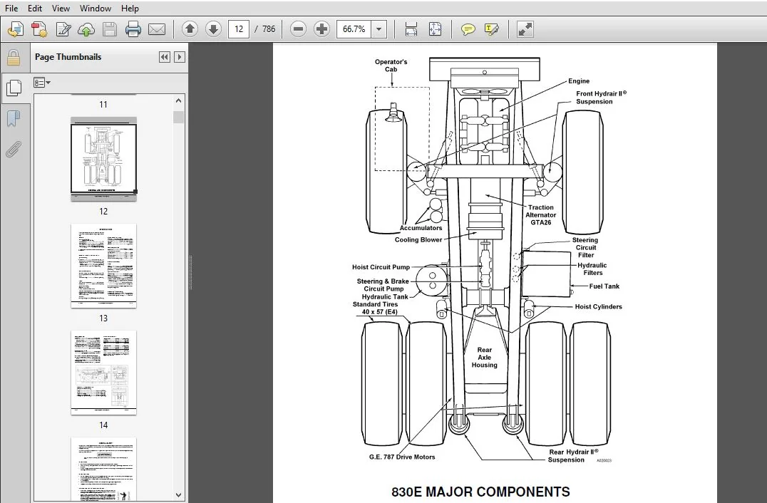
Truck Component Description and Specifications......................................... 11
General Safety and Truck Operation..................................................... 15
Precautions During Operation....................................................... 19
Battery............................................................................ 24
Precautions For Maintenance........................................................ 25
During Maintenance................................................................. 26
Tires.............................................................................. 29
Additional Job Site Rules.......................................................... 30
When Repairs Are Necessary......................................................... 31
Operating Instructions............................................................. 33
Warnings and Cautions.................................................................. 47
Charts and Tables...................................................................... 55
Storage Procedures..................................................................... 61
Short Term Idle Periods............................................................ 61
Preparation for Storage............................................................ 62
Removal from Storage............................................................... 63
Reconditioning an Idle Vehicle..................................................... 65
Engine Operation................................................................... 68
After Engine Has Started........................................................... 69
Engine Storage-Cummins............................................................. 70
Engine Storage (Short Term).................................................... 70
Engine Storage (Long Term)..................................................... 71
Engine Storage- Detroit Diesel..................................................... 72
Preparing for Storage.......................................................... 72
Temporary Storage (30 Days or Less)............................................ 72
Extended Storage (More than 30 Days)........................................... 72
Procedure for Restoring an Engine to Service Which Has Been in Extended Storage.... 74
Electric Drive Trucks.............................................................. 75
Preservation and Storage- Allison Transmission..................................... 79
STRUCTURES................................................................................. 81
Structural Components.................................................................. 83
Ladders............................................................................ 83
Right Hand Deck.................................................................... 84
Removal........................................................................ 84
Installation................................................................... 84
Center and Left Hand Deck Components............................................... 85
Fuel Tank.......................................................................... 86
Removal........................................................................ 86
Installation................................................................... 86
Dump Body.............................................................................. 87
Removal............................................................................ 87
Installation....................................................................... 88
Body Pads.......................................................................... 89
Adjustment..................................................................... 90
Body Guide......................................................................... 90
Body-Up Retention Cable............................................................ 90
Body Position Indicator............................................................ 91
Rock Ejectors...................................................................... 91
Inspection..................................................................... 91
Hoist Limit Switch................................................................. 91
Body Up Switch..................................................................... 91
ENGINE..................................................................................... 93
Power Module........................................................................... 95
Preparation........................................................................ 95
Removal........................................................................ 95
Installation................................................................... 99
Cooling System.........................................................................101
Cooling System Description.........................................................101
Radiator...........................................................................102
Removal........................................................................102
Installation...................................................................104
Radiator Filling Procedure.........................................................104
Power Train............................................................................105
Alternator Removal Procedure.......................................................105
Engine Alternator Mating.......................................................107
Measuring Procedure............................................................107
Joining Alternator and Engine..................................................109
Engine.............................................................................110
Removal........................................................................110
Installation...................................................................110
Air Filtration System..................................................................111
Air Cleaner........................................................................111
Operation......................................................................111
General Service Information....................................................111
Main Filter Element................................................................111
Safety Filter Element..............................................................112
Air Intake Troubleshooting.....................................................113
Air Cleaner Assembly Cleaning......................................................113
Main Filter Cleaning...........................................................113
Precleaner Section Cleaning....................................................114
ELECTRICAL SYSTEM (24VDC NON-PROPULSION)...................................................117
24VDC Electric Supply System...........................................................119
Electrical System Description......................................................119
Battery- Maintenance and Service...................................................119
Troubleshooting................................................................119
Battery Charging System (Niehoff)..................................................121
General Description............................................................121
Troubleshooting Procedures.....................................................121
On Vehicle Troubleshooting Guide- Self Energized Alternator....................124
Advanced System Troubleshooting................................................126
24VDC Electric Starter System (with Prelube).......................................128
Operation......................................................................128
Maintenance....................................................................129
Troubleshooting................................................................130
24VDC Electric Start System........................................................132
Troubleshooting................................................................133
24VDC Electrical System Components.....................................................141
Passenger Seat Base Compartment....................................................141
Components.........................................................................141
Alarm Indicating Device............................................................144
Battery Equalizer..................................................................146
Body-Up Switch.....................................................................147
Hoist Limit Switch.................................................................147
24Volt Relay and Diode Boards......................................................148
Circuit Breaker Chart..............................................................154
ELECTRICAL PROPULSION COMPONENTS...........................................................155
Electrical Propulsion Components.......................................................157
General System Description.........................................................157
Control System.....................................................................157
FL275 Panel........................................................................159
Card Replacement...............................................................160
Card Repair....................................................................160
Computer Description...........................................................161
Software.......................................................................161
2-Digit Display Panel..............................................................164
Events.........................................................................164
Frames.........................................................................165
Windows........................................................................165
2 Digit Display Panel Codes (Table I)..........................................167
Subcode Descriptions (Table II)................................................174
Portable Test Unit (PTU)...........................................................177
Description....................................................................177
Software Installation Preparation..............................................178
The Main Menu..............................................................180
PTU Software Menu Tree.....................................................181
Configuration (CFG) File Conversion........................................182
Statex Configuration Files.....................................................186
Programming The Truck..........................................................197
PTU Hookup.................................................................197
Download Configuration Files...............................................199
Event Data.....................................................................201
Statistical Data...............................................................203
Statistical Data Codes- Counters (Table III)...................................204
Statistical Data Codes- Profiles (Table IV)....................................210
Truck Specific Information.....................................................214
Temporary Truck Settings.......................................................215
Miscellaneous Software Features................................................216
Saving Data................................................................216
PTU Abbreviations..........................................................217
Other Menu Selections......................................................217
Miscellaneous Electrical Propulsion Components.....................................218
Alternator.....................................................................218
Electric Wheel Motors..........................................................218
Electronic Accelerator and Retard Control......................................218
Cooling Blower Warning System..................................................220
Electrical Control Cabinet.....................................................221
Statex III Electric Drive Components Abbreviations.................................226
Statex III Electrical System Checkout Procedure........................................229
General Information................................................................231
Communications Port Check..........................................................232
PTU Hookup.....................................................................232
1.0 Sequence Tests.................................................................234
Throttle System Check and Adjustment...........................................235
Electronic Throttle System.................................................235
Electronic Throttle System fuel Enhancement ("Fuel Saver").................236
Retard System Check and Adjustment- Electronic Pedal System....................238
Williams Electronic Retard Pedal and ACC/RET or RET Interface..............238
Electronic Retard Pedal, Current Production Trucks.........................239
Reverser and Propulsion Contractors Check......................................241
Propulsion Lockout Test (DDEC&MTU Engine Trucks Only)..........................242
Retard Contractors Operation Check.............................................243
Ground Fault Sensing Check.....................................................243
Ground Fault in Retard Operation Check.........................................243
Override Operation Check.......................................................244
Anti-Reversal Function (AR) Check..............................................245
Overspeed Retard Operation Check...............................................245
Hoist Interlock Operation Check................................................246
Motor Blower Fault Light Operation Check.......................................247
Digital Input/Output Signals Tests- FL275 Card Panel...............................248
Setup Manual Digital Input/Output Test on PTU..................................248
Digital Input Checks...........................................................249
Digital Output Checks..........................................................251
Analog Input Signals Test- FL275 Card Panel........................................254
Setup Analog Input Monitor Screen on PTU.......................................254
Analog Input Checks............................................................255
Frequency Input Checks.........................................................262
Speed Event Checks.................................................................264
Single Speed Overspeed-Overspeed Settings Check................................265
Empty Truck- 2 Speed Overspeed Settings Check..................................265
Loaded Truck- 2 Speed Overspeed Settings Check.................................265
Other Speed Events Checks......................................................265
Retard Speed Control System Check..................................................267
Overspeed Pickup and Dropout Check.............................................267
Retard Pot Maximum Setting Check...............................................268
Retard Pot Minimum Setting Check...............................................268
Accelerator Pedal Override of Retard Speed Control.............................268
Load Test Using Truck Retard Grids.................................................269
Load Test......................................................................270
Motor Field current Check in Retarding.............................................271
Retard Check...................................................................271
Miscellaneous Component Test and Adjustment........................................272
Brake System Interlocks Check..................................................272
Blower Loss Pressure Switch Adjustment.........................................273
SYNC Transformer Checkout......................................................273
Power Contactor Position Sensor Adjustment.....................................273
Battery Boost Adjustment.......................................................274
Isolation Amplifier& Voltage Module Test.......................................274
Voltage Measuring Module Test (VMM1&VMM2)..................................274
ISO-AMP Test...............................................................275
Motor Rotation Test............................................................275
Ground Fault Checks............................................................276
Optional Payload Meter (PLM II) Check-Out Procedure................................277
Check the Deck Mounted Lights..................................................277
Check Pressure Sensors.........................................................277
Check Operation of Data Storage Trigger Module.................................277
Zero the Angle Sensor..........................................................277
Check Body-Up Switch Function..................................................277
Miscellaneous Charts...............................................................278
Wheel Motor Gear Ratios........................................................278
Maximum Allowable Truck Speeds.................................................279
Engine Options.................................................................280
DRIVE AXLE, SPINDLE AND WHEELS.............................................................281
Tires and Rims.........................................................................283
Front Tires and Rims...............................................................283
Removal........................................................................283
Installation...................................................................284
Rear Tires and Rims................................................................285
Removal........................................................................285
Installation...................................................................286
Rim................................................................................287
Tire Removal...................................................................287
Rim and Tire Preparation.......................................................287
Lubricants.....................................................................288
Tire Installation..............................................................288
Front Wheel Hub and Spindle............................................................291
Wheel Hub and Spindle Assembly.....................................................291
Removal........................................................................291
Spindle Pusher Tool Usage......................................................292
Installation...................................................................293
Disassembly....................................................................295
Cleaning and Inspection........................................................295
Assembly.......................................................................296
Wheel Bearing Adjustment.......................................................298
Wheel Bearing Adjustment (Tire Mounted)........................................298
Steering Cylinders and Tie Rod.....................................................300
Spherical Bearing Wear Limits..................................................300
Removal........................................................................301
Installation...................................................................301
Bearing Replacement............................................................301
Toe-In Adjustment..................................................................303
Rear Axle Housing Attachment...........................................................305
Pivot Pin..........................................................................305
Removal........................................................................305
Installation...................................................................305
Pivot Eye Bearing..................................................................306
Disassembly....................................................................306
Assembly.......................................................................306
Pivot Eye Repair...................................................................307
Removal........................................................................307
Disassembly....................................................................307
Assembly.......................................................................307
Installation...................................................................307
Anti-Sway Bar......................................................................308
Removal........................................................................308
Installation...................................................................308
Disassembly....................................................................308
Cleaning and Inspection........................................................308
Assembly.......................................................................308
Rear Axle Housing......................................................................309
Rear Axle Housing..................................................................309
Removal........................................................................309
Installation...................................................................309
Wheel Motor........................................................................309
Removal........................................................................309
Cleaning and Inspection........................................................310
Installation...................................................................310
HYDRAIR II SUSPENSIONS.....................................................................311
Front Suspension.......................................................................313
Removal............................................................................313
Installation.......................................................................314
"Turn of the Nut" Tightening Procedure.........................................316
Minor Repair.......................................................................317
Bearing Structure Removal......................................................317
Bearing Structure Installation.................................................317
Major Suspension Rebuild...........................................................318
Disassembly....................................................................318
Assembly.......................................................................319
Pressure Test..................................................................320
Rear Suspension........................................................................321
Removal............................................................................321
Installation.......................................................................323
Disassembly........................................................................325
Cleaning and Inspection............................................................325
Assembly...........................................................................325
Pressure Test......................................................................326
Oiling and Charging Procedure..........................................................327
General............................................................................327
Equipment List.....................................................................327
Front Suspension...................................................................329
Front Suspension Oiling........................................................329
Front Suspension Nitrogen Charging.............................................330
Rear Suspension....................................................................331
Rear Suspension Oiling.........................................................331
Rear Suspension Nitrogen Charging..............................................332
Oil and Nitrogen Specifications Chart..............................................334
BRAKE CIRCUIT..............................................................................335
Brake Circuit..........................................................................337
Service Brake Circuit Operation....................................................337
Secondary Braking and Automatic Apply..............................................339
Parking Brake Circuit..............................................................339
Brake Lock Circuit.................................................................340
Warning Circuit....................................................................340
Brake Circuit Component Service........................................................343
Brake Valve........................................................................343
Removal........................................................................343
Installation...................................................................345
Disassembly....................................................................346
Cleaning and Inspection........................................................348
Assembly.......................................................................348
Differential Pressure Switch.......................................................351
Disassembly....................................................................351
Cleaning and Inspection........................................................351
Assembly.......................................................................351
Valve Bench Test and Adjustment....................................................352
Test Set Up Procedure..........................................................353
Differential Pressure Switch Test..............................................353
Final Test and Adjustment......................................................354
Installation of Brake Pedal Actuator Assembly to Brake Valve.......................355
Brake Valves with Integral Mounted Electronic Retard Pedal.........................356
Hydraulic Brake Accumulators.......................................................357
Removal........................................................................357
Installation...................................................................357
Disassembly....................................................................357
Cleaning and Inspection........................................................358
Assembly.......................................................................359
Brake Circuit Check-Out Procedure......................................................361
Equipment Required.................................................................363
Initial System Set-Up..............................................................364
Parking Brake......................................................................364
Brake System Check-Out.............................................................364
Failure Modes Check-Out............................................................365
Brake Circuit and Brake Valve Troubleshooting......................................367
Hydraulic Brake System Check-Out Procedure Data Sheet..............................371
Rockwell Wheel Speed Front Disc Brakes.................................................373
Brake Caliper......................................................................373
Brake Lining.......................................................................377
Front Service Brake Conditioning (Burnishing) Procedure............................378
Brake Bleeding Procedures..........................................................379
Rockwell Armature Speed Rear Disc Brakes...............................................381
Rear Brakes........................................................................381
Caliper, Disc and Parking Brake....................................................381
Caliper Piston.....................................................................386
Bench Test.........................................................................392
Brake Lining.......................................................................393
Service Brake Conditioning (Burnishing) Procedure..................................396
Brake Bleeding Procedure...........................................................398
Rockwell Disc Parking Brake............................................................399
Park Brake Caliper.................................................................399
Removal........................................................................399
Installation...................................................................400
Parking Brake Adjustment.......................................................400
Park Brake Caliper Disassembly.................................................402
Cleaning and Inspection........................................................402
Park Brake Caliper Assembly....................................................403
Park Brake Lining Replacement......................................................404
Park Brake Burnish Procedure.......................................................404
Brake Bleeding Procedure...........................................................404
HYDRAULIC SYSTEM...........................................................................405
Hydraulic System.......................................................................407
Component Description..............................................................408
Hydraulic System Component Repair......................................................411
Hoist Pump.........................................................................411
Hydraulic Tank.....................................................................422
Hydraulic Tank Strainers.......................................................423
Hydraulic Tank Breathers.......................................................424
Hoist Circuit Filters..........................................................424
Filter Element Replacement.....................................................425
Steering Circuit.......................................................................427
Steering Circuit Operation.........................................................427
Component Description..............................................................428
Steering Control Unit..........................................................428
Flow Amplifier.................................................................428
Bleed Down Manifold............................................................438
Accumulators...................................................................439
High Pressure Filter...........................................................439
Steering/ Brake Pump...........................................................439
Operation......................................................................440
Steering Circuit Component Repair......................................................445
Bleed Down Manifold................................................................445
Accumulator........................................................................446
Steering Accumulator Charging Procedure........................................450
Flow Amplifier.....................................................................451
Steering Control Unit..............................................................456
Steering Cylinder..................................................................462
Steering Circuit Filter............................................................463
Steering and Brake Pump............................................................465
Hoist Circuit..........................................................................477
Hoist Circuit Operation............................................................477
Component Description..............................................................478
Hydraulic Tank.................................................................478
Hoist Pump.....................................................................478
High Pressure Filters..........................................................478
Hoist Valve....................................................................479
Hoist Pilot Valve..............................................................480
Hoist Up Limit Solenoid........................................................480
Pilot Operated Check Valve.....................................................480
Counterbalance Valve Manifold..................................................480
Hoist System Operation Modes.......................................................481
Hoist Circuit Component Repair.........................................................493
Hoist Valve........................................................................493
Inlet Section..................................................................494
Spool Section..................................................................496
Hoist Pilot Valve..................................................................499
Body Up Limit Solenoid.............................................................502
Pilot Operated Check Valve.........................................................502
Hoist Cylinders....................................................................502
Counterbalance Manifold............................................................510
Disabled Truck Dumping Procedure...................................................511
Hydraulic Checkout Procedure...........................................................513
Steering and Brake Pump............................................................513
Bleed Down Manifold................................................................514
Shock and Suction Valves...........................................................515
Leakage Tests......................................................................516
Troubleshooting Chart..............................................................518
Steering Circuit...............................................................518
Steering Pump..................................................................520
Flow Amplifier.................................................................522
Checking Hoist System Pressures....................................................524
Hoist Counterbalance Valve Adjustment..............................................526
Troubleshooting Guide (Hoist Pump).................................................528
Hydraulic System Flushing Procedure................................................530
OPTIONS AND SPECIAL TOOLS..................................................................531
Ansulfire Control System Manual........................................................533
Operation..........................................................................533
Inspection and Maintenance.........................................................533
Recharging Procedures..............................................................534
Alternator and Wheelmotor Cooling Air Filter System....................................535
System Adjustment..................................................................535
Pump...............................................................................535
Blower Drive Motor.................................................................538
Blower Bearing Repair..............................................................541
Air Cleaner........................................................................542
Wiggins Quick Fill Fuel System.........................................................543
Fuel Receiver......................................................................543
Tank Breather Valve................................................................544
Buckeye Quick Fill Fuel System.........................................................547
Tank Breather Valve................................................................547
Fuel Receiver......................................................................548
Engine Coolant Heater..................................................................549
Heating Element....................................................................549
Thermostat.........................................................................550
Special Tools..........................................................................551
Air Conditioning System................................................................557
Environmental Impact...............................................................557
Operator Cab Air Conditioning......................................................558
Principles of Refrigeration........................................................558
Air Conditioner System Components..................................................560
Electrical Circuit.................................................................562
System Servicing...................................................................564
Service Tools and Equipment........................................................567
Manifold Gauge Set.................................................................569
System Performance Test............................................................572
System Leak Testing................................................................573
System Repair......................................................................574
Evacuating the System..............................................................581
Troubleshooting....................................................................583
Preventive Maintenance Schedule for A/C Systems....................................591
Radiator Shutters......................................................................593
Payload Meter III......................................................................597
Operation Section..................................................................600
Introduction.......................................................................600
Data Summary.......................................................................600
Data Gathering.....................................................................600
Component Description..............................................................601
System Diagram.................................................................601
Suspension Pressure Sensors....................................................601
Inclinometer...................................................................601
Operator Display...............................................................601
Operator Switch................................................................602
Speed Input....................................................................602
Body Up Switch.................................................................602
Brake Lock Switch..............................................................602
Payload Meter..................................................................602
Communications Ports...........................................................602
Kewswitch Input................................................................603
Payload Meter Power............................................................603
Load Lights....................................................................603
Wiring and Termination.........................................................604
TCI Outputs....................................................................604
Operator's Display and Switch......................................................605
Reading the Speedometer........................................................605
Reading the Load Display.......................................................605
Using the Operator ID..........................................................605
Using the Load and Ton Counter.................................................605
Total Ton Counter..............................................................605
Total Load Counter.............................................................606
Clearing the Counters..........................................................606
Viewing Live Sensor Data.......................................................606
Other Display Messages.........................................................606
Payload Operation & Calculation....................................................607
Description of Haul Cycle States...............................................607
States or Stages of a Typical Haul Cycle.......................................607
Haul Cycle Description.........................................................607
Load Calculation...............................................................608
Carry Back.....................................................................608
Measurement Accuracy...........................................................608
Sources for Payload Error......................................................608
Payload Error..............................................................608
Loading Conditions.........................................................609
Pressure Sensors...........................................................609
Swing Loads................................................................609
Speed and Distance.........................................................609
Haul Cycle Data....................................................................609
Haul Cycle Data................................................................610
Haul Cycle Warning Flags.......................................................611
Alarm Records..................................................................612
Frame Torque Data..............................................................612
Sprung Weight Data.............................................................613
Maximum Speed Data.............................................................613
PC Software Overview...............................................................613
PC Overview....................................................................613
System Configuration...........................................................613
Installing the PLM III Software................................................613
Downloading Data...................................................................614
PLM III System Configuration.......................................................615
Starting Communications........................................................615
Displayed Payload Units........................................................615
Time Units.....................................................................615
Connection Menu................................................................615
Connecting to the Payload Meter................................................616
Configure the Payload Meter....................................................616
Setting the Date and Time..................................................616
Setting the Truck Type.....................................................617
Setting the Gauge Display Units............................................617
Setting the Frame Serial Number............................................617
Setting the Truck Number...................................................617
Setting the Komatsu Customer...............................................617
Clean Truck Tare...............................................................618
Inclinometer Calibration.......................................................618
Data Analysis......................................................................619
Creating a Query...............................................................619
Sorting on Truck Type..........................................................619
Sorting on Date Range..........................................................620
Sorting on Time Range..........................................................620
Payload Detail Screen..........................................................621
Creating Reports...............................................................621
Summary - One Page Report......................................................622
Detailed - Multi Page Report...................................................622
Creating Graphs................................................................623
Exporting Data.................................................................623
CSV Export.....................................................................623
Compressed.....................................................................624
Importing Data.................................................................625
Deleting Haul Cycle Records....................................................625
Viewing Alarms.................................................................626
Deleting Alarm Records.........................................................626
Troubleshooting Section............................................................627
Troubleshooting................................................................627
Viewing Active Alarms..........................................................627
Real-Time Data Display.........................................................627
Testing the Payload Lights.....................................................627
Creating Log Files of Inputs...................................................628
Daily Inspections..............................................................628
Periodic Maintenance...........................................................628
Abnormal Displays at Power-Up..................................................629
No Payload Display When Key Switch is Turned ON................................630
No Display on Speedometer......................................................631
No Display on Operator Display.................................................631
No Communication With PC.......................................................632
Load Lights Don't Light During Loading.........................................633
Load Lights Remain ON..........................................................634
Load Lights Remain ON During Dumping...........................................634
Display Doesn't Clear When the Load is Dumped..................................634
Calibration Problems...........................................................635
Alarm 1-Left Front Pressure High...............................................636
Alarm 2-Left Front Pressure Low................................................636
Troubleshoot Wiring to Left Front Suspension...................................636
Alarm 3-Right Front Pressure High..............................................637
Alarm 4-Right Front Pressure Low...............................................637
Troubleshooting Wiring to Right Front Suspension...............................637
Alarm 5-Left Rear Pressure High................................................638
Alarm 6-Left Rear Pressure Low.................................................638
Troubleshooting Wiring to Left Rear Suspension.................................638
Alarm 7-Right Rear Pressure High...............................................639
Alarm 8-Right Rear Pressure Low................................................639
Troubleshoot Wiring to Right Rear Suspension...................................639
Alarm 9-Inclinometer High......................................................640
Alarm 10-Inclinometer Low......................................................640
Troubleshoot Inclinometer Wiring...............................................640
Alarm 13-Body Up Input Failure.................................................641
Alarm 15-Memory Write Failure..................................................642
Alarm 16 - Memory Read Failure.................................................642
Alarm 24 - System Key-On Status................................................642
Operator Switch Doesn't Work...................................................643
Alarm 26 - User Switch Fault - Select..........................................643
Alarm 27 - User Switch Fault - Set.............................................643
Connector Map..................................................................644
Connectors.....................................................................645
PLM III Check Out Procedure........................................................647
General Description............................................................647
Tools Required.................................................................647
Check Out Procedure............................................................647
PLM III Check Out Procedure Confirmation.......................................651
Flashburn Programming......................................................651
Confirmation Checklist.....................................................653
PLM III Components.................................................................654
Pressure Sensor................................................................654
Controller.....................................................................654
Speedometer....................................................................654
Reserve Engine Oil System..............................................................655
OPERATOR'S CAB.............................................................................661
Truck Cab..............................................................................663
Description........................................................................663
Removal............................................................................664
Installation.......................................................................665
Cab Door...........................................................................666
Removal........................................................................666
Installation...................................................................666
Door Adjustment................................................................666
Door Jam Bolt Adjustment.......................................................666
Door Handle Plunger Adjustment.................................................668
Replace Door Glass.............................................................669
Replace Door Window Regulator..................................................673
Replace Door Handle or Latch Assembly..........................................673
Door and Door Hinge Seal Replacement...........................................674
Glass Replacement..................................................................675
Adhesive Bonded Windows........................................................675
Windshield and Rear Glass......................................................676
Cab Components.........................................................................679
Windshield Wiper...................................................................679
Windshield Washer..................................................................681
Operator Comfort.......................................................................683
Operator Seat......................................................................683
Adjustment.....................................................................683
Heater/ Air Conditioner Controls...................................................684
Heater Components..............................................................685
Filter.........................................................................686
Operator Controls and Equipment........................................................689
Steering Wheel and Controls........................................................690
Steering Column................................................................690
Pedal Controls.....................................................................692
Overhead Controls, Gauges, Etc.....................................................693
Center Console.....................................................................694
Hoist Control Lever............................................................695
Instrument Panel and Indicator Lights..............................................698
Control Symbols................................................................698
Instrument Panel...................................................................699
Panel Gauges, Indicators and Controls..........................................700
Overhead Status / Warning Indicator Lights.........................................704
LUBRICATION AND SERVICE....................................................................711
Lubrication and Service................................................................713
Lubrication Specifications Charts..................................................713
Service Capacities.............................................................713
Hydraulic Tank Service and Filling Instructions................................713
Radiator Filling Procedure.....................................................714
Anti-Freeze Specifications.....................................................714
Reserve Engine Oil System......................................................714
Lubrication Chart- Oil and Grease Specifications...............................715
10 Hour (Daily) Lubrication and Maintenance Checks.................................716
50 Hour Lubrication and Maintenance Checks.........................................718
100 Hour Lubrication and Maintenance Checks........................................719
250 Lubrication and Maintenance Checks.............................................720
500 Hour Lubrication and Maintenance Checks........................................722
1000 Hour Lubrication and Maintenance Checks.......................................723
2500 Hour Lubrication and Maintenance Checks.......................................724
5000 Hour Lubrication and Maintenance Checks.......................................725
10,000 Hour Lubrication and Maintenance Checks.....................................725
Automatic Lubrication System...........................................................727
General Description................................................................727
System Components..................................................................729
System Operation...................................................................730
Injector Operation.............................................................732
General Instructions...............................................................733
System Checkout....................................................................736
Pump Rebuild...................................................................737
System Troubleshooting Chart...................................................740
Preventative Maintenance Procedures................................................743
Motorized Wheel Maintenance Schedule...................................................745
ALPHABETICAL INDEX.........................................................................749
SYSTEM SCHEMATICS..........................................................................753
HH353 HYDRAULIC SCHEMATIC..............................................................755
HH354 BRAKE SCHEMATIC..................................................................756
ES0600.................................................................................757
ES0601 INDEX AND SYMBOLS...........................................................757
ES0602 CIRCUIT NUMBER LOCATION.....................................................758
ES0603 COMPONENT LOCATOR...........................................................759
ES0604 COMPONENT LOCATOR...........................................................760
ES0605 G.E. FAULT CODES............................................................761
ES0606 G.E. FAULT CODES............................................................762
ES0607 POWER DISTRIBUTION - 24V....................................................763
ES0608 POWER 18 ELEMENT 3 STEP RETARDING...........................................764
ES0609 POWER 18 ELEMENT 3 STEP RETARDING...........................................765
ES0610 POWER 20 ELEMENT 7 STEP RETARDING...........................................766
ES0611 DRIVE SYSTEM CONTROL CIRCUITS...............................................767
ES0612 TWO DIGIT DISPLAY...........................................................768
ES0613 G.E. ANALOG INPUTS..........................................................769
ES0614 G.E. DIGITAL INPUTS, AUTO LUBE CONTROL......................................770
ES0615 REAR TAIL LIGHTS, DIMMER CONTROL............................................771
ES0616 5 MINUTE IDLE, SPARE WIRES..................................................772
ES0617 WINDOWS, RADIO, GAUGES......................................................773
ES0618 CONTACTOR FEEDBACK..........................................................774
ES0619 CONTACTOR COILS.............................................................775
ES0620 MACHINE CONTROL CIRCUITS....................................................776
ES0621 ACCELERATOR, RETARD PEDALS..................................................777
ES0622 HYDRAULIC CONTROLS, ALARMS..................................................778
ES0623 HEATER/AC, WINDSHIELD WIPER CONTROLS........................................779
ES0624 LIGHT CONTROL CIRCUITS......................................................780
ES0625 INSTRUMENT LIGHTS, DIAGNOSTIC PORTS.........................................781
ES0626 MOD. MINING DISPATCH........................................................782
ES0627 CUMMINS QSK60 ENGINE........................................................783
ES0628 CUMMINS QSK60 ENGINE........................................................784
ES0629 4000 DDEC ENGINE............................................................785
PLEASE NOTE:
- This is not a physical manual but a digital manual – meaning no physical copy will be couriered to you. The manual can be yours in the next 2 mins as once you make the payment, you will be directed to the download page IMMEDIATELY.
- This is the same manual used by the dealers inorder to diagnose your vehicle of its faults.
- Require some other service manual or have any queries: please WRITE to us at [email protected]


Kamryn Shane –