Trusted Business
Verified & Licensed
Virus Free Files
100% Safe Downloads
Secure Payment
SSL Protected
Instant Delivery
Available Immediately
Sale!


KOMATSU 860E-1KT DUMP TRUCK Operation & Maintenance Manual (SN:A30015 – A30030) KOMATSU 860E-1KT – PDF DOWNLOAD
Original price was: $81.95.$24.95Current price is: $24.95.
- KOMATSU 860E-1KT DUMP TRUCK Operation & Maintenance Manual
- SERIAL NUMBER:A30015 – A30030
- PUBLICATION NUMBER:CEAM022401
Instant PDF Download
Available immediately
Save to Your Device
Download & keep forever
Antivirus Scanned
100% virus-free
Trusted Worldwide
175,000+ customers
Description
KOMATSU 860E-1KT DUMP TRUCK Operation & Maintenance Manual (SN:A30015 – A30030) KOMATSU 860E-1KT
KOMATSU 860E-1KT DUMP TRUCK OPERATION & MAINTENANCE MANUAL (SN:A30015 – A30030) KOMATSU 860E-1KT – PDF DOWNLOAD:
IMAGE PREVIEW:
DESCRIPTION:
KOMATSU 860E-1KT DUMP TRUCK Operation & Maintenance Manual (SN:A30015 – A30030) KOMATSU 860E-1KT
- This manual is written for use by the operator and/or the service technician. It is designed to help these persons to become fully knowledgeable of the truck and all of its systems in order to keep it operating safely and efficiently. All operators and maintenance personnel should read and understand the information in this manual before operating the truck or performing maintenance and/or operational checks on the truck. All safety notices, warnings, and cautions should be understood and followed when operating the truck or performing repairs on the truck.
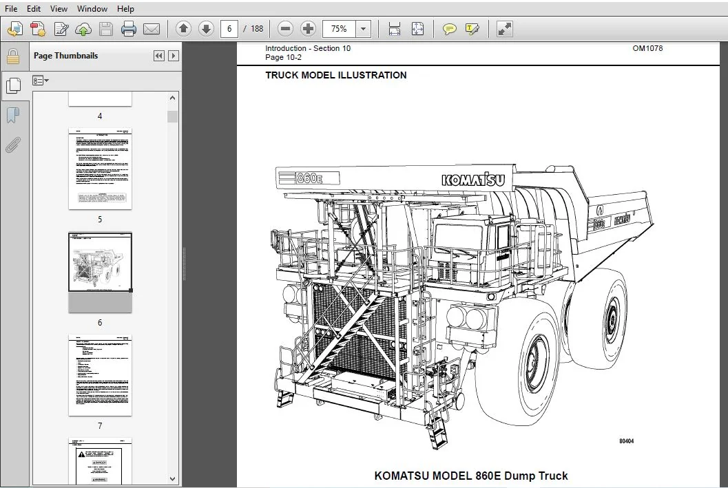
- A product identification plate is located on the frame in front of the right side front wheel. It designates the Truck Model Number, Product Identification Number (vehicle serial number), and Maximum GVW (Gross Vehicle Weight) rating.
- The KOMATSU truck model designation consists of three numbers and one letter (i.e. 860E).
The three numbers represent the basic truck model.
The letter “M”, when present, designates a Mechanical drive system.
The letter “E”, when present, designates an Electrical wheel motor drive system. - The Product Identification Number (vehicle serial number) contains information which identifies the original manufacturing bill of material for this unit. This complete number will be necessary for proper ordering of many service parts and/or warranty consideration.
- The Gross Vehicle Weight (GVW) is what determines the load on the drive train, frame, tires, and other components. The vehicle design and application guidelines are sensitive to the maximum GVW. GVW is total weight: empty vehicle weight + fuel & lubricants + payload.
TABLE OF CONTENTS:
KOMATSU 860E-1KT DUMP TRUCK Operation & Maintenance Manual (SN:A30015 – A30030) KOMATSU 860E-1KT
COVER
....................................................................................  1
INTRODUCTION..............................................................................  5
	FOREWORD..............................................................................  5
	TRUCK MODEL ILLUSTRATION..............................................................  6
	ABOUT THIS MANUAL.....................................................................  7
	ALERTS PAGE...........................................................................  8
TABLE OF CONTENTS.........................................................................  9

TORQUE TABLES AND CONVERSION CHARTS...................................................... 17
SAFETY.................................................................................... 27
	GENERAL............................................................................... 27
		Safety Rules...................................................................... 27
		Safety Features................................................................... 27
		Fire Extinguisher And First Aid Kit............................................... 27
		Clothing And Personal Items....................................................... 27
		Leaving The Operator’s Seat....................................................... 28
		Mounting And Dismounting.......................................................... 28
		Fire Prevention For Fuel And Oil.................................................. 28
		Precautions With High Temperature Fluids.......................................... 29
		Asbestos Dust Hazard Prevention................................................... 29
		Prevention Of Injury By Work Equipment............................................ 29
		Unauthorized Modification......................................................... 29
		ROPS Precautions.................................................................. 29
		Precautions For Attachments....................................................... 30
		Precautions For Starting The Truck................................................ 30
	PRECAUTIONS BEFORE OPERATION.......................................................... 30
		Safety At The Worksite............................................................ 30
		Fire Prevention................................................................... 31
		Ventilation In Enclosed Areas..................................................... 31
		Preparing For Operation........................................................... 31
		Mirrors, Windows And Lights....................................................... 31
		In Operator Cab (Before Starting The Engine)...................................... 31
		Seat Belts........................................................................ 31
	OPERATING THE TRUCK................................................................... 32
		When Starting The Engine.......................................................... 32
		General Truck Operation........................................................... 32
		Traveling In Reverse.............................................................. 33
		Traveling......................................................................... 33
		Traveling On Slopes............................................................... 33
		Ensuring Good Visibility.......................................................... 33
		Operating On Snow Or Ice.......................................................... 33
		Avoiding Damage To Dump Body...................................................... 33
		Driving Near High Voltage Cables.................................................. 34
		When Dumping...................................................................... 34
		Working On Loose Ground........................................................... 34
		When Loading...................................................................... 34
		Parking The Truck................................................................. 34
	TOWING................................................................................ 34
	WORKING NEAR BATTERIES................................................................ 35
		Battery Hazard Prevention......................................................... 35
		Jump Starting With Booster Cables................................................. 36
		Jump Starting With Receptacles.................................................... 36
	BEFORE PERFORMING MAINTENANCE......................................................... 37
		Warning Tag....................................................................... 37
		Stopping The Engine Before Service................................................ 37
		Proper Tools...................................................................... 37
		Securing The Dump Body............................................................ 37
	WHILE PERFORMING MAINTENANCE.......................................................... 38
		Keep The Truck Clean.............................................................. 38
		Attachments....................................................................... 38
		Working Under The Truck........................................................... 38
		Rotating Fan And Belts............................................................ 38
		Adding Fuel Or Oil................................................................ 38
		Radiator Coolant Level............................................................ 39
		Use Of Lighting................................................................... 39
		Precautions With The Battery...................................................... 39
		Handling High Pressure Hoses...................................................... 39
		Precautions When Performing Maintenance Near High Temperature Or High Pressure.... 39
		Precautions With High Pressure Oil................................................ 39
		Waste Materials................................................................... 39
	TIRES................................................................................. 40
		Handling Tires.................................................................... 40
		Tire Maintenance.................................................................. 40
		Storing Tires After Removal....................................................... 41
	WHEN REPAIRS ARE NECESSARY............................................................ 42
	SPECIAL PRECAUTIONS FOR WORKING ON AC DRIVE TRUCKS.................................... 43
		Engine Shutdown Procedure Before Welding or Performing Maintenance................ 43
		Precautions Before Welding or Performing Maintenance.............................. 44
	ADDITIONAL JOB SITE RULES............................................................. 46
WARNINGS AND CAUTIONS..................................................................... 47
	GRADE/SPEED CHART..................................................................... 47
	INSTRUMENT PANEL...................................................................... 47
	BATTERIES............................................................................. 48
	HIGH VOLTAGE.......................................................................... 48
	RADIATOR.............................................................................. 49
	CRUSHING HAZARD....................................................................... 49
	CYLINDER PRESSURE..................................................................... 49
	FILLING THE HYDRAULIC TANK............................................................ 50
	HYDRAULIC OIL PRESSURE................................................................ 50
	EMERGENCY TOWING PROCEDURE............................................................ 51
	EMERGENCY DUMP PROCEDURE.............................................................. 51
	ACCUMULATOR DRAIN VALVES.............................................................. 51
	GREASE POINT.......................................................................... 51
	WELDING............................................................................... 52
	EMERGENCY SHUTDOWN.................................................................... 52
	LIFTING POINT......................................................................... 52
	SPRING PRESSURE....................................................................... 53
	ROPS/FOPS............................................................................. 53
	OIL FILL AND CHECK.................................................................... 53
	EMERGENCEY EGRESS..................................................................... 53
	Wireless Signal....................................................................... 53
	PRODUCT IDENTIFICATION PLATE.......................................................... 54
	LUBRICATION CHART..................................................................... 54
OPERATING INSTRUCTIONS.................................................................... 55
	PREPARING FOR OPERATION............................................................... 55
	WALK AROUND INSPECTION................................................................ 55
	ENGINE START-UP....................................................................... 60
	AFTER ENGINE HAS STARTED.............................................................. 61
	MACHINE OPERATION SAFETY PRECAUTIONS.................................................. 62
	OPERATING ON THE HAUL ROAD............................................................ 63
	STARTING ON A GRADE WITH A LOADED TRUCK............................................... 63
	PASSING............................................................................... 64
	LOADING............................................................................... 64
	DUMPING............................................................................... 64
		Raising The Dump Body............................................................. 64
		Lowering The Dump Body (When dumping on flat ground):............................. 65
		Lowering The Dump Body (When dumping over a berm or into a crusher):.............. 65
		Operating in trolley line mode.................................................... 66
		Getting on line................................................................... 66
		Operating on trolley.............................................................. 67
		Getting off line.................................................................. 67
		Line status signals............................................................... 68
		Trolley disconnect................................................................ 68
		Traffic consideration for trolley line operation.................................. 69
		Approaching slow moving vehicles in a trolley assisted truck...................... 69
		Operating slow moving vehicles on trolley assist ramps............................ 70
		Truck failure while on trolley.................................................... 70
	USING THE SPEED CONTROL FEATURE....................................................... 71
	SAFE PARKING PROCEDURES............................................................... 71
	NORMAL ENGINE SHUTDOWN PROCEDURE...................................................... 72
	SUDDEN LOSS OF ENGINE POWER........................................................... 73
	FUEL DEPLETION........................................................................ 73
	TOWING................................................................................ 74
		Special Wiring Harness............................................................ 74
		Towing Procedure.................................................................. 74
	DISABLED TRUCK OPERATION.............................................................. 77
	GENERAL............................................................................... 77
	STEERING AND BRAKE SYSTEM............................................................. 77
		Components Required............................................................... 77
		Hookup............................................................................ 78
	DISABLED TRUCK DUMPING PROCEDURE...................................................... 79
		Hookup............................................................................ 79
		Raising the Body.................................................................. 79
		Lowering the Body................................................................. 80
	RESERVE ENGINE OIL SYSTEM............................................................. 81
OPERATOR CAB AND CONTROLS................................................................. 83
	STEERING WHEEL AND CONTROLS........................................................... 84
		Horn Button....................................................................... 84
		Tilt / Telescope Lever............................................................ 84
		Speed Control Lever............................................................... 84
		Multi-Function Turn Signal Switch................................................. 84
	DYNAMIC RETARDING..................................................................... 85
		Dynamic Retarder/Service Brake Pedal.............................................. 85
		Throttle/Accelerator Pedal........................................................ 85
	GRADE/SPEED RETARD CHART.............................................................. 86
	OVERHEAD PANEL COMPONENTS............................................................. 86
	CENTER CONSOLE........................................................................ 87
		Directional Control Lever......................................................... 87
		Override/Fault Reset Switch....................................................... 88
		Engine Shutdown Switch............................................................ 88
		L.H. Window Control Switch R.H. Window Control Switch............................. 88
		Hoist Control Lever............................................................... 88
		Ashtray........................................................................... 89
		Lighter........................................................................... 89
		Data Store Button................................................................. 89
		Service Engine Light.............................................................. 89
		12V Auxiliary Power Outlets....................................................... 89
	DIAGNOSTIC PORTS...................................................................... 89
		Drive System #1................................................................... 89
		Engine (QUANTUM).................................................................. 89
		Drive System #3................................................................... 89
		Engine (CENSE).................................................................... 89
		Interface Module.................................................................. 89
		VHMS.............................................................................. 89
		Payload Meter..................................................................... 89
	OPERATOR’S SEAT....................................................................... 90
		Seat Belts........................................................................ 90
		Adjustment........................................................................ 90
	PASSENGER SEAT (STANDARD SEAT)........................................................ 91
		Seat Belts........................................................................ 91
		Adjustment........................................................................ 91
	HEATER/AIR CONDITIONER COMPARTMENT AND CONTROLS....................................... 92
		Fan Speed Control Knob............................................................ 92
		Temperature Control Knob.......................................................... 92
		Air Flow Directional Knob......................................................... 92
		Heater/Air Conditioner Vents...................................................... 92
	INSTRUMENT PANEL...................................................................... 93
		Control Symbols................................................................... 93
		Key Switch........................................................................ 95
		Speed Control Switch.............................................................. 95
		Traction Control Switch........................................................... 95
		Retarding Grid Drier Switch....................................................... 95
		AC Drive System Rest Switch....................................................... 95
		Wheel Brake Lock Switch........................................................... 96
		Pantograph Switch................................................................. 96
		Hazard Warning Lights............................................................. 96
		Heater/Air Conditioner Vents...................................................... 96
		Fuel Level Gauge.................................................................. 96
		Hydraulic Oil Temperature Gauge................................................... 96
		Speedometer/Digital Display....................................................... 97
		Coolant Temperature Gauge......................................................... 97
		Drive System Temperature Gauge.................................................... 97
		Headlight/Panel Illumination Light Switch......................................... 97
		Ladder Light Switch (3-Way)....................................................... 97
		Backup Light Switch............................................................... 97
		Fog Light Switch.................................................................. 97
		Mode Switches..................................................................... 98
		Panel Illumination Light Dimmer Switch............................................ 98
		Right/Left Turn Signal Indicators................................................. 98
		Digital Display Contrast Buttons.................................................. 98
		Warning Light..................................................................... 98
	STATUS INDICATOR LIGHTS............................................................... 99
		Body Up........................................................................... 99
		Parking Brake Applied............................................................. 99
		Propulsion System Not Ready....................................................... 99
		No Propel.........................................................................100
		Engine Warming Up.................................................................100
		Engine Delay......................................................................100
		Grid Drier........................................................................100
		Wheel Brake Lock Applied..........................................................100
		Traction Control..................................................................100
		Repair Monitor....................................................................100
		Snapshot..........................................................................100
		Pantograph Energized..............................................................101
		Pantograph Up.....................................................................101
		Service Brake Applied.............................................................101
		Dynamic Retarding.................................................................101
		No DC Link Voltage................................................................101
	DIGITAL DISPLAY OPERATION.............................................................102
		Toggling Through Main Level Screens...............................................102
		Toggling Through Warning Screens..................................................103
		Entering Payload Meter Data.......................................................104
	REAR AXLE LIGHT BAR...................................................................105
		Backup Lights.....................................................................105
		Retard Lights.....................................................................105
		Brake Light.......................................................................105
		Backup Alarm......................................................................105
	KOMTRAX PLUS..........................................................................106
		Operation.........................................................................106
		Basic Precautions.................................................................108
	FUSES AND CIRCUIT BREAKERS............................................................109
LUBRICATION AND SERVICE...................................................................113
	GENERAL...............................................................................113
	860E-1K SERVICE CAPACITIES............................................................113
	HYDRAULIC TANK SERVICE................................................................113
		Adding Oil........................................................................113
	COOLING SYSTEM SERVICE................................................................114
		Radiator Filling Procedure........................................................114
		Coolant Specifications............................................................114
		Unacceptable Practices............................................................114
	RESERVE ENGINE OIL SYSTEM.............................................................115
		Reserve Oil Tank Filling Procedure (Remote fill)..................................115
		Inline Screen.....................................................................115
	QUICK FILL SERVICE CENTER.............................................................116
	LUBRICATION CHART.....................................................................117
	10 HOUR (DAILY) INSPECTIONS...........................................................118
	INITIAL 50 HOUR LUBRICATION AND MAINTENANCE CHECKS....................................121
	INITIAL 100 HOUR LUBRICATION AND MAINTENANCE CHECKS...................................121
	250 HOUR LUBRICATION AND MAINTENANCE CHECKS...........................................122
	500 HOUR LUBRICATION AND MAINTENANCE CHECKS...........................................125
	1,000 HOURS LUBRICATION AND MAINTENANCE CHECKS........................................127
	2,000 HOUR MAINTENANCE CHECKS.........................................................129
	3,000 HOUR MAINTENANCE CHECKS.........................................................129
	5,000 HOUR MAINTENANCE CHECKS.........................................................130
	6,000 HOUR MAINTENANCE CHECKS.........................................................130
AUTOMATIC LUBRICATION SYSTEM..............................................................131
	GENERAL DESCRIPTION...................................................................131
	SYSTEM COMPONENTS.....................................................................133
		Filter Assembly...................................................................133
		Hydraulic Motor and Pump..........................................................133
		Grease Reservoir..................................................................133
		Pressure Reducing Valve...........................................................133
		Flow Control Valve................................................................133
		Solenoid Valve....................................................................133
		Vent Valve........................................................................133
		Interface Module..................................................................133
		Grease System Failure Switch......................................................133
		Injectors.........................................................................133
		Unloader Valve....................................................................133
	SYSTEM OPERATION......................................................................134
	GENERAL INSTRUCTIONS..................................................................135
		Required Lubricant................................................................135
		System Priming....................................................................135
		Filter Assembly...................................................................135
	LUBRICANT PUMP........................................................................136
		Pump Housing Oil Level............................................................136
		Pump Pressure Control.............................................................136
	INJECTORS (SL-1 Series “H”)...........................................................137
		Injector Specifications...........................................................137
		Injector Adjustment...............................................................137
	INJECTOR OPERATION....................................................................138
	PREVENTIVE MAINTENANCE PROCEDURES.....................................................139
		Daily Lubrication System Inspection...............................................139
		250 Hour Inspection...............................................................139
		1000 Hour Inspection..............................................................139
	SYSTEM CHECKOUT.......................................................................140
		Lubrication Cycle Operation.......................................................140
	SYSTEM TROUBLESHOOTING CHART..........................................................141
COMPONENTS & SPECIFICATIONS...............................................................143
	MAJOR COMPONENT DESCRIPTIONS..........................................................143
		Truck And Engine..................................................................143
		Main Alternator...................................................................143
		AC Induction Traction Motorized Wheels............................................143
		Suspension........................................................................143
		Operator's Cab....................................................................143
		Power Steering....................................................................143
		Dynamic Retarding.................................................................143
		Brake System......................................................................143
	SPECIFICATIONS........................................................................145
		ENGINE............................................................................145
		AC ELECTRIC DRIVE SYSTEM..........................................................145
		DYNAMIC RETARDING.................................................................145
		BATTERY ELECTRIC SYSTEM...........................................................145
		SERVICE CAPACITIES................................................................145
		HYDRAULIC SYSTEMS.................................................................146
		SERVICE BRAKES....................................................................146
		STEERING..........................................................................146
		TIRES.............................................................................146
		STANDARD DUMP BODY CAPACITIES AND DIMENSIONS......................................146
		WEIGHT DISTRIBUTION...............................................................147
PAYLOAD METER III™........................................................................149
	Introduction..........................................................................149
		Data Summary......................................................................149
		Data Gathering....................................................................149
	COMPONENT DESCRIPTION.................................................................150
		System Diagram....................................................................150
		Suspension Pressure Sensors.......................................................150
		Inclinometer......................................................................150
		Speedometer/Load Display..........................................................150
		Operator Switches.................................................................151
		Speed Input.......................................................................151
		Body-Up Switch....................................................................151
		Brake Lock Switch.................................................................151
		Payload Meter.....................................................................151
		Communications Ports..............................................................151
		Key Switch Input..................................................................152
		Payload Meter Power...............................................................152
		Load Lights.......................................................................152
		Wiring and Termination............................................................152
	LOAD DISPLAY AND OPERATOR SWITCHES....................................................153
		Setting the Operator ID...........................................................153
		Total Ton and Total Load Counters.................................................153
		Viewing Live Sensor Data..........................................................153
		Other Display Messages............................................................154
	PAYLOAD OPERATION & CALCULATION.......................................................154
		Description of Haul Cycles........................................................154
		Load Calculation..................................................................155
		Carry Back........................................................................155
		Measurement Accuracy..............................................................155
	SOURCES FOR PAYLOAD ERROR.............................................................156
		Suspensions.......................................................................156
		Loading Conditions................................................................156
		Pressure Sensors..................................................................156
		Swingloads........................................................................156
		Speed and Distance................................................................156
	HAUL CYCLE DATA.......................................................................157
		Haul Cycle Warning Flags..........................................................157
		Frame Torque Data.................................................................158
		Sprung Weight Data................................................................158
		Maximum Speed Data................................................................158
		Alarm Records.....................................................................160
	PDM SOFTWARE OVERVIEW.................................................................161
		System Configuration..............................................................161
		Installing the PDM Software.......................................................161
	DOWNLOADING DATA......................................................................161
	PLM III SYSTEM CONFIGURATION..........................................................162
		Starting Communications...........................................................162
		Connection Menu...................................................................162
		Connecting to the Payload Meter...................................................163
		Configuring the Payload Meter.....................................................163
		Setting the Date and Time.........................................................163
		Setting the Truck Type............................................................164
		Setting the Display Units.........................................................164
		Setting the Frame Serial Number...................................................164
		Setting the Truck Number..........................................................164
		Setting the Komatsu Distributor...................................................164
		Setting the Komatsu Customer......................................................164
		Clean Truck Tare..................................................................165
		Inclinometer Calibration..........................................................165
	DATA ANALYSIS.........................................................................166
		Creating a Query..................................................................166
		Sorting on Truck Unit Number......................................................166
		Sorting on Truck Type.............................................................166
		Sorting on Date Range.............................................................167
		Sorting on Time Range.............................................................167
		Payload Detail Screen.............................................................168
		Creating Reports..................................................................169
		Creating Graphs...................................................................170
		Exporting Data....................................................................170
		Importing Data....................................................................172
		Deleting Haul Cycle Records.......................................................172
		Viewing Alarms....................................................................172
		Deleting Alarm Records............................................................172
AM/FM RADIO / CD / MP3 / USB / iPOD™ / AUX PLAYER.........................................175
	OPERATING INSTRUCTIONS................................................................175
		GENERAL RADIO RECEIVER FUNCTIONS..................................................175
			Turning On the Power..........................................................175
			One-Hour Timer................................................................175
			Adjusting the Volume..........................................................176
			Display.......................................................................176
			Radio Mode Displays...........................................................176
			CD Mode Displays..............................................................176
			MP3/USB/iPod Mode Displays....................................................176
			AUX Input Displays............................................................177
			CLOCK/ALARM Button............................................................177
			Front Auxiliary Mode..........................................................177
			Rear Auxiliary Mode...........................................................177
			Adjusting the Receiver Audio Settings.........................................177
			Adjusting the Receiver Menu Settings..........................................178
		USING THE RADIO...................................................................179
			Finding a Station.............................................................179
			Setting the Presets...........................................................179
		USING THE CLOCK...................................................................180
			Setting the Clock.............................................................180
		USING THE ALARM...................................................................180
			Setting the Alarm.............................................................180
			Turning the Alarm Off.........................................................181
			Activating Snooze.............................................................181
		USING THE WEATHERBAND (USA Only)..................................................181
		USING THE COMPACT DISC PLAYER/USB.................................................182
			Playing A Compact Disc........................................................182
			Button Functions..............................................................182
		PLAYING AN MP3 DISC/USB...........................................................183
			Root Directory................................................................183
			Empty Directory or Folder.....................................................183
			No Folder.....................................................................183
			File Name Display.............................................................183
		PLAYING MP3 FILES.................................................................183
			Button Functions..............................................................183
		USING AN iPOD®....................................................................184
			Playing an iPod...............................................................184
			Button Functions..............................................................184
		OPERATING TIPS....................................................................185
			Tips About The Audio System...................................................185
			Understanding Radio Reception.................................................185
			Care of The Compact Discs.....................................................185
		TROUBLESHOOTING...................................................................186
PLEASE NOTE:
⦁ This is not a physical manual but a digital manual – meaning no physical copy will be couriered to you. The manual can be yours in the next 2 mins as once you make the payment, you will be directed to the download page IMMEDIATELY.
⦁ This is the same manual used by the dealers inorder to diagnose your vehicle of its faults.
⦁ Require some other service manual or have any queries: please WRITE to us at [email protected]


Danny Chance –