
KOMATSU 860E-1KT DUMP TRUCK SERVICE REPAIR MANUAL (SN:A30004-A30030) – PDF DOWNLOAD
Original price was: $85.95.$29.95Current price is: $29.95.
- KOMATSU 860E-1KT DUMP TRUCK SERVICE REPAIR MANUAL
- SERIAL NUMBER:A30004-A30030
- PUBLICATION NUMBER:CEBM022005
Description
KOMATSU 860E-1KT DUMP TRUCK SERVICE REPAIR MANUAL (SN:A30004-A30030)
KOMATSU 860E-1KT DUMP TRUCK SERVICE REPAIR MANUAL (SN:A30004-A30030) – PDF DOWNLOAD:
IMAGE PREVIEW:
DESCRIPTION:
KOMATSU 860E-1KT DUMP TRUCK SERVICE REPAIR MANUAL (SN:A30004-A30030)
This shop manual contains the necessary technical information for services performed in a workshop. For ease of understanding, the manual is divided into the following sections.
00. Index and foreword
This section explains the shop manuals list, table of contents, safety, and basic information.
01. Specification
This section explains the specifications of the machine.
10. Structure, function and maintenance standard
This section explains the structure, function, and maintenance standard values of each component. The structure and function sub-section explains the structure and function of each component. It serves not only to give an understanding of the structure, but also serves as reference material for troubleshooting. The maintenance standard sub-section explains the criteria and remedies for disassembly and service.
20. Standard value table
This section explains the standard values for new machine and judgement criteria for testing, adjusting, and troubleshooting. This standard value table is used to check the standard values in testing and adjusting and to judge parts in troubleshooting.
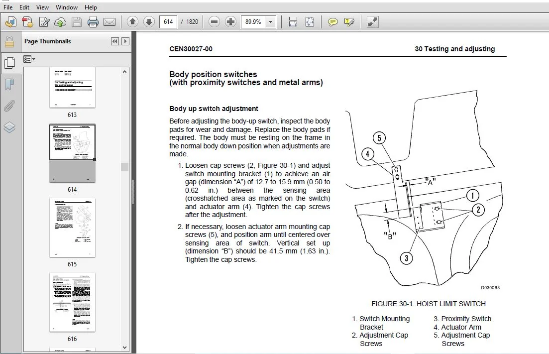
30. Testing and adjusting
This section explains measuring instruments and measuring methods for testing and adjusting, and method of adjusting each part. The standard values and judgement criteria for testing and adjusting are explained in Testing and adjusting.
40. Troubleshooting
This section explains how to find out failed parts and how to repair them. The troubleshooting is divided by failure modes.
50. Disassembly and assembly
This section explains the special tools and procedures for removing, installing, disassembling, and assembling each component, as well as precautions for them. In addition, tightening torque and weight of components are also explained.
90. Diagrams and drawings
This section gives hydraulic circuit diagrams and electrical circuit diagrams.
TABLE OF CONTENTS:
KOMATSU 860E-1KT DUMP TRUCK SERVICE REPAIR MANUAL (SN:A30004-A30030)
COVER
................................................................................................................................   1
00 Index and foreword
................................................................................................................   3
	Index.............................................................................................................................   3
		Composition of shop manual....................................................................................................   4
		Table of contents.............................................................................................................   6
	Foreword, safety and general information..........................................................................................  35
		Foreword......................................................................................................................  38
		How to read the shop manual...................................................................................................  39
			Composition of shop manual................................................................................................  39
			Revision and distribution.................................................................................................  39
			Symbols...................................................................................................................  40
		General safety................................................................................................................  41
			Safety rules..............................................................................................................  41
			Safety features...........................................................................................................  41
			Fire extinguisher and first aid kit.......................................................................................  41
			Clothing and personal items...............................................................................................  41
			Leaving the operator seat.................................................................................................  42
			Mounting and dismounting..................................................................................................  42
			Fire prevention for fuel and oil..........................................................................................  42
			Precautions with high temperature fluids..................................................................................  43
			Asbestos dust hazard prevention...........................................................................................  43
			Prevention of injury by work equipment....................................................................................  43
			Unauthorized modification.................................................................................................  43
			Precautions when using ROPS...............................................................................................  43
			Precautions for attachments...............................................................................................  44
			Precautions for starting the truck........................................................................................  44
		Precautions before operating the truck........................................................................................  44
			Safety at the worksite....................................................................................................  44
			Fire prevention...........................................................................................................  45
			Ventilation in enclosed areas.............................................................................................  45
			Preparing for operation...................................................................................................  45
			Mirrors, windows and lights...............................................................................................  45
			In operator cab (before starting the engine)..............................................................................  45
			Seat Belts................................................................................................................  45
		Precautions while operating the truck.........................................................................................  46
			When starting the engine..................................................................................................  46
			General truck operation...................................................................................................  46
			Ensuring good visibility..................................................................................................  46
			Traveling.................................................................................................................  47
			Traveling in reverse......................................................................................................  47
			Traveling on slopes.......................................................................................................  47
			Operating on snow or ice..................................................................................................  47
			Avoid damage to dump body.................................................................................................  47
			Driving near high voltage cables..........................................................................................  48
			When dumping..............................................................................................................  48
			Working on loose ground...................................................................................................  48
			When loading..............................................................................................................  48
			Parking the truck.........................................................................................................  48
			Towing....................................................................................................................  48
		Working near batteries........................................................................................................  49
			Battery hazard prevention.................................................................................................  49
			Starting with booster cables..............................................................................................  50
			Jump starting with receptacles............................................................................................  50
		Precautions before performing service.........................................................................................  51
			Warning tag...............................................................................................................  51
			Stopping the engine.......................................................................................................  51
			Proper tools..............................................................................................................  51
			Securing the dump body....................................................................................................  51
		While performing maintenance..................................................................................................  52
			Keep the truck clean......................................................................................................  52
			Attachments...............................................................................................................  52
			Working under the truck...................................................................................................  52
			Rotating fan and belts....................................................................................................  52
			Adding fuel or oil........................................................................................................  52
			Use of lighting...........................................................................................................  52
			Radiator coolant level....................................................................................................  53
			Precautions with the battery..............................................................................................  53
			Precautions with high pressure oil........................................................................................  53
			Handling high pressure hoses..............................................................................................  53
			Precautions when performing maintenance near high temperature or high pressure............................................  53
			Waste materials...........................................................................................................  53
		Tires.........................................................................................................................  54
			Handling tires............................................................................................................  54
			Storing tires after removal...............................................................................................  54
		Precautions for performing repairs............................................................................................  55
			Engine shutdown procedure after AC drive system failure...................................................................  55
		Precautions for welding on the truck..........................................................................................  56
		Handling electrical equipment and hydraulic components........................................................................  57
			Points to remember when handling electrical equipment.....................................................................  57
			Points to remember when handling hydraulic equipment......................................................................  63
		How to read electric wire code................................................................................................  65
		Standard torque tables........................................................................................................  68
			Effect of special lubricants on fasteners and standard torque values......................................................  68
			Standard tightening torques for SAE hex head cap screw and nut assemblies.................................................  69
			Standard assembly torques for 12-point, grade 9 cap screws (SAE)..........................................................  70
			Standard assembly torques for class 10.9 capscrews and class 10 nuts......................................................  70
			Standard tightening torques for fittings..................................................................................  71
		Conversion tables.............................................................................................................  73
			Common conversion multipliers.............................................................................................  73
	Operating instructions............................................................................................................  77
		Preparing for operation.......................................................................................................  79
			Walk around inspection....................................................................................................  79
		Engine start-up...............................................................................................................  84
		After engine start-up.........................................................................................................  85
		Precautions during truck operation............................................................................................  86
		Operating on a haul road......................................................................................................  87
		Starting on a grade with a loaded truck.......................................................................................  87
		Passing.......................................................................................................................  88
		Loading.......................................................................................................................  88
		Dumping.......................................................................................................................  88
			Raising The Dump Body.....................................................................................................  88
			Lowering The Dump Body (When dumping on flat ground):.....................................................................  89
			Lowering The Dump Body (When dumping over a berm or into a crusher):......................................................  90
		Trolley operating instructions................................................................................................  91
			Operating in trolley line mode............................................................................................  91
			Getting on line...........................................................................................................  91
			Operating on trolley......................................................................................................  92
			Getting off line..........................................................................................................  92
			Line status signals.......................................................................................................  93
			Trolley disconnect........................................................................................................  93
			Traffic consideration for trolley line operation..........................................................................  94
			Approaching slow moving vehicles in a trolley assisted truck..............................................................  94
			Operating slow moving vehicles on trolley assist ramps....................................................................  95
			Truck failure while on trolley............................................................................................  95
		Using the speed control feature...............................................................................................  96
		Safe parking procedures.......................................................................................................  96
		Normal engine shutdown procedure..............................................................................................  97
		Sudden loss of engine power...................................................................................................  98
		Fuel depletion................................................................................................................  98
		Towing........................................................................................................................  99
			Special Wiring Harness....................................................................................................  99
			Towing Procedure..........................................................................................................  99
		Disabled truck operation...................................................................................................... 102
			Steering and brake system................................................................................................. 102
			Components Required....................................................................................................... 102
			Hookup.................................................................................................................... 103
			Disabled truck dumping procedure.......................................................................................... 104
			Hookup.................................................................................................................... 104
			Raising the Body.......................................................................................................... 104
			Lowering the Body......................................................................................................... 105
01 Specification
..................................................................................................................... 107
	Specification and technical data.................................................................................................. 107
		Specification drawing......................................................................................................... 109
		Specifications................................................................................................................ 110
		Weight table.................................................................................................................. 112
		Fuel, coolant and lubricants.................................................................................................. 113
			Mixing rate of water and anti-freeze...................................................................................... 113
			Suspension cylinder oil and nitrogen specifications....................................................................... 114
10 Structure, functions and maintenance standard
..................................................................................... 117
	Cab air conditioning.............................................................................................................. 117
		General information........................................................................................................... 118
			Environmental impact of air conditioning.................................................................................. 118
			Air conditioning for off-highway vehicles................................................................................. 118
		Principles of refrigeration................................................................................................... 119
			Air conditioning.......................................................................................................... 119
			Refrigeration - the act of cooling........................................................................................ 119
			The refrigeration cycle................................................................................................... 119
		Air conditioning system components............................................................................................ 121
			Relays.................................................................................................................... 121
			Fan motor and speed control............................................................................................... 121
			Cab air filter............................................................................................................ 121
			Heater core............................................................................................................... 121
			Actuators................................................................................................................. 121
			Compressor (refrigerant pump)............................................................................................. 123
			Service valves............................................................................................................ 123
			Condenser................................................................................................................. 123
			Receiver-drier............................................................................................................ 123
			Expansion valve........................................................................................................... 124
			Accumulator............................................................................................................... 124
			Evaporator core........................................................................................................... 124
		Air conditioning system electrical circuit.................................................................................... 125
			Thermostat................................................................................................................ 125
			Compressor clutch......................................................................................................... 125
			Trinary™ switch........................................................................................................... 126
	Steering circuit.................................................................................................................. 129
		Steering circuit operation.................................................................................................... 131
		Steering circuit components................................................................................................... 133
			Steering control unit..................................................................................................... 133
			High pressure filter...................................................................................................... 133
			Steering accumulators..................................................................................................... 133
			Bleed down manifold....................................................................................................... 134
			Steering accumulator bleed down solenoid.................................................................................. 136
			Hoist up limit solenoid................................................................................................... 136
			Quick disconnect ports.................................................................................................... 137
			Flow amplifier............................................................................................................ 137
		Flow amplifier operation...................................................................................................... 138
			No steer.................................................................................................................. 138
			Steering left............................................................................................................. 140
			Steering right............................................................................................................ 142
			No steer, external shock load............................................................................................. 144
		Steering/brake pump operation................................................................................................. 147
			Normal operation.......................................................................................................... 147
			Neutral position.......................................................................................................... 148
			Full pump volume.......................................................................................................... 149
			Half pump volume.......................................................................................................... 149
		Steering cylinder wear data................................................................................................... 150
	Hoist circuit..................................................................................................................... 153
		Hoist circuit operation....................................................................................................... 155
		Hoist circuit components...................................................................................................... 156
			Hydraulic tank............................................................................................................ 156
			Hoist pump................................................................................................................ 156
			High pressure filters..................................................................................................... 156
			Hoist valve............................................................................................................... 156
			Inlet sections............................................................................................................ 157
			Tank ports (front) spool section.......................................................................................... 157
			Work ports (rear) spool section........................................................................................... 157
			Hoist pilot valve......................................................................................................... 158
			Bleed down manifold....................................................................................................... 158
			Hoist limit solenoid...................................................................................................... 158
			Pilot operated check valve................................................................................................ 158
			Overcenter manifold....................................................................................................... 159
		Hoist pilot valve operation................................................................................................... 160
			Float position with body down............................................................................................. 160
			Power up operation........................................................................................................ 162
			Hold operation............................................................................................................ 164
			Power down operation...................................................................................................... 166
			Float operation........................................................................................................... 168
		Hoist cylinder wear data...................................................................................................... 170
	Brake circuits.................................................................................................................... 173
		General information........................................................................................................... 175
		Service brake circuit operation............................................................................................... 176
		Secondary braking system and auto apply....................................................................................... 176
		Rear wheel brake lock circuit operation....................................................................................... 178
		Parking brake circuit operation............................................................................................... 180
			Normal operation (key switch ON, engine on)............................................................................... 180
		Brake warning circuit operation............................................................................................... 183
		Brake assembly wear data...................................................................................................... 185
	Suspensions....................................................................................................................... 187
		General information........................................................................................................... 188
		Front suspension wear data.................................................................................................... 188
		Rear suspension wear data..................................................................................................... 189
	Electrical system, 24 volt........................................................................................................ 191
		Battery supply system......................................................................................................... 193
		Auxiliary control cabinet components.......................................................................................... 194
			24VDC to 12VDC converter.................................................................................................. 194
			Diode board - DB1......................................................................................................... 194
			Power distribution terminals.............................................................................................. 194
			Control power relay....................................................................................................... 195
			Fuse blocks............................................................................................................... 196
		Relay boards.................................................................................................................. 196
			Relay boards RB1, RB3, RB4, RB5........................................................................................... 196
			Relay boards RB6, RB7, RB8, RB9........................................................................................... 198
			Relay functions........................................................................................................... 198
		Body position switches (With proximity switch and metal arm).................................................................. 200
			Body-up switch............................................................................................................ 200
			Hoist limit switch........................................................................................................ 201
		Body position switches (With proximity switch and magnet)..................................................................... 202
			Proximity switch operation................................................................................................ 202
			Body-up Switch............................................................................................................ 202
			Hoist limit switch........................................................................................................ 202
	Interface module (IM)............................................................................................................. 205
		General information........................................................................................................... 206
		Sensors....................................................................................................................... 206
			Temperature sensors....................................................................................................... 206
			Pressure sensors.......................................................................................................... 206
		Interface module inputs and outputs........................................................................................... 207
	Drive system...................................................................................................................... 213
		SR rectifier module........................................................................................................... 215
		ST module (auxiliary voltage inverter)........................................................................................ 215
			Technical Data............................................................................................................ 218
		SD phase modules.............................................................................................................. 219
		SR/ST/SD module removal....................................................................................................... 219
		Inverter cabinet layout....................................................................................................... 220
		Inverter cabinet water flow................................................................................................... 220
		Field regulator............................................................................................................... 221
			Technical Data............................................................................................................ 221
		Field regulator (discharge resistor).......................................................................................... 221
			Technical Data............................................................................................................ 221
		Gate unit power supply........................................................................................................ 222
			Technical Data............................................................................................................ 222
		Gate unit power supply (diode)................................................................................................ 222
			Technical Data............................................................................................................ 222
		Gate unit power supply (tuning resistor)...................................................................................... 222
			Technical Data............................................................................................................ 222
		Control power filter.......................................................................................................... 222
			Technical Data............................................................................................................ 222
		Filter for TCU................................................................................................................ 223
			Technical Data............................................................................................................ 223
		Terminal block bus bar........................................................................................................ 223
			Technical Data............................................................................................................ 223
		Fuses (analog sensor voltage)................................................................................................. 224
			Technical Data............................................................................................................ 224
		Fuses (field regulator)....................................................................................................... 224
			Technical Data............................................................................................................ 224
		Fuses (fuse holder for field regulator)....................................................................................... 224
			Technical Data............................................................................................................ 224
		Fuses (control power and trolley box contactor)............................................................................... 225
			Technical Data............................................................................................................ 225
		Diode modules................................................................................................................. 225
			Technical Data............................................................................................................ 225
		Support capacitors............................................................................................................ 226
			Technical Data............................................................................................................ 226
		3-Phase capacitor bank (for ST module output voltage)......................................................................... 226
			Technical Data............................................................................................................ 226
		Air-cooled inductors (for ST module).......................................................................................... 227
			Technical Data............................................................................................................ 227
		3-Phase transformer (for ST module)........................................................................................... 227
			Technical Data............................................................................................................ 227
		Diagnostics box............................................................................................................... 228
		Diagnostic and system monitoring panel........................................................................................ 229
			Device name: DB101........................................................................................................ 229
			Technical Data............................................................................................................ 229
		Current transducers........................................................................................................... 230
			Device names:............................................................................................................. 230
			U101ŠU104 (Current to motor A)............................................................................................ 230
			U105ŠU106 (Current to chopper A-C)........................................................................................ 230
			U201ŠU204 (Current to motor B)............................................................................................ 230
			U205ŠU206 (Current to chopper B-D)........................................................................................ 230
			Technical Data............................................................................................................ 230
			Technical Data............................................................................................................ 230
		Current transducers (for ST module output).................................................................................... 231
			Technical Data............................................................................................................ 231
		Voltage transducers........................................................................................................... 231
			Technical Data............................................................................................................ 231
		Voltage transducers (for ST module output).................................................................................... 232
			Technical Data............................................................................................................ 232
		Voltage transducers (SiBAS® 24V DC bus monitoring)............................................................................ 232
		Analog inclinometer........................................................................................................... 233
			Technical Data............................................................................................................ 233
		DC link capacitors............................................................................................................ 233
			Technical Data............................................................................................................ 233
		Ground tie capacitor.......................................................................................................... 234
			Technical Data............................................................................................................ 234
		Low-inductance bus bar assembly............................................................................................... 234
		Free-wheeling diode for low-inductance bus bars............................................................................... 235
		Contactor (grid box and main blower motor).................................................................................... 235
			Technical Data............................................................................................................ 235
		Contactor (control power)..................................................................................................... 236
			Technical Data............................................................................................................ 236
		Contactor (DC contactors)..................................................................................................... 236
			Technical Data............................................................................................................ 236
		Contactor (crowbar bypass).................................................................................................... 237
			Technical Data............................................................................................................ 237
		Temperature probes (PT100 style).............................................................................................. 237
			Technical Data............................................................................................................ 237
		Coolant inlet temperature sensor.............................................................................................. 237
			Technical Data............................................................................................................ 238
		Coolant outlet temperature sensor (external pad style)........................................................................ 238
			IGBT module heat sink temperature sensor.................................................................................. 238
				Device names: PT101ŠPT103 [Sensors for inverters A101ŠA103]........................................................... 238
				PT201ŠPT203 [Sensors for inverters A201ŠA203]......................................................................... 238
				PT104 and PT204 [Sensors for choppers 1 and 2 respectively]........................................................... 238
				PT105 and PT205 [Sensors for ST module (A301) and SR module (A1) respectively]........................................ 238
		Coolant outlet temperature sensor (internal style)............................................................................ 238
			Technical Data............................................................................................................ 238
		Coolant outlet temperature sensor (external pad style)........................................................................ 239
			Technical Data............................................................................................................ 239
		Circuit breakers.............................................................................................................. 239
			Technical Data............................................................................................................ 239
		Inner circulating blower fan.................................................................................................. 240
		Coolant pump.................................................................................................................. 240
			Technical Data............................................................................................................ 240
		Motor for coolant pump........................................................................................................ 241
			Technical Data............................................................................................................ 241
		Coolant pressure sensor....................................................................................................... 241
		Inner radiator................................................................................................................ 241
		Ground voltage monitoring resistors........................................................................................... 242
		Protection thyristor assembly (crowbar)....................................................................................... 242
		Discharge reactor............................................................................................................. 243
		Main blower motor............................................................................................................. 243
			Technical Data............................................................................................................ 243
		Grid box...................................................................................................................... 244
			Technical Data............................................................................................................ 244
		Grid box blower motor......................................................................................................... 244
			Technical Data............................................................................................................ 244
		Grid box blower motor grease fittings......................................................................................... 245
		Main alternator............................................................................................................... 245
			Stator.................................................................................................................... 245
			Rotor..................................................................................................................... 246
			Bearings.................................................................................................................. 246
			Electrical connection..................................................................................................... 246
			Cooling and ventilation................................................................................................... 246
			Rotating rectifier section................................................................................................ 246
			Technical Data............................................................................................................ 247
			Main alternator circuit diagram........................................................................................... 248
			IGBT Š inverter/chopper phase module...................................................................................... 249
				Device names: A101ŠA103 (Inverter A section).......................................................................... 249
				A201ŠA203 (Inverter B section)........................................................................................ 249
				A104 (Chopper A section).............................................................................................. 249
				A204 (Chopper B section).............................................................................................. 249
			Troubleshooting information............................................................................................... 251
			Main input rectifier module............................................................................................... 252
				Device name: A1....................................................................................................... 252
				Internal circuit diagram.............................................................................................. 253
		Upper ground tie resistor..................................................................................................... 254
			Device Name: R11.1-R11.2.................................................................................................. 254
			Technical Data............................................................................................................ 254
		Lower ground tie resistor..................................................................................................... 254
			Device name: R11.3-R11.4.................................................................................................. 254
			Technical Data............................................................................................................ 254
			Troubleshooting........................................................................................................... 255
			Fault diagnosis........................................................................................................... 255
		Speed sensor, alternator...................................................................................................... 256
			Technical Data............................................................................................................ 256
		Speed sensors, wheel motors................................................................................................... 257
			Technical Data............................................................................................................ 257
		Traction motor................................................................................................................ 258
			Device name: Motor 1 (grid box side of the truck), Motor 2 (operator cab side of the truck)............................... 258
			Technical Data............................................................................................................ 258
		Grid box...................................................................................................................... 259
			Device name: M04.......................................................................................................... 259
			Technical Data............................................................................................................ 259
	SIBAS® IGBT rack components....................................................................................................... 261
		SiBAS®32 Traction Control Unit (TCU).......................................................................................... 263
			Overview of the SiBAS®32 systems.......................................................................................... 264
				Features.............................................................................................................. 264
				General technical specifications, operating conditions................................................................ 264
				Permissible temperature range......................................................................................... 264
				Permissible limit value for air humidity.............................................................................. 265
				Permissible power supply voltage range................................................................................ 265
				Permissible mechanical loads.......................................................................................... 265
				Protection measures against electrical hazards........................................................................ 265
				Application........................................................................................................... 265
			Removing and installing the SiBAS®32 cards................................................................................ 268
				Removal with 24V OFF! (ESD protection required)....................................................................... 268
				Installation with 24V OFF! (ESD protection required).................................................................. 268
			SiBAS®32 card device names................................................................................................ 269
			Structure of SiBAS®32 card part number.................................................................................... 270
				Development status, downward compatibility............................................................................ 270
			SiBAS®32 card interchangeability.......................................................................................... 271
				Use of service interfaces............................................................................................. 272
				Connection of the service unit........................................................................................ 272
				Maintenance........................................................................................................... 272
				Cleaning.............................................................................................................. 273
			SiBAS®32 card interactions................................................................................................ 274
			SiBAS®32 card detailed information........................................................................................ 277
				Blower subassembly.................................................................................................... 277
					Device name: N/A.................................................................................................. 277
					Application....................................................................................................... 277
					Battery replacement............................................................................................... 279
					Rules for handling lithium batteries.............................................................................. 279
					Replacement of the battery in the fan subassembly................................................................. 279
				CPU card.............................................................................................................. 280
					Device name: G011................................................................................................. 280
					Application....................................................................................................... 281
					Front panel....................................................................................................... 281
					Technical data.................................................................................................... 282
				DSP card.............................................................................................................. 283
					Device name: G019, G027 and G35................................................................................... 283
					Application....................................................................................................... 283
					Front panel....................................................................................................... 283
					Technical data.................................................................................................... 284
				I/O card.............................................................................................................. 285
					Device name: G043................................................................................................. 285
					Application....................................................................................................... 285
					Front panel....................................................................................................... 286
					Technical data.................................................................................................... 287
				TRACO card (optional)................................................................................................. 288
					Device name: G003................................................................................................. 288
					Application....................................................................................................... 288
					Front panel....................................................................................................... 289
					Technical data.................................................................................................... 290
				Input voltage/frequency card.......................................................................................... 291
					Device name: L055, L063 and L071.................................................................................. 291
					Application....................................................................................................... 291
					Technical data.................................................................................................... 292
				I/O analog card....................................................................................................... 293
					Device name: L079 and L087........................................................................................ 293
					Technical data.................................................................................................... 295
				I/O analog card....................................................................................................... 296
					Device name: L095 and L103........................................................................................ 296
					Application....................................................................................................... 296
					Technical data.................................................................................................... 298
				Output pulse amplifier card........................................................................................... 299
					Device name: L115, L123, L131, L139 and L147...................................................................... 299
					Application....................................................................................................... 299
					Technical data.................................................................................................... 301
				Input temperature sensor card......................................................................................... 302
					Device name: L155 and L163........................................................................................ 302
					Application....................................................................................................... 302
					Technical data.................................................................................................... 304
				UWS card.............................................................................................................. 305
					Device name: G055, G063, G071 and G079............................................................................ 305
					Application....................................................................................................... 305
					Technical data.................................................................................................... 307
				Digital input card.................................................................................................... 308
					Device name: G103, G111, G119, G127 and G135...................................................................... 308
					Application....................................................................................................... 308
					Technical data.................................................................................................... 310
				Power start-up unit card.............................................................................................. 311
					Device name: G163................................................................................................. 311
					Application....................................................................................................... 311
					Technical data.................................................................................................... 313
				Binary output contactor drive card.................................................................................... 314
					Device name: C019, C027 and C035.................................................................................. 314
					Application....................................................................................................... 314
					Technical data.................................................................................................... 316
				24V / 24V power supply................................................................................................ 317
					Device name: C045, C105, C129..................................................................................... 317
					Application....................................................................................................... 317
					Testing the power supply card..................................................................................... 318
					Technical data.................................................................................................... 319
				24V / 15V power supply................................................................................................ 320
					Device name: C069, C087........................................................................................... 320
					Application....................................................................................................... 320
					Testing the power supply card..................................................................................... 321
					Technical data.................................................................................................... 322
				24V / 5V power supply................................................................................................. 323
					Device name: C153................................................................................................. 323
					Application....................................................................................................... 323
					Testing the power supply card..................................................................................... 324
					Technical data.................................................................................................... 325
	Reserve engine oil system......................................................................................................... 327
		General information........................................................................................................... 329
		Operation..................................................................................................................... 330
			LED monitor light......................................................................................................... 330
		Remote tank fill system....................................................................................................... 331
	Wheel motor transmission.......................................................................................................... 333
		General information........................................................................................................... 334
		Transmission wear data........................................................................................................ 337
20
Standard value table ............................................................................................................. 341
	Standard value table.............................................................................................................. 341
		Standard value table for truck................................................................................................ 342
30 Testing and adjusting
............................................................................................................. 347
	General information............................................................................................................... 347
		Special tool list............................................................................................................. 348
	Cab air conditioning.............................................................................................................. 351
		General information........................................................................................................... 352
		Service tools and equipment................................................................................................... 353
			Recovery/recycle station.................................................................................................. 353
			Leak detector............................................................................................................. 353
			Manifold gauge set........................................................................................................ 354
			Service valves............................................................................................................ 355
			Vacuum pump............................................................................................................... 355
		Detecting leaks............................................................................................................... 356
		System performance test....................................................................................................... 357
		Checking system oil........................................................................................................... 358
		System flushing............................................................................................................... 359
		Installing the manifold gauge set............................................................................................. 360
			Purging air from the service hoses........................................................................................ 360
		Recovering and recycling refrigerant.......................................................................................... 361
			Draining oil from previous recovery cycle................................................................................. 362
			Recovery cycle............................................................................................................ 362
			Recycling procedure....................................................................................................... 362
		Evacuating the air conditioning system........................................................................................ 363
		Charging the air conditioning system.......................................................................................... 364
		A/C drive belt checkout procedure............................................................................................. 365
			Pulley alignment.......................................................................................................... 365
			Belt tension check........................................................................................................ 365
	Steering, brake cooling and hoist hydraulic system................................................................................ 369
		General information on system checkout........................................................................................ 371
		Steering system checkout procedures........................................................................................... 371
			Steering pump pressure control adjustments................................................................................ 372
			Steering control valve and flow amplifier leakage test.................................................................... 373
			Bleed down manifold leakage test.......................................................................................... 374
			Shock and suction valve pressure tests.................................................................................... 375
		Steering system checkout data sheet........................................................................................... 377
		Toe-in adjustment............................................................................................................. 378
		Brake cooling and hoist system checkout procedures............................................................................ 379
			Pressure gauge locations.................................................................................................. 379
			Brake cooling circuit test................................................................................................ 380
			Power up relief pressure test............................................................................................. 380
			Power down relief pressure test........................................................................................... 381
			Counterbalance valve pressure check....................................................................................... 382
			Counterbalance valve adjustment........................................................................................... 383
		Brake cooling and hoist system checkout data sheet............................................................................ 384
		Hydraulic system flushing..................................................................................................... 385
			Hydraulic System Flushing Procedure....................................................................................... 385
			Front suspension pressure test............................................................................................ 392
			Rear suspension pressure test............................................................................................. 392
			Steering cylinder leakage test............................................................................................ 393
			Hoist cylinder leakage test............................................................................................... 393
	Brake system...................................................................................................................... 395
		General information on system checkout........................................................................................ 396
		Brake circuit checkout procedure.............................................................................................. 396
			Initial system setup...................................................................................................... 397
			Brake lock / secondary braking checkout................................................................................... 398
			Parking brake checkout.................................................................................................... 400
			Service brake checkout.................................................................................................... 403
			Blended braking checkout.................................................................................................. 403
			Low brake accumulator pressure and auto apply checkout.................................................................... 404
			Parking brake control logic checkout...................................................................................... 406
			Auto apply solenoid hydraulic circuit troubleshooting..................................................................... 407
			Brake lock control logic checkout......................................................................................... 408
		Brake system checkout data sheet.............................................................................................. 411
		Brake piston leakage test..................................................................................................... 416
		Wet disc brake bleeding procedure............................................................................................. 416
		Parking brake bleeding procedure.............................................................................................. 417
		Parking brake leakage test.................................................................................................... 417
		Brake valve bench test and adjustment......................................................................................... 418
			Test setup procedure...................................................................................................... 419
			Brake valve output pressure adjustment.................................................................................... 419
			Final test and adjustment................................................................................................. 420
		Dual relay valve bench test and adjustment.................................................................................... 421
			Test setup procedure...................................................................................................... 422
			Relay valve output pressure adjustment.................................................................................... 422
	Accumulators and suspensions...................................................................................................... 425
		Accumulator charging and storage.............................................................................................. 427
			Accumulator charging procedures........................................................................................... 427
			Precharge maintenance..................................................................................................... 430
			Accumulator storage procedure............................................................................................. 431
			Bladder storage........................................................................................................... 431
			Installing a bladder accumulator from storage............................................................................. 431
		Accumulator leak testing...................................................................................................... 432
		Suspension oiling and charging procedures..................................................................................... 434
			Equipment list............................................................................................................ 434
			Installing the charging kit............................................................................................... 434
			Removing the charging kit................................................................................................. 435
			Support blocks for oiling and charging dimensions......................................................................... 435
			Front suspension oiling................................................................................................... 436
			Front suspension nitrogen charging........................................................................................ 437
			Rear suspension oiling.................................................................................................... 439
			Rear suspension nitrogen charging......................................................................................... 441
		Suspension pressure test...................................................................................................... 442
	Payload meter..................................................................................................................... 445
		Payload meter initial setting procedure....................................................................................... 447
			Starting communications................................................................................................... 447
			Configure payload meter................................................................................................... 447
			Setting truck number...................................................................................................... 449
			Clean truck tare.......................................................................................................... 450
			Inclinometer calibration.................................................................................................. 450
	KOMTRAX Plus...................................................................................................................... 453
		KOMTRAX Plus and payload meter software....................................................................................... 455
			VHMS Tool Box Installation................................................................................................ 455
			VHMS Setting Tool Installation............................................................................................ 455
			Installing the PDM software............................................................................................... 455
		KOMTRAX Plus controller initial setting procedure............................................................................. 456
			KOMTRAX Plus controller setup procedure................................................................................... 456
			KOMTRAX Plus snapshot procedure........................................................................................... 459
			KOMTRAX Plus download procedure........................................................................................... 460
			KOMTRAX Plus FTP upload procedure......................................................................................... 461
			KOMTRAX Plus initialization forms......................................................................................... 462
		KOMTRAX Plus initialization check list........................................................................................ 463
		KOMTRAX Plus initialization form.............................................................................................. 465
		Precautions for replacing KOMTRAX Plus controller............................................................................. 466
		KOMTRAX Plus controller checkout procedure.................................................................................... 471
			Necessary equipment....................................................................................................... 471
			Preliminary............................................................................................................... 471
			Checkout procedure........................................................................................................ 472
	Interface module (IM)............................................................................................................. 475
		Interface module software..................................................................................................... 476
			Flashburn program installation............................................................................................ 476
			Interface module application code installation............................................................................ 477
			Interface module realtime data monitor software installation.............................................................. 477
		Interface module checkout procedures.......................................................................................... 478
			Necessary equipment....................................................................................................... 478
			Preliminary............................................................................................................... 479
			Check digital inputs to the interface module.............................................................................. 480
			Check analog inputs to the interface module............................................................................... 483
			Check serial interfaces to the interface module........................................................................... 484
			Check outputs from the interface module................................................................................... 484
	IGBT haul truck SIBAS® user manual, part 1........................................................................................ 487
		Abbreviations................................................................................................................. 489
		Precautions................................................................................................................... 491
		Qualified person.............................................................................................................. 491
		Customer monitor for SIBAS® 32 control units.................................................................................. 491
			Product description....................................................................................................... 491
			Version management........................................................................................................ 492
			Overview.................................................................................................................. 493
			Requirements.............................................................................................................. 493
		Installing and calling the customer monitor................................................................................... 494
			Installation.............................................................................................................. 494
				Environment variables................................................................................................. 494
			Communication with the SIBAS® 32 control unit............................................................................. 495
			Calling up the customer monitor........................................................................................... 496
				Start-up prompt....................................................................................................... 496
				Monitor prompt........................................................................................................ 497
			Notes on operation of the customer monitor................................................................................ 498
			Structure of a monitor command............................................................................................ 498
				Step 1: Selecting the menu title...................................................................................... 498
				Step 2: Selecting a menu entry in the menu box........................................................................ 498
				Step 3: Selecting a dialog box, if available.......................................................................... 499
				Step 4: Entering file or connector/signal names....................................................................... 499
			Command buffer............................................................................................................ 500
			Structure of the monitor windows.......................................................................................... 500
		Window menu................................................................................................................... 501
			Commands for Opening, Altering and Closing Windows........................................................................ 501
			"Window Work open"........................................................................................................ 501
			"Window Lines open"....................................................................................................... 501
			"Window Tile"............................................................................................................. 501
			"Window Bars open"........................................................................................................ 501
				Options............................................................................................................... 501
			"Window Set".............................................................................................................. 501
				Options............................................................................................................... 501
			"Window Cascade".......................................................................................................... 501
			"Window Close"............................................................................................................ 501
			"Window close All"........................................................................................................ 501
			"Window Exit"............................................................................................................. 501
		Set Menu...................................................................................................................... 502
			"Set Port"................................................................................................................ 502
				Options............................................................................................................... 502
			"Set Baudrate"............................................................................................................ 502
				Options............................................................................................................... 502
			"Set String".............................................................................................................. 503
				Example............................................................................................................... 504
			"Set Make"................................................................................................................ 504
				Options............................................................................................................... 504
				Example 1: INIT.MON start-up control of the Customer Monitor.......................................................... 505
				Example 2: Any monitor batch file with freely selectable file name (incl. path)....................................... 505
			"Set Execute"............................................................................................................. 506
				Options............................................................................................................... 506
				Example............................................................................................................... 506
			"Set Record".............................................................................................................. 506
				Options............................................................................................................... 506
			"Set DIN-Bus"............................................................................................................. 507
			"Set TCN"................................................................................................................. 507
			"Set Timeout"............................................................................................................. 507
				Options............................................................................................................... 507
			"Set Wait"................................................................................................................ 507
				Options............................................................................................................... 507
			"Set Color"............................................................................................................... 507
				Options............................................................................................................... 507
			"Set Info"................................................................................................................ 508
			"Set comment"............................................................................................................. 508
			"Set CHAR Set"............................................................................................................ 508
			"Set Quit"................................................................................................................ 508
		Applic. Menu.................................................................................................................. 509
			"Applic. Func.Package".................................................................................................... 509
			"Applic. Connector"....................................................................................................... 510
				Options............................................................................................................... 510
				Example............................................................................................................... 511
			"Applic. View"............................................................................................................ 511
				Options............................................................................................................... 511
				Example............................................................................................................... 511
			"Applic. Signal".......................................................................................................... 511
			"Applic. Observer"........................................................................................................ 512
				Options............................................................................................................... 512
				Possible time slices:................................................................................................. 512
				Options............................................................................................................... 513
				Two options........................................................................................................... 513
				Notes on the display of connectors.................................................................................... 515
			"Applic. Buffer".......................................................................................................... 516
				Options............................................................................................................... 516
			"Applic. Report".......................................................................................................... 516
			"Applic. Legitimation".................................................................................................... 516
				Options............................................................................................................... 516
			"Applic. Menu"............................................................................................................ 517
			"Applic. Traco"........................................................................................................... 517
				Options............................................................................................................... 517
			"Applic. Environment"..................................................................................................... 517
		Hardw. Menu................................................................................................................... 519
			Hardware-Oriented Access via the Customer Monitor......................................................................... 519
			"Hardw. Flash"............................................................................................................ 519
				Options............................................................................................................... 519
				Requirements.......................................................................................................... 519
				Example............................................................................................................... 520
				Deleting and loading.................................................................................................. 520
				The EPROM for the communication drivers............................................................................... 520
			"Hardw. Clock"............................................................................................................ 520
				Options............................................................................................................... 520
			"Hardw. DSP".............................................................................................................. 521
			"Hardw. BCD".............................................................................................................. 521
				Options............................................................................................................... 521
				Example............................................................................................................... 521
			"Hardw. RESET"............................................................................................................ 521
				Options............................................................................................................... 521
			"Hardw. Info"............................................................................................................. 522
				Hardware/Operating system............................................................................................. 522
				Application and tools................................................................................................. 522
				Communication module.................................................................................................. 522
				Displaying the loading date........................................................................................... 522
			"Hardw. User Flash"....................................................................................................... 523
				Options............................................................................................................... 523
			"Hardw. Sys. Flash"....................................................................................................... 523
				Options............................................................................................................... 523
			"Hardw. BOOT DSP"......................................................................................................... 524
				Requirements.......................................................................................................... 524
				DSP5600x Signal Processing Unit and TRACO............................................................................. 524
				Inverter processing unit.............................................................................................. 526
				Access to the Signal Processing Unit.................................................................................. 526
			"Hardw. Flash"............................................................................................................ 526
				Options............................................................................................................... 526
				Requirements.......................................................................................................... 526
				Example............................................................................................................... 526
				Deleting and loading.................................................................................................. 527
				The EPROM for the communication drivers............................................................................... 527
				User Data Flash (UDF)................................................................................................. 527
			"Hardw. RESET"............................................................................................................ 527
				Options............................................................................................................... 527
			"Hardw. ZR"............................................................................................................... 528
			"Hardw. BOOT ZR".......................................................................................................... 528
				The following procedure is necessary:................................................................................. 528
		Graphic Menu.................................................................................................................. 529
			Commands for Displaying Line Graphics..................................................................................... 529
			"Graphic Load"............................................................................................................ 529
				Options............................................................................................................... 529
			"Graphic Position"........................................................................................................ 529
				Options............................................................................................................... 529
			"Graphic Time/Div"........................................................................................................ 530
				Options............................................................................................................... 530
			"Graphic Unit/Div"........................................................................................................ 530
				Options............................................................................................................... 530
			"Graphic Display"......................................................................................................... 530
				Options............................................................................................................... 530
			"Graphic Color"........................................................................................................... 531
				Options............................................................................................................... 531
			"Graphic Format".......................................................................................................... 531
				Options............................................................................................................... 531
	IGBT haul truck SIBAS® user manual, part 2........................................................................................ 533
		Traco Menu.................................................................................................................... 535
			HW-Traco.................................................................................................................. 535
				Options............................................................................................................... 536
			SW-Traco.................................................................................................................. 537
				Options............................................................................................................... 538
				ZR traco basic parameters:............................................................................................ 538
				ZR traco record signal table:......................................................................................... 538
			DAC_Traco................................................................................................................. 541
				Options............................................................................................................... 542
		Events Menu................................................................................................................... 543
			STatistics................................................................................................................ 544
			History................................................................................................................... 545
			LEL:Last EvL.............................................................................................................. 546
			LES:Last EvS.............................................................................................................. 548
			DLL:DC,LastL.............................................................................................................. 549
			DLS:DC,LastS.............................................................................................................. 550
			DAL:DC,All L.............................................................................................................. 551
			DAS:DC,All S.............................................................................................................. 552
			ML:Memory L............................................................................................................... 553
			MS:Memory S............................................................................................................... 554
			CN:Clear Norm............................................................................................................. 555
			CA:Clear All.............................................................................................................. 555
			Test-Code................................................................................................................. 555
			DS:Diag-Strc.............................................................................................................. 556
		User Menu..................................................................................................................... 557
			DAC_IO.................................................................................................................... 558
				Options............................................................................................................... 558
				Options............................................................................................................... 559
				Operat.Data........................................................................................................... 560
			Acc test.................................................................................................................. 567
			Engine_Test............................................................................................................... 567
			X_Test_Inx................................................................................................................ 570
			STate intern.............................................................................................................. 571
				Header:............................................................................................................... 571
				Vehicle Number:....................................................................................................... 571
				Powering system:...................................................................................................... 571
				TCU Operation Mode:................................................................................................... 571
				Component status listings:............................................................................................ 572
				Field regulator status:............................................................................................... 572
				Status gate unit power supply A:...................................................................................... 572
				Status gate unit power supply B:...................................................................................... 572
				ST inverter status.................................................................................................... 573
				Vehicle status........................................................................................................ 573
				Drive status:......................................................................................................... 573
				Operation status:..................................................................................................... 574
			Pedal calib............................................................................................................... 575
			Language.................................................................................................................. 576
			OFFline-test.............................................................................................................. 576
				Options............................................................................................................... 576
			Variables................................................................................................................. 577
				Examples:............................................................................................................. 577
			IV:Vehic-ID............................................................................................................... 579
			Commands.................................................................................................................. 579
				Discharge Dc link / Fire crowbar...................................................................................... 580
				Limp mode commands.................................................................................................... 580
			Settings.................................................................................................................. 581
			Parameters................................................................................................................ 582
			Temp_prot................................................................................................................. 584
		Appendix...................................................................................................................... 586
			Background commands....................................................................................................... 586
			Monitor commands for the central processing unit.......................................................................... 587
			Monitor commands for the signal processing unit........................................................................... 587
	Installing ZR / DSP software...................................................................................................... 589
		Monitor Program – Loading software into the SIBAS®............................................................................ 590
		Loading software into the DSP procedure....................................................................................... 590
		Loading a DSP program Inverter A.............................................................................................. 595
		Loading ZR software Prog. jumpers Reset....................................................................................... 609
	24V electrical system............................................................................................................. 613
		Body position switches (with proximity switches and metal arms)............................................................... 614
			Body up switch adjustment................................................................................................. 614
			Hoist limit switch adjustment............................................................................................. 615
			Service................................................................................................................... 615
		Body position switches (with proximity switches and magnets).................................................................. 616
			Body up switch adjustment................................................................................................. 616
			Hoist limit switch adjustment............................................................................................. 616
			Service................................................................................................................... 616
40 Troubleshooting
................................................................................................................... 621
	Cab air conditioning.............................................................................................................. 621
		Preliminary checks............................................................................................................ 623
		Diagnosis of gauge readings and system performance............................................................................ 623
		Troubleshooting by manifold gauge set readings................................................................................ 624
	Fuse and circuit breaker locations................................................................................................ 631
		Fuse and circuit breaker locations............................................................................................ 632
	Troubleshooting by fault code, part 1............................................................................................. 637
		Fault Code A001: Left front suspension pressure sensor signal high............................................................ 639
			Related circuit diagram................................................................................................... 639
		Fault Code A002: Left front suspension pressure sensor signal low............................................................. 640
			Related circuit diagram................................................................................................... 640
		Fault Code A003: Right front suspension pressure sensor signal high........................................................... 641
			Related circuit diagram................................................................................................... 641
		Fault Code A004: Right front suspension pressure sensor signal low............................................................ 642
			Related circuit diagram................................................................................................... 642
		Fault Code A005: Left rear suspension pressure sensor signal high............................................................. 643
			Related circuit diagram................................................................................................... 643
		Fault Code A006: Left rear suspension pressure sensor signal low.............................................................. 644
			Related circuit diagram................................................................................................... 644
		Fault Code A007: Right rear suspension pressure sensor signal high............................................................ 645
			Related circuit diagram................................................................................................... 645
		Fault Code A008: Right rear suspension pressure sensor signal low............................................................. 646
			Related circuit diagram................................................................................................... 646
		Fault Code A009: Incline sensor signal high................................................................................... 647
			Related circuit diagram................................................................................................... 647
		Fault Code A010: Incline sensor signal low.................................................................................... 648
			Related circuit diagram................................................................................................... 648
		Fault Code A011: Payload meter speed sensor signal has failed................................................................. 649
			Related circuit diagram................................................................................................... 649
		Fault Code A013: Body up switch has failed.................................................................................... 650
			Related circuit diagram................................................................................................... 650
		Fault Code A014: Payload meter checksum computation has failed................................................................ 651
			Related circuit diagram................................................................................................... 651
		Fault Code A016: Payload meter write to flash memory has failed............................................................... 652
			Related circuit diagram................................................................................................... 652
		Fault Code A017: Payload meter flash memory read has failed................................................................... 653
			Related circuit diagram................................................................................................... 653
		Fault Code A018: Right rear flat suspension cylinder warning.................................................................. 654
			Related circuit diagram................................................................................................... 655
		Fault Code A019: Left rear flat suspension cylinder warning................................................................... 656
			Related circuit diagram................................................................................................... 657
		Fault Code A022: Carryback load excessive..................................................................................... 658
			Related circuit diagram................................................................................................... 659
		Fault Code A100: An open circuit breaker has been detected on a relay board................................................... 661
			Related circuit diagram................................................................................................... 661
		Fault Code A101: High pressure detected across an hydraulic pump filter....................................................... 662
			Related circuit diagram................................................................................................... 663
		Fault Code A105: Fuel level sensor shorted to ground, indicating a false high fuel level...................................... 664
			Related circuit diagram................................................................................................... 665
		Fault Code A111: Low steering pressure warning for storage by VHMS............................................................ 666
			Related circuit diagram................................................................................................... 666
		Fault Code A115: Low steering precharge pressure detected..................................................................... 668
			Related circuit diagram................................................................................................... 669
		Fault Code A117: Low brake accumulator pressure warning for storage by VHMS................................................... 670
			Related circuit diagram................................................................................................... 670
		Fault Code A118: Brake pressure is low while in brake lock.................................................................... 672
			Related circuit diagram................................................................................................... 673
		Fault Code A126: Oil level in the hydraulic tank is low....................................................................... 674
			Related circuit diagram................................................................................................... 674
		Fault Code A127: IM-furnished +5 volt output for sensors is low............................................................... 676
			Related circuit diagram................................................................................................... 677
		Fault Code A128: IM-furnished +5 volt output for sensors is high.............................................................. 678
			Related circuit diagram................................................................................................... 679
		Fault Code A139: Low fuel warning for storage by VHMS and for use by A310..................................................... 680
			Related circuit diagram................................................................................................... 681
	Troubleshooting by fault code, part 2............................................................................................. 683
		Fault Code A145: Hydraulic temperature sensors cause advance of engine rpm to advance level 1 for cooling of hydraulic oil.... 686
			Related circuit diagram................................................................................................... 687
		Fault Code A146: Hydraulic temperature sensors cause advance of engine rpm to advance level 2 for cooling of hydraulic oil.... 688
			Related circuit diagram................................................................................................... 689
		Fault Code A152: Starter failure.............................................................................................. 690
			Related circuit diagram................................................................................................... 691
		Fault Code A153: Battery voltage is low with the truck in operation........................................................... 692
			Related circuit diagram................................................................................................... 693
		Fault Code A154: Battery charging voltage is excessive........................................................................ 694
			Related circuit diagram................................................................................................... 694
		Fault Code A155: Battery charging voltage is low.............................................................................. 695
			Related circuit diagram................................................................................................... 695
		Fault Code A158: Fuel level sensor is open or shorted high, indicating a false low fuel level................................. 696
			Related circuit diagram................................................................................................... 697
		Fault Code A159: (A30003 only) The battery 12 Volt circuit sensing is producing low readings.................................. 698
			Related circuit diagram................................................................................................... 698
		Fault Code A164: (A30003 only) The battery 12 Volt circuit sensing is producing high readings................................. 699
			Related Circuit Diagram................................................................................................... 699
		Fault Code A166: Left rear hydraulic oil temperature sensor is low............................................................ 700
			Related circuit diagram................................................................................................... 701
		Fault Code A167: Right rear hydraulic oil temperature sensor is low........................................................... 702
			Related circuit diagram................................................................................................... 703
		Fault Code A168: Left front hydraulic oil temperature sensor is low........................................................... 704
			Related circuit diagram................................................................................................... 705
		Fault Code A169: Right front hydraulic oil temperature sensor is low.......................................................... 706
			Related circuit diagram................................................................................................... 707
		Fault Code A170: Left rear hydraulic oil temperature sensor is high........................................................... 708
			Related circuit diagram................................................................................................... 708
		Fault Code A171: Right rear hydraulic oil temperature sensor is high.......................................................... 709
			Related circuit diagram................................................................................................... 709
		Fault Code A172: Left front hydraulic oil temperature sensor is high.......................................................... 710
			Related circuit diagram................................................................................................... 710
		Fault Code A173: Right front hydraulic oil temperature sensor is high......................................................... 711
			Related circuit diagram................................................................................................... 711
		Fault Code A182: (A30003 only) The battery 12 Volt battery tap has high voltage............................................... 712
			Related circuit diagram................................................................................................... 713
		Fault Code A183: (A30003 only) The battery 12 Volt battery tap has low voltage................................................ 714
			Related circuit diagram................................................................................................... 715
		Fault Code A184: J1939 data link is not connected............................................................................. 716
			Related circuit diagram................................................................................................... 717
		Fault Code A190: (A30003 only) The automatic lubrication system has announced a fault......................................... 718
		Fault Code A190: (A30004 & Up) Auto lube control has detected an incomplete lube cycle........................................ 720
			Related circuit diagram................................................................................................... 721
		Fault Code A194: Left front hydraulic oil temperature is high................................................................. 722
			Related circuit diagram................................................................................................... 722
		Fault Code A195: Right front hydraulic oil temperature is high................................................................ 723
			Related circuit diagram................................................................................................... 723
		Fault Code A196: Left rear hydraulic oil temperature is high.................................................................. 724
			Related circuit diagram................................................................................................... 724
		Fault Code A197: Right rear hydraulic oil temperature is high................................................................. 725
			Related circuit diagram................................................................................................... 725
		Fault Code A198: Hoist pressure 1 sensor is high.............................................................................. 726
			Related circuit diagram................................................................................................... 726
		Fault Code A199: Hoist pressure 2 sensor is high.............................................................................. 727
			Related circuit diagram................................................................................................... 727
		Fault Code A200: Steering pressure sensor is high............................................................................. 728
			Related circuit diagram................................................................................................... 728
		Fault Code A201: Brake pressure sensor is high................................................................................ 729
			Related circuit diagram................................................................................................... 729
		Fault Code A202: Hoist pressure 1 sensor is low............................................................................... 730
			Related circuit diagram................................................................................................... 730
		Fault Code A203: Hoist pressure 2 sensor is low............................................................................... 731
			Related circuit diagram................................................................................................... 731
		Fault Code A204: Steering pressure sensor is low.............................................................................. 732
			Related circuit diagram................................................................................................... 732
		Fault Code A205: Brake pressure sensor is low................................................................................. 733
			Related circuit diagram................................................................................................... 733
		Fault Code A206: Ambient temperature sensor is high........................................................................... 734
			Related circuit diagram................................................................................................... 734
		Fault Code A207: Ambient temperature sensor is low............................................................................ 735
			Related circuit diagram................................................................................................... 735
	Troubleshooting by fault code, Part 3............................................................................................. 737
		Fault Code A213: Parking brake should have applied but is detected as not having applied...................................... 739
			Related circuit diagram................................................................................................... 742
		Fault Code A214: Parking brake should have released but is detected as not having released.................................... 744
			Related circuit diagram................................................................................................... 746
		Fault Code A215: Brake auto apply valve circuit is defective.................................................................. 748
			Related circuit diagram................................................................................................... 749
		Fault Code A216: An open or short to ground has been detected in the parking brake command valve circuit...................... 750
			Related circuit diagram................................................................................................... 751
		Fault Code A223: Excessive engine cranking has occurred or a jump start has been attempted.................................... 752
			Related circuit diagram................................................................................................... 753
		Fault Code A230: Parking brake has been requested while truck still moving.................................................... 754
			Related circuit diagram................................................................................................... 755
		Fault Code A231: The body is up while traveling or with selector in forward or neutral........................................ 756
		Fault Code A233: Drive System Control Link is not connected................................................................... 758
			Related circuit diagram................................................................................................... 759
		Fault Code A235: Steering accumulator is in the process of being bled down.................................................... 760
			Related circuit diagram................................................................................................... 761
		Fault Code A236: The steering accumulator has not properly bled down after 90 seconds......................................... 762
			Related circuit diagram................................................................................................... 763
		Fault Code A237: The CAN/RPC connection to the display is open................................................................ 764
			Related circuit diagram................................................................................................... 765
		Fault Code A238: Drive System and IM are reporting different park brake status................................................ 766
			Related circuit diagram................................................................................................... 767
		Fault Code A239: The Drive System and IM are reporting different brake lock status............................................ 768
			Related circuit diagram................................................................................................... 769
		Fault Code A240: The keyswitch input to the Interface Module is open.......................................................... 770
			Related circuit diagram................................................................................................... 770
		Fault Code A242: Fuel gauge within the dash display panel is defective........................................................ 771
			Related circuit diagram................................................................................................... 771
		Fault Code A243: Engine coolant temperature gauge within the dash display panel is defective.................................. 772
			Related circuit diagram................................................................................................... 772
		Fault Code A244: Drive system temperature gauge within the dash display panel is defective.................................... 773
			Related circuit diagram................................................................................................... 773
		Fault Code A245: Hydraulic oil temperature gauge within the dash display panel is defective................................... 774
			Related circuit diagram................................................................................................... 774
		Fault Code A246: Payload meter reports truck overload......................................................................... 775
			Related circuit diagram................................................................................................... 775
		Fault Code A247: Low steering pressure warning for display to operator........................................................ 776
			Related circuit diagram................................................................................................... 776
		Fault Code A248: Status module within the dash display panel is defective..................................................... 777
			Related circuit diagram................................................................................................... 777
		Fault Code A249: Red warning lamp within the dash display (driven by IM) is shorted........................................... 778
			Related circuit diagram................................................................................................... 778
		Fault Code A250: Battery voltage is low with the truck parked................................................................. 779
			Related circuit diagram................................................................................................... 780
		Fault Code A251: Sonalert used with the dash display (driven by IM) is open or shorted to ground.............................. 781
			Related circuit diagram................................................................................................... 782
		Fault Code A252: Start enable output circuit is either open or shorted to ground.............................................. 783
			Related circuit diagram................................................................................................... 783
		Fault Code A253: Steering bleed circuit is not open while running............................................................. 784
			Related circuit diagram................................................................................................... 785
		Fault Code A254: (A30003 Only) The 5 minute idle circuit is either open or shorted to ground.................................. 786
			Related circuit diagram................................................................................................... 786
		Fault Code A256: Red warning lamp in the dash display (driven by IM) is open.................................................. 787
			Related circuit diagram................................................................................................... 787
		Fault Code A257: Payload CAN/RPC is not connected............................................................................. 788
			Related circuit diagram................................................................................................... 789
		Fault Code A258: Steering accumulator bleed pressure switch circuit is defective.............................................. 790
			Related circuit diagram................................................................................................... 790
	Troubleshooting by fault code, Part 4............................................................................................. 793
		Fault Code A260: Park brake failure........................................................................................... 796
			Related circuit diagram................................................................................................... 797
		Fault Code A261: Low brake accumulator pressure warning for display to operator............................................... 798
			Related circuit diagram................................................................................................... 798
		Fault Code A262: Steering bleed valve circuit open during shutdown............................................................ 800
			Related circuit diagram................................................................................................... 801
		Fault Code A264: Park brake relay circuit is defective........................................................................ 802
			Related circuit diagram................................................................................................... 803
		Fault Code A265: Service brake failure........................................................................................ 804
			Related circuit diagram................................................................................................... 805
		Fault Code A266: Selector switch was not in park while attempting to crank engine............................................. 806
			Related circuit diagram................................................................................................... 806
		Fault Code A267: Park brake was not set while attempting to crank engine...................................................... 807
			Related circuit diagram................................................................................................... 807
		Fault Code A268: Secondary engine shutdown while cranking..................................................................... 808
			Related circuit diagram................................................................................................... 808
		Fault Code A270: Brake lock switch power supply is not on when required....................................................... 810
			Related circuit diagram................................................................................................... 811
		Fault Code A271: Shifter not in gear.......................................................................................... 812
			Related circuit diagram................................................................................................... 813
		Fault Code A272: Brake lock switch power supply is not off when required...................................................... 814
			Related circuit diagram................................................................................................... 815
		Fault Code A273: A fault has been detected in the hoist or steering pump filter pressure switch circuit....................... 816
			Related circuit diagram................................................................................................... 816
		Fault Code A274: A brake setting fault has been detected...................................................................... 818
			Related circuit diagram................................................................................................... 819
		Fault Code A275: A starter has been detected as engaged without a cranking attempt............................................ 820
			Related circuit diagram................................................................................................... 821
		Fault Code A277: Park brake applied while loading............................................................................. 822
			Related circuit diagram................................................................................................... 823
		Fault Code A278: Service brake applied while loading.......................................................................... 824
			Related circuit diagram................................................................................................... 825
		Fault Code A279: Low Steering Pressure Switch bad............................................................................. 826
			Related circuit diagram................................................................................................... 826
		Fault Code A280: Steering accumulator bled switch bad......................................................................... 827
			Related circuit diagram................................................................................................... 827
		Fault Code A281: Brake lock degrade switch bad................................................................................ 828
			Related circuit diagram................................................................................................... 829
		Fault Code A282: The number of excessive cranking counts and jump starts without the engine running has reached 7............. 830
			Related circuit diagram................................................................................................... 831
		Fault Code A283: (A30004 & Up) An engine shutdown delay was aborted because the parking brake was not set..................... 832
			Related circuit diagram................................................................................................... 833
		Fault Code A284: (A30004 & Up) An engine shutdown delay was aborted because the secondary shutdown switch was operated........ 834
			Related circuit diagram................................................................................................... 835
		Fault Code A285: (A30004 & Up) The park brake was not set when the keyswitch was turned off................................... 836
			Related circuit diagram................................................................................................... 837
		Fault Code A286: (A30004 & Up) A fault was detected in the shutdown delay relay circuit....................................... 838
			Related circuit diagram................................................................................................... 839
		Fault Code A292: (A30004 & Up) The shutdown delay relay has remained on after the latched keyswitch circuit is off............ 840
			Related circuit diagram................................................................................................... 841
		Fault Code A295: The right front park brake is not setting up................................................................. 842
			Related circuit diagram................................................................................................... 842
		Fault Code A296: The left front park brake is not setting up.................................................................. 843
			Related circuit diagram................................................................................................... 843
		Fault Code A297:The right rear park brake is not setting up................................................................... 844
			Related circuit diagram................................................................................................... 844
		Fault Code A298: The left rear park brake is not setting up................................................................... 845
			Related circuit diagram................................................................................................... 845
		Fault Code A299: The right front park brake is not releasing.................................................................. 846
			Related circuit diagram................................................................................................... 846
		Fault Code A300: The left front park brake is not releasing................................................................... 847
			Related circuit diagram................................................................................................... 847
		Fault Code A301: The right rear park brake is not releasing................................................................... 848
			Related circuit diagram................................................................................................... 848
		Fault Code A302: The left rear park brake is not releasing.................................................................... 849
			Related circuit diagram................................................................................................... 849
	Troubleshooting by fault code, part 5............................................................................................. 851
		Fault Code A303: Shifter is defective......................................................................................... 854
			Related circuit diagram................................................................................................... 855
		Fault Code A304: (A30004 & Up) Auto lube grease level fault................................................................... 856
			Related circuit diagram................................................................................................... 856
		Fault Code A305: (A30004 & Up) Auto lube circuit is defective................................................................. 858
			Related circuit diagram................................................................................................... 859
		Fault Code A309: No brakes applied when expected.............................................................................. 860
			Related circuit diagram................................................................................................... 861
		Fault Code A310: Low fuel warning............................................................................................. 862
			Related circuit diagram................................................................................................... 863
		Fault Code A311: Brake lock switch is on when it should not be................................................................ 864
			Related circuit diagram................................................................................................... 865
		Fault Code A312: (A30004 & Up) DCDC converter 12 volt circuit sensing is producing low readings............................... 866
			Related circuit diagram................................................................................................... 866
		Fault Code A313: (A30004 & Up) DCDC converter 12 volt circuit sensing is producing high readings.............................. 867
			Related circuit diagram................................................................................................... 867
		Fault Code A315: (A30004 & Up) DCDC converter 12 volt circuit is low.......................................................... 868
			Related circuit diagram................................................................................................... 869
		Fault Code A316: Starter engagement has been attempted with engine running.................................................... 870
			Related circuit diagram................................................................................................... 871
		Fault Code A317: Operation of brake auto apply valve without a detected response.............................................. 872
			Related circuit diagram................................................................................................... 873
		Fault Code A318: Unexpected power loss to Interface Module.................................................................... 874
			Related circuit diagram................................................................................................... 874
		Fault Code A328: Drive system not powered up.................................................................................. 875
			Related circuit diagram................................................................................................... 875
		Fault Code A350: Overload on output 1B........................................................................................ 876
			Related circuit diagram................................................................................................... 876
		Fault Code A351: Overload on output 1E........................................................................................ 878
			Related circuit diagram................................................................................................... 879
		Fault Code A352: (A30003) Overload on output 1H............................................................................... 880
			Related circuit diagram................................................................................................... 880
		Fault Code A352: (A30004 & Up) Overload on output 1H.......................................................................... 881
			Related circuit diagram................................................................................................... 881
		Fault Code A353: Overload on output 1J........................................................................................ 882
			Related circuit diagram................................................................................................... 882
		Fault Code A354: Overload on output 1K........................................................................................ 883
			Related circuit diagram................................................................................................... 883
		Fault Code A355: Overload on output 1L........................................................................................ 884
			Related circuit diagram................................................................................................... 884
		Fault Code A356: Overload on output 1M........................................................................................ 885
			Related circuit diagram................................................................................................... 885
		Fault Code A357: Overload on output 1N........................................................................................ 886
			Related circuit diagram................................................................................................... 886
		Fault Code A358: Overload on output 1P........................................................................................ 887
			Related circuit diagram................................................................................................... 887
		Fault Code A359: Overload on output 1R........................................................................................ 888
			Related circuit diagram................................................................................................... 889
		Fault Code A360: Overload on output 1S........................................................................................ 890
			Related circuit diagram................................................................................................... 890
		Fault Code A361: (A30003) Overload on output 1T............................................................................... 891
			Related circuit diagram................................................................................................... 891
			None...................................................................................................................... 891
		Fault Code A361: (A30004 & Up) Overload on output 1T.......................................................................... 892
			Related circuit diagram................................................................................................... 893
		Fault Code A362: Overload on output 1U........................................................................................ 894
			Related circuit diagram................................................................................................... 894
		Fault Code A363: Overload on output 1X........................................................................................ 895
			Related circuit diagram................................................................................................... 895
		Fault Code A364: Overload on output 1Y........................................................................................ 896
			Related circuit diagram................................................................................................... 896
		Fault Code A365: Overload on output 1Z........................................................................................ 897
			Related circuit diagram................................................................................................... 897
	Drive system fault code table, Part 1............................................................................................. 899
		Summary....................................................................................................................... 901
			How to use this document.................................................................................................. 901
			Event code and diagnosis message.......................................................................................... 901
			Description............................................................................................................... 901
			Threshold................................................................................................................. 901
			Detection by.............................................................................................................. 901
			Possible reasons.......................................................................................................... 901
			Action to reset........................................................................................................... 901
			Action to repair.......................................................................................................... 902
			Operator displayed code................................................................................................... 902
			Note...................................................................................................................... 902
			Protection reactions...................................................................................................... 902
		EVENT CLASSIFICATION.......................................................................................................... 902
			Level 1: Warning.......................................................................................................... 903
			Level 2: Minor purposes................................................................................................... 903
			Level 3: Severe........................................................................................................... 903
	Drive system fault code table, Part 2............................................................................................. 939
	Drive system fault code table, Part 3............................................................................................. 979
	Drive system fault code table, Part 4.............................................................................................1039
	Drive system fault code table, Part 5.............................................................................................1093
	Drive system fault code table, Part 6.............................................................................................1167
	Drive system fault code table, Part 7.............................................................................................1217
	Troubleshooting electric wheel motor..............................................................................................1291
		FAULT TABLE...................................................................................................................1292
	Reserve engine oil system.........................................................................................................1301
		Pumping unit LED signals......................................................................................................1303
			Circuit fuses.............................................................................................................1303
50 Disassembly and assembly
..........................................................................................................1305
	General information...............................................................................................................1305
		Special tool list.............................................................................................................1306
	Cab air conditioning..............................................................................................................1315
		Replacement of air conditioning system components.............................................................................1317
			Hoses and fittings........................................................................................................1317
			Lines.....................................................................................................................1317
			Expansion valve...........................................................................................................1317
			Receiver-drier............................................................................................................1317
			Thermostat................................................................................................................1317
			Compressor................................................................................................................1318
			Accumulator...............................................................................................................1318
			Clutch....................................................................................................................1318
		Diasassembly and assembly of compressor clutch................................................................................1319
			Removal of the clutch assembly............................................................................................1319
			Removal of the pulley.....................................................................................................1321
			Installation of the pulley................................................................................................1321
			Installation of the clutch assembly.......................................................................................1322
	Wheels, spindles and rear axle....................................................................................................1325
		General information for tires and rims........................................................................................1327
			Storage and handling......................................................................................................1327
		Wheel stud maintenance........................................................................................................1328
			Front wheel studs.........................................................................................................1328
			Rear wheel studs..........................................................................................................1328
		Removal and installation of front wheel.......................................................................................1330
			Removal...................................................................................................................1330
			Installation..............................................................................................................1330
		Removal and installation of rear wheels.......................................................................................1332
			Removal...................................................................................................................1332
			Installation..............................................................................................................1333
		Removal and installation of tires.............................................................................................1334
			Removal...................................................................................................................1334
			Installation..............................................................................................................1335
		Removal and installation of front wheel hub and spindle.......................................................................1337
			Removal...................................................................................................................1338
			Spindle Removal Procedure (off of the truck)..............................................................................1341
			Installation..............................................................................................................1343
		Disassembly and assembly of front wheel hub and spindle.......................................................................1344
			Disassembly...............................................................................................................1344
			Cleaning and inspection...................................................................................................1345
			Assembly..................................................................................................................1347
			Wheel bearing adjustment..................................................................................................1347
			Seal assembly gap check and adjustment....................................................................................1348
			Floating seal installation................................................................................................1349
			Speed sensor installation and adjustment..................................................................................1351
		Removal and installation of wheel motor.......................................................................................1352
			Preparation...............................................................................................................1352
			Removal...................................................................................................................1352
			Cleaning and inspection...................................................................................................1353
			Installation..............................................................................................................1354
		Removal and installation of rear axle.........................................................................................1357
			Removal...................................................................................................................1357
			Cleaning and inspection...................................................................................................1358
			Installation..............................................................................................................1359
		Removal and installation of anti-sway bar.....................................................................................1359
			Removal...................................................................................................................1359
			Installation..............................................................................................................1360
		Removal and installation of pivot pin.........................................................................................1361
			Removal...................................................................................................................1361
			Installation..............................................................................................................1361
		Pivot eye and bearing service.................................................................................................1362
			Bearing removal...........................................................................................................1362
			Bearing installation......................................................................................................1362
			Pivot eye repair..........................................................................................................1363
		Removal and installation of electric motor....................................................................................1364
			Removal...................................................................................................................1364
			Installation..............................................................................................................1364
		Disassembly and assembly of wheel motor transmission..........................................................................1365
			Disassembly...............................................................................................................1365
			Cleaning and inspection...................................................................................................1371
			Assembly..................................................................................................................1372
		Disassembly and assembly of low speed carrier.................................................................................1383
			Disassembly...............................................................................................................1383
			Inspection................................................................................................................1384
			Assembly..................................................................................................................1385
		Disassembly and assembly of high speed carrier................................................................................1388
			Disassembly...............................................................................................................1388
			Inspection................................................................................................................1389
			Assembly..................................................................................................................1390
	Brake system......................................................................................................................1395
		Removal and installation of brake valve.......................................................................................1397
			Removal...................................................................................................................1397
			Installation..............................................................................................................1398
		Disassembly and assembly of brake valve.......................................................................................1398
			Disassembly...............................................................................................................1398
			Cleaning and inspection...................................................................................................1402
			Assembly..................................................................................................................1402
		Removal and installation of dual relay valve..................................................................................1406
			Removal...................................................................................................................1406
			Installation..............................................................................................................1407
		Disassembly and assembly of dual relay valve..................................................................................1407
			Disassembly...............................................................................................................1407
			Cleaning and inspection...................................................................................................1408
			Assembly..................................................................................................................1408
		Removal and installation of brake manifold....................................................................................1409
			Removal...................................................................................................................1409
			Installation..............................................................................................................1410
		Disassembly and assembly of brake manifold....................................................................................1410
			Disassembly...............................................................................................................1410
			Assembly..................................................................................................................1410
		Removal and installation of brake accumulator.................................................................................1411
			Removal...................................................................................................................1411
			Installation..............................................................................................................1412
		Disassembly and assembly of brake accumulator.................................................................................1412
			Disassembly...............................................................................................................1412
			Cleaning and inspection...................................................................................................1414
			Assembly..................................................................................................................1414
		Disassembly and assembly of wheel brake.......................................................................................1416
			Disassembly...............................................................................................................1417
			Cleaning and inspection...................................................................................................1420
			Assembly..................................................................................................................1421
			Floating ring seal assembly and installation..............................................................................1427
		Removal and installation of rear brake assembly...............................................................................1431
			Removal...................................................................................................................1431
			Installation..............................................................................................................1431
	Steering system...................................................................................................................1437
		Removal and installation of steering control unit.............................................................................1439
			Removal...................................................................................................................1439
			Installation..............................................................................................................1440
		Disassembly and assembly of steering control unit.............................................................................1441
			Disassembly...............................................................................................................1441
			Assembly..................................................................................................................1443
		Removal and installation of steering column...................................................................................1446
			Removal...................................................................................................................1446
			Inspection................................................................................................................1446
			Installation..............................................................................................................1447
		Removal and installation of steering wheel....................................................................................1448
			Removal...................................................................................................................1448
			Installation..............................................................................................................1448
		Removal and installation of bleed down manifold...............................................................................1450
			Removal...................................................................................................................1450
			Installation..............................................................................................................1450
		Removal and installation of flow amplifier....................................................................................1452
			Removal...................................................................................................................1452
			Installation..............................................................................................................1452
		Disassembly and assembly of flow amplifier....................................................................................1452
			Disassembly...............................................................................................................1452
			Assembly..................................................................................................................1454
		Removal and installation of steering cylinders and tie rod....................................................................1455
			Removal...................................................................................................................1455
			Bearing replacement.......................................................................................................1455
			Installation..............................................................................................................1455
		Disassembly and assembly of steering cylinders................................................................................1457
			Disassembly...............................................................................................................1457
			Assembly..................................................................................................................1457
		Removal and installation of steering/brake pump...............................................................................1458
			Removal...................................................................................................................1458
			Installation..............................................................................................................1459
		Disassembly and assembly of steering/brake pump...............................................................................1461
			Disassembly...............................................................................................................1461
			Inspection................................................................................................................1464
			Assembly..................................................................................................................1467
			Driveshaft group..........................................................................................................1468
			Rotating group............................................................................................................1468
		Removal and installation of steering accumulators.............................................................................1471
			Removal Use vacuum pump kit (XB0887) to hold the oil back in the tank.....................................................1471
			Installation..............................................................................................................1472
		Disassembly and assembly of steering accumulators.............................................................................1472
			Disassembly...............................................................................................................1472
			Cleaning and Inspection...................................................................................................1474
			Assembly..................................................................................................................1474
	Suspensions.......................................................................................................................1479
		Removal and installation of front suspension..................................................................................1481
			Removal...................................................................................................................1481
			Installation..............................................................................................................1482
			Inspection................................................................................................................1487
		Minor front suspension repairs (lower bearing and seals)......................................................................1488
			Lower bearing retainer removal............................................................................................1488
			Lower bearing retainer installation.......................................................................................1488
		Major front suspension rebuild................................................................................................1489
			Disassembly...............................................................................................................1489
			Assembly..................................................................................................................1490
		Removal and installation of rear suspension...................................................................................1492
			Removal...................................................................................................................1493
			Installation..............................................................................................................1494
		Disassembly and assembly of rear suspension...................................................................................1495
			Disassembly...............................................................................................................1495
			Cleaning and Inspection...................................................................................................1496
			Assembly..................................................................................................................1496
	Hoist circuit.....................................................................................................................1499
		Removal and installation of hoist pump........................................................................................1501
			Removal...................................................................................................................1501
			Installation..............................................................................................................1502
		Disassembly and assembly of hoist pump........................................................................................1503
			Disassembly...............................................................................................................1503
			Inspection................................................................................................................1506
			Assembly..................................................................................................................1506
		Removal and installation of hoist valve.......................................................................................1511
			Removal...................................................................................................................1511
			Installation..............................................................................................................1512
		Disassembly and assembly of hoist valve.......................................................................................1512
			O-ring replacement........................................................................................................1512
			Disassembly of inlet section..............................................................................................1513
			Assembly of inlet section.................................................................................................1514
			Disassembly of rear spool section.........................................................................................1515
			Assembly of rear spool section............................................................................................1517
			Disassembly of front spool section........................................................................................1518
			Assembly of front spool section...........................................................................................1519
		Overcenter valve manifold service.............................................................................................1519
		Removal and installation of hoist pilot valve.................................................................................1520
			Removal...................................................................................................................1520
			Installation..............................................................................................................1520
		Disassembly and assembly of hoist pilot valve.................................................................................1521
			Disassembly...............................................................................................................1521
			Cleaning and inspection...................................................................................................1522
			Assembly..................................................................................................................1522
		Removal and installation of hoist cylinders...................................................................................1523
			Removal...................................................................................................................1523
			Installation..............................................................................................................1523
		Disassembly and assembly of hoist cylinders...................................................................................1525
			Disassembly...............................................................................................................1525
			Cleaning and inspection...................................................................................................1527
			Installation of the quill.................................................................................................1528
			Assembly..................................................................................................................1530
	Operator cab......................................................................................................................1533
		Removal and installation of operator cab......................................................................................1535
			Removal...................................................................................................................1536
			Installation..............................................................................................................1537
		Removal and installation of cab door..........................................................................................1539
			Removal...................................................................................................................1539
			Installation..............................................................................................................1539
		Disassembly and assembly of cab door..........................................................................................1539
			Removing door panel.......................................................................................................1539
			Installing door panel.....................................................................................................1540
			Replacing door window regulator...........................................................................................1540
			Replacing door handle or latch assembly...................................................................................1541
			Replacing door assembly seal and door hinge seal..........................................................................1542
			Replacing door opening seal...............................................................................................1542
			Removing door glass.......................................................................................................1543
			Installing door glass.....................................................................................................1544
		Adjustment of cab door........................................................................................................1546
			Door jamb bolt adjustment.................................................................................................1546
			Door handle plunger adjustment............................................................................................1547
		Removal and installation of side window glass.................................................................................1548
			Recommended tools and supplies............................................................................................1548
			Removal...................................................................................................................1549
			Installation..............................................................................................................1549
		Removal and installation of windshield and rear window glass..................................................................1550
			Removal...................................................................................................................1550
			Installation..............................................................................................................1550
		Removal and installation of windshield wiper motor............................................................................1551
			Removal...................................................................................................................1551
			Installation..............................................................................................................1551
		Removal and installation of windshield wiper arm..............................................................................1552
			Removal...................................................................................................................1552
			Installation..............................................................................................................1552
		Removal and installation of windshield wiper linkage..........................................................................1553
			Removal...................................................................................................................1553
			Installation..............................................................................................................1553
		Removal and installation of operator seat.....................................................................................1554
			Inspection................................................................................................................1554
			Removal...................................................................................................................1554
			Installation..............................................................................................................1554
		Removal and installation of passenger seat....................................................................................1555
			Removal...................................................................................................................1555
			Installation..............................................................................................................1555
		Removal and installation of seat belts (standard seats).......................................................................1556
			Removal...................................................................................................................1556
			Installation..............................................................................................................1556
		Removal and installation of seat belts (optional seats).......................................................................1558
			General...................................................................................................................1558
			Removal...................................................................................................................1558
			Installation..............................................................................................................1560
	Body and structures...............................................................................................................1565
		Removal and installation of dump body.........................................................................................1567
			Removal...................................................................................................................1567
			Inspection................................................................................................................1568
			Installation..............................................................................................................1569
		Removal and installation of body pads.........................................................................................1569
			Removal...................................................................................................................1569
			Installation..............................................................................................................1570
			Adjustment................................................................................................................1570
		Removal and installation of diagonal ladder/ hood and grille assembly.........................................................1572
			Removal...................................................................................................................1572
			Installation..............................................................................................................1572
		Removal and installation of right deck........................................................................................1573
			Removal...................................................................................................................1573
			Installation..............................................................................................................1574
		Removal and installation of left deck.........................................................................................1576
			Removal...................................................................................................................1576
			Installation..............................................................................................................1576
		Removal and installation of fuel tank.........................................................................................1578
			Removal...................................................................................................................1578
			Cleaning and inspection...................................................................................................1578
			Installation..............................................................................................................1580
		Removal and installation of fuel gauge sender.................................................................................1580
			Removal...................................................................................................................1580
			Installation..............................................................................................................1580
		Disassembly and assembly of fuel tank breather................................................................................1581
			Disassembly...............................................................................................................1581
			Assembly..................................................................................................................1581
		Removal and installation of hydraulic tank....................................................................................1582
			Removal...................................................................................................................1582
			Installation..............................................................................................................1582
	Three phase wheel motor...........................................................................................................1585
		Qualified personnel...........................................................................................................1586
		General.......................................................................................................................1586
			General safety information................................................................................................1586
		Handling......................................................................................................................1587
			Motor.....................................................................................................................1587
			Transport.................................................................................................................1588
			Storage...................................................................................................................1589
			Storage of new motors.....................................................................................................1589
			Storage of used motors....................................................................................................1590
		Maintenance...................................................................................................................1590
			General note:.............................................................................................................1590
		Motor.........................................................................................................................1590
			General...................................................................................................................1590
			Safety guidelines.........................................................................................................1591
		Maintenance intervals.........................................................................................................1592
		Maintenance work on the installed motor.......................................................................................1592
			Checking for external damage..............................................................................................1592
			Checking the connections..................................................................................................1593
			Regreasing the bearings...................................................................................................1593
			Applying grease to the bearings:..........................................................................................1593
			Checking the interior of the motor for water..............................................................................1594
		Disassembly...................................................................................................................1595
			Pressing off the coupling.................................................................................................1596
			Disassembly...............................................................................................................1597
				Rotor.................................................................................................................1597
			Removing the rubber seals and the air baffles.............................................................................1601
			Bearing and labyrinth ring................................................................................................1602
				Removal...............................................................................................................1602
		Maintenance work..............................................................................................................1603
			Stator Inspection.........................................................................................................1603
			Rotor Inspection..........................................................................................................1603
			Testing the insulation....................................................................................................1604
				High-voltage test.....................................................................................................1604
			Work on the bearings......................................................................................................1605
		Assembly......................................................................................................................1606
			Assembling the rubber seals and the air baffles...........................................................................1607
			Assembly after special repair work........................................................................................1609
				Bearing installation..................................................................................................1610
				Assemble the bearing..................................................................................................1614
				Cover installation....................................................................................................1615
			Assembling the bearing shield (N-end) at the stator frame.................................................................1616
			Bearing installation......................................................................................................1618
			Rotor installation........................................................................................................1620
			Labyrinth ring............................................................................................................1622
				Installation..........................................................................................................1622
			Installing accessories (D- and N-end).....................................................................................1624
			Running in the bearings...................................................................................................1628
			Coupling..................................................................................................................1629
				Installation..........................................................................................................1629
			Assembly conditions and instructions......................................................................................1630
			Tests.....................................................................................................................1630
		Repair work...................................................................................................................1631
			Replacing defective connecting leads......................................................................................1631
			Repairing the stator winding insulation...................................................................................1632
			Recommended consumables...................................................................................................1632
			Chemical cleaning agents..................................................................................................1632
				Chemical cleaning agents for outdoor use and for cleaning mechanical parts............................................1632
				Chemical cleaning agents for flange faces.............................................................................1632
			Chemical cleaning agents for windings.....................................................................................1633
				Chemical cleaning agents for windings.................................................................................1633
				Chemical cleaning agents for windings with severe damage and for oily windings........................................1633
			Rolling-contact bearing grease............................................................................................1633
			Assembly/disassembly agents for bearing seat..............................................................................1633
			Sealants for joining parts or gaps........................................................................................1633
			Locking agents for connecting elements....................................................................................1633
			Anti-corrosion agent......................................................................................................1633
			Assembly paste for temperature sensors....................................................................................1633
		List of tools.................................................................................................................1634
			Mounting devices for inserting and withdrawing the rotor horizontally.....................................................1634
			Press for expanding the coupling..........................................................................................1634
			Compression devices for pressing on or for support while pressing off.....................................................1635
			Pulling units with cross beam or disk.....................................................................................1637
			Aids......................................................................................................................1637
			Extraction devices........................................................................................................1638
		Repair parts list.............................................................................................................1638
			Paints for refinishing the painted parts or touching up damaged parts.....................................................1638
	Power module......................................................................................................................1641
		Removal and installation of power module......................................................................................1643
			General...................................................................................................................1643
			Preparation...............................................................................................................1643
			Removal...................................................................................................................1644
			Installation..............................................................................................................1649
		Removal and installation of alternator........................................................................................1651
			Removal...................................................................................................................1651
			Installation..............................................................................................................1653
		Removal and installation of engine............................................................................................1656
			Removal...................................................................................................................1656
			Service...................................................................................................................1657
			Installation..............................................................................................................1657
		Removal and installation of radiator..........................................................................................1657
			Removal...................................................................................................................1657
			Installation..............................................................................................................1659
		Repairing the radiator........................................................................................................1660
			Internal inspection.......................................................................................................1660
			External cleaning.........................................................................................................1660
			Disassembly...............................................................................................................1661
			Cleaning and inspection...................................................................................................1662
			Assembly..................................................................................................................1662
			Pressure testing..........................................................................................................1663
	Auto lubrication system...........................................................................................................1665
		Lubrication system priming....................................................................................................1666
		Disassembly and assembly of lubrication pump..................................................................................1666
			Disassembly...............................................................................................................1666
			Cleaning and Inspection...................................................................................................1668
			Assembly..................................................................................................................1668
	Main blower.......................................................................................................................1671
		Removing the main blower motor................................................................................................1672
		Disassembling the main blower motor...........................................................................................1678
		Assembling the main blower motor..............................................................................................1680
		Installing the main blower motor..............................................................................................1683
	Retarding grid....................................................................................................................1691
		Removing the grid blower motor................................................................................................1692
		Disassembling the grid blower motor...........................................................................................1694
		Assembling the grid blower motor..............................................................................................1696
		Installing the grid blower motor..............................................................................................1698
		Removing a grid element.......................................................................................................1701
	Control cabinet...................................................................................................................1705
		Draining and filling the IGBT coolant system..................................................................................1707
			Required tools/materials..................................................................................................1707
			Coolant mixture specification (distilled water : Antifrogen N)............................................................1707
			Draining and filling the coolant..........................................................................................1708
		Removing and installing the IGBT coolant pump assembly........................................................................1711
			Required tools/materials..................................................................................................1711
			Removal...................................................................................................................1712
90 Diagrams and drawings
.............................................................................................................1715
	Hydraulic circuit diagrams........................................................................................................1715
		EM1374 Hydraulic schematic
...................................................................................................1717
		EM6298 Brake schematic
.......................................................................................................1718
	Electrical circuit diagrams.......................................................................................................1719
		XS6701 Electric schematic
....................................................................................................1723
		HE488 Connector table and arrangment
.........................................................................................1761
	Electrical circuit diagrams - drive system........................................................................................1762
		HE486 Electric schematic
.....................................................................................................1766
		XS3381 Electric schematic
....................................................................................................1813
PLEASE NOTE:
⦁ This is the SAME MANUAL used by the dealerships to diagnose your vehicle
⦁ No waiting for couriers / posts as this is a PDF manual and you can download it within 2 minutes time once you make the payment.
⦁ Your payment is all safe and the delivery of the manual is INSTANT – You will be taken to the DOWNLOAD PAGE.
⦁ So have no hesitations whatsoever and write to us about any queries you may have : heydownloadss @gmail.com


Alec Ian –