

Komatsu 930E-4 Dump Truck Shop Manual PDF – CEBM017904 Complete Service & Repair Download (S/N A30462-A30600)
Original price was: $89.95.$59.95Current price is: $59.95.
Full 1027-page Komatsu 930E-4 Dump Truck Shop Manual (CEBM017904) covering serial numbers A30462-A30600. Complete AC electric drive, engine, Hydrair II suspension, wet disc brake, hydraulic and cab service procedures – instant PDF download.
Description
Komatsu 930E-4 Dump Truck Shop Manual – CEBM017904
The complete Komatsu 930E-4 Dump Truck Shop Manual, document number CEBM017904, covering truck serial numbers A30462 through A30600. This is the full 1027-page service, repair and overhaul reference for every major system on the 930E-4 off-highway rear dump truck – from the Komatsu SSDA16V160 diesel engine and GE AC electric propulsion, through the Hydrair II suspensions, wet disc brakes, hydraulic system, operator cab and lubrication schedules. Delivered as an instant-download PDF that runs on any laptop, tablet or desktop.
File Details
- Manual type: Shop Manual (service, repair, overhaul)
- Brand: Komatsu
- Model: 930E-4 Dump Truck
- Publication number: CEBM017904
- Serial numbers covered: A30462 – A30600
- Language: English
- Page count: 1027 pages
- File format: PDF
Chapters Covered
- Section A – General Information
- Section B – Structures
- Section C – Engine Systems
- Section D – Electric System (24VDC Non-Propulsion)
- Section E – Electric Propulsion and Control
- Section G – Drive Axle, Spindles and Wheels
- Section H – Hydrair II Suspensions
- Section J – Brake Circuit
- Section L – Hydraulic System
- Section M – Options and Special Tools
- Section N – Operator’s Cab
- Section P – Lubrication and Service
- Section Q – Alphabetical Index
- Section R – System Schematics
Section A – General Information
Opens with the full 930E-4 truck specification set: the Komatsu SSDA16V160 engine rated at 2700 HP (2014 kW) at 1900 rpm, GVW of 1,100,000 lbs (498,960 kg), GE GTA-41 alternator, GDY106 AC induction traction motors, 32.62:1 wheel motor gear ratio, and service capacities for crankcase (280 L / 74 gal), cooling system (594 L / 157 gal), fuel (4542 L / 1200 gal) and hydraulic tank (1325 L / 350 gal). Weight distribution tables, dump body dimensions, tire and rim sizing, standard torque charts and full metric/English conversion tables are all here.
Section B – Structures
Covers the deck structures (L.H., R.H. and center), grille, hood and diagonal ladder removal and installation, the dump body including body pads, body guides, hoist limit switch, body-up switch, body-up retention cable, rock ejectors and the complete fuel tank assembly with Wiggins quick-fill receivers, breather valve and gauge sender.
Section C – Engine Systems
The power module is handled as a roll-out unit, then radiator removal and rebuild – including L&M tube removal, seal installation, tube replacement and pressure testing at 103 kPa (15 psi) – cooling system filling procedure, power train alternator-to-engine alignment with the shim calculation method, and air cleaner servicing for both the main and safety filter elements.
Section D – Electric System (24VDC Non-Propulsion)
The 24 VDC system is fully documented: batteries, battery charging alternator, auxiliary control cabinet components, fuse block and circuit breaker charts, relay board RB1 through RB9 layouts, body-up and hoist limit switch adjustment, the Alarm Indicating Device (AID) system cards, and the entire Vehicle Health Monitoring System (VHMS) including initialization, download, FTP upload, troubleshooting and forms. The interface module checkout and coaxial cable fault-tree procedures are also included.
Section E – Electric Propulsion and Control
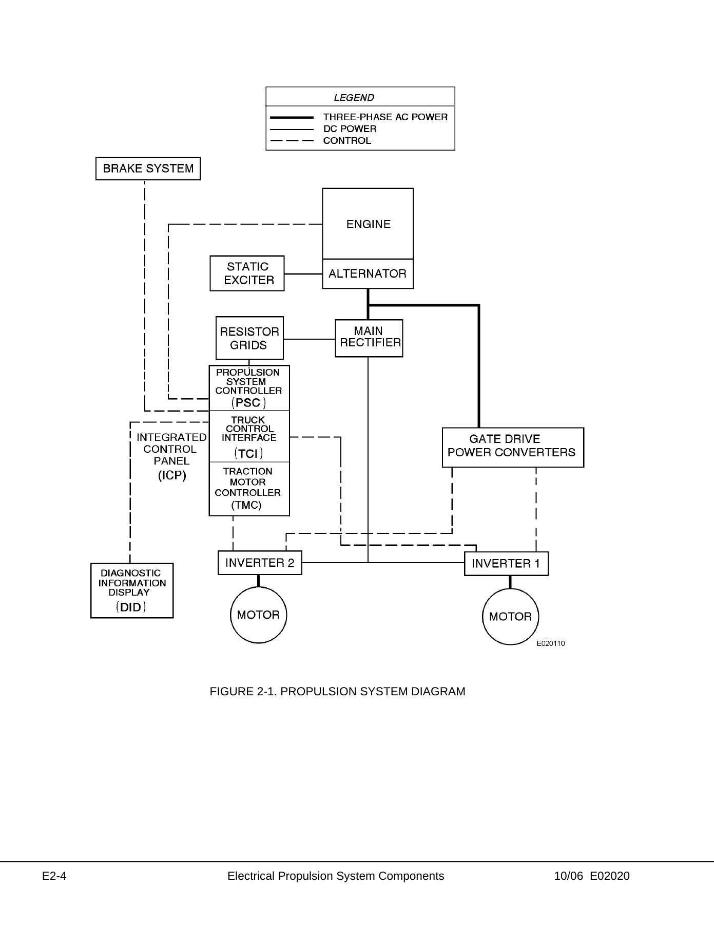
This is the AC drive heart of the truck. Section E2 explains the Propulsion System Controller (PSC), Truck Control Interface (TCI), Diagnostic Information Display (DID) panel and the full DID fault code tables for PSC, Inverter 1, Inverter 2 and TCI. Section E3 is the AC Drive System Electrical Checkout Procedure covering battery checks, PSC and TCI real-time data screens, calibrations, gate driver power converter testing, loadbox testing and phase module replacement.
Section G – Drive Axle, Spindles and Wheels
Tires and rims, wheel stud maintenance, front wheel hub and spindle removal and rebuild with the wheel bearing adjustment procedure, spherical bearing wear limits, steering cylinder and tie rod service, and the toe-in adjustment with the 3667 mm (144.37 in.) nominal tie-rod length for radial tires.
Section H – Hydrair II Suspensions
Front and rear Hydrair II suspension service – removal, installation, minor repairs to the lower bearing and seals, and full major rebuild. The oiling and charging procedure section gives the exact front and rear oiling heights, charging heights and nitrogen pressures required to restore proper ride height, load distribution and payload meter accuracy.
Section J – Brake Circuit
All-hydraulic actuated wet disc service brakes, parking brake, brake lock, secondary braking and automatic apply. Sections J3 through J7 cover the brake valve bench test and adjustment, dual relay valve rebuild, brake manifold, accumulator charging and precharge maintenance, wet disc brake assembly rebuild and floating ring seal installation, plus the brake circuit check-out procedure with the data sheet to record every measured pressure.
Section L – Hydraulic System
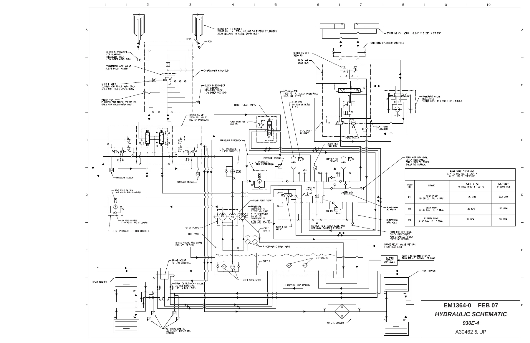
Hydraulic pump module and system overview, hoist pump rebuild including gear timing, hydraulic tank service and strainers, steering circuit operation with the flow amplifier cutaway diagrams, steering control unit rebuild, bleeddown manifold service, steering and brake pump removal and rebuild, steering accumulator charging, hoist circuit operation and component repair, hoist cylinders, overcenter valve manifold, hydraulic filters and the complete hydraulic check-out procedure with data sheet.
Section M – Options and Special Tools
Fire control systems – both the manual dry chemical system and the Checkfire electric detection and actuation system with linear detection wire – engine oil and coolant heaters, the special tools list with part numbers, the complete Payload Meter III (PLMIII) installation, calibration and troubleshooting, and the reserve engine oil system with remote fill.
Section N – Operator’s Cab
Truck cab removal and installation, cab doors and windows including adhesive-bonded glass replacement, windshield and rear glass installation, wiper motor and linkage, windshield washer, operator seat adjustment, heater and air conditioner service with the full R-134a refrigerant recovery, evacuation and charging procedure, and the complete operator cab controls layout with overhead status/warning indicator lamp chart.
Section P – Lubrication and Service
The lubrication chart and every service interval from 10 hour (daily) through 5000 hour checks – engine oil and filter changes, hydraulic filters and strainers, cooling system service, wheel motor oil sampling and filtering requirements, and the automatic lubrication system operation with injector adjustment and troubleshooting.
Section R – System Schematics
Complete set of hydraulic supply, brake cooling, steering and hoist schematics, hydraulic brake schematic, and the 35-sheet electrical schematic set covering main propulsion, 24V/15V power distribution, GE inverter firing, engine inputs and outputs, digital and analog I/O, overhead warning lights, work lights, retard lights, backup lights, clearance lights, fog lights, headlights, and the component locator sheets.
What This Komatsu 930E-4 Shop Manual Lets You Do
With 1027 pages of step-by-step procedures, torque values, oil and nitrogen capacities, service limits, adjustment numbers and diagrams, this 930E-4 shop manual supports everything from a routine 250-hour service to a full wet disc brake rebuild, a hydraulic pump reseal, a Hydrair II suspension rebuild, or a phase module replacement in the GE AC drive cabinet. The DID fault code tables alone give a technician a fast path into the electric propulsion system, and the brake circuit and hydraulic check-out data sheets let you record every pressure reading against factory values during a rebuild or a diagnostic call-out.
Getting the wrong torque figure, oil height, nitrogen precharge or wheel bearing preload on a truck of this size is expensive and unsafe. Having the actual CEBM017904 shop manual on hand means the spec you are tightening to, the pressure you are setting, and the clearance you are measuring against are the ones the truck was designed around – not a guess.
IMAGES PREVIEW
This Komatsu 930E-4 service manual is delivered as an instant PDF download after checkout. No shipping, no waiting on a CD or a paper binder. Open it on a laptop in the shop, pull it up on a tablet at the truck, or print the pages you need for the job. Every schematic, every exploded view, every table and every fault code is exactly where the original publication put it.


Reviews
There are no reviews yet.