Komatsu BULLDOZER D65EX -18 D65PX -18 D65WX-18 Shop Manual SEN06645-10 PDF
$36.95
Komatsu BULLDOZER D65EX -18 D65PX -18 D65WX-18 Shop Manual SEN06645-10 – PDF DOWNLOAD
Serial NUMBERS
D65EX- 90997
D65PX- 90997
D65WX-90997
and up
Description
Komatsu BULLDOZER D65EX -18 D65PX -18 D65WX-18 Shop Manual SEN06645-10 – PDF DOWNLOAD
FILE DETAILS:
Komatsu BULLDOZER D65EX -18 D65PX -18 D65WX-18 Shop Manual SEN06645-10 – PDF DOWNLOAD
Language : English
Pages :2926
Downloadable : Yes
File Type : PDF
DESCRIPTION:
Komatsu BULLDOZER D65EX -18 D65PX -18 D65WX-18 Shop Manual SEN06645-10 – PDF DOWNLOAD
Serial NUMBERS
D65EX- 90997
D65PX- 90997
D65WX-90997
and up
How to Read the Shop Manual
• Some of the attachments and options described in this shop manual may not be available in some areas. If
they are required, consult your Komatsu distributor.
• The materials and specifications are subject to change without notice.
• Shop Manuals are available for “machine part” and “engine part”. For the engine unit, see the shop manual
for the machine which has the same engine model.
• Actual machine may differ from the images which are contained in this manual. A typical model is shown in
the illustrations of this shop manual.
• The caution lamps, pilot lamps, and symbols of the switches on the machine monitor can be different in
accordance with the machine.
• For details of the symbols shown on the machine monitor, see Structure and Operation, “Caution
Lamps Shown on Machine Monitor” and “Pilot Lamps Shown on Machine Monitor”.
• For details of the switches of the machine monitor, see Testing and Adjusting, “Set and Operate Machine
Monitor”.
• For details of the switches, see the “Operation and Maintenance Manual”.
• All “AdBlue/DEF” shown on the machine monitor is referred to as “DEF” in the shop manual. Some machine
monitors installed to the product show “DEF” as “AdBlue/DEF” in the service mode. Thus, be sure to recognize
that “DEF” and “AdBlue/DEF” are the same when you read the shop manual.
REMARK
The illustrations in the shop manual reproduce the display of the machine monitor. They are not always the
same as the terminology in the shop manual.
Composition of the Shop Manual
This shop manual contains technical information necessary to perform services in workshops. It is divided into
the following chapters for the ease of use.
00 Index and Foreword
This section describes the index, foreword, safety, and basic information.
01 Specification
This section describes the specifications of the machine.
10 Structure and Function
This section describes the structure and operation of each component with respect to each system. “Structure
and Function” is helpful in not only understanding the structure of each component but performing troubleshooting.
20 Standard Value Table
This section describes the standard values for new machine and failure criteria for testing and adjusting, and
troubleshooting. Use the standard values table to check the standard values for testing and adjusting, and judge
troubles in troubleshooting.
30 Testing and Adjusting
This section describes the measuring tools and measuring methods for testing and adjusting as well as the adjusting
method of each part. The standard values and repair limit for TESTING AND ADJUSTING are described
in “Standard Value Table”.
40 Troubleshooting
This section describes troubleshooting of failure part and its remedy method on the occurrence of the failure.
Descriptions of troubleshooting are sorted by failure mode.
This section describes the special tools, work procedures, and safety precautions necessary for removal, installation,
disassembly, and assembly of the components and parts. In addition, tightening torques, quantity, and
weight of the coating materials, lubricants, and coolant necessary to these works are shown.
60 Maintenance Standard
This section describes the maintenance standard value of each component. The maintenance standard shows
the criteria and remedies for disassembly and assembly.
80 Others
This section describes the structure and function, testing and adjusting, and troubleshooting for all of the other
components or equipment which cannot be separately classified in the appendix.
90 Circuit Diagrams
This section describes hydraulic circuit diagrams and electrical circuit diagrams.
TABLE OF CONTENTS:
Komatsu BULLDOZER D65EX -18 D65PX -18 D65WX-18 Shop Manual SEN06645-10 – PDF DOWNLOAD
Cover 1
00 Index and Foreword 3
Index 4
Abbreviation List 21
Foreword, Safety, Basic Information 27
How to Read the Shop Manual 27
Safety Notice for Operation 29
Precautions to Prevent Fire 37
Procedures If Fire Occurs 39
Precautions When You Discard Waste Materials 40
Procedures for Exhaust Gas Regulations 41
Precautions for DEF 42
General Character and Precautions for Handling 42
Precautions When You Add 42
Precautions for Storage 42
Precautions for Fire Hazard and Leakage 42
Other Precautions 42
Store DEF 43
Precautions When You Handle Hydraulic Equipment 44
Precautions When You Disconnect and Connect Pipings 47
Precautions When You Handle Electrical Equipment 54
Precautions When You Handle Fuel System Equipment 56
Precautions When You Handle Intake System Equipment 57
Practical Use of KOMTRAX 58
Disconnect and Connect Push-Pull Type Coupler 59
How to Disconnect and Connect Type 1 Push-Pull Type Coupler 59
How to Disconnect and Connect Type 2 Push-Pull Type Coupler 60
How to Disconnect and Connect Type 3 Push-Pull Type Coupler 61
Precautions for Disconnection and Connection of Connectors 63
Disconnect and Connect Deutsch Connector 67
How to Disconnect and Connect Slide Lock Type Connector 68
Disconnect and Connect Connector with Lock to Pull 70
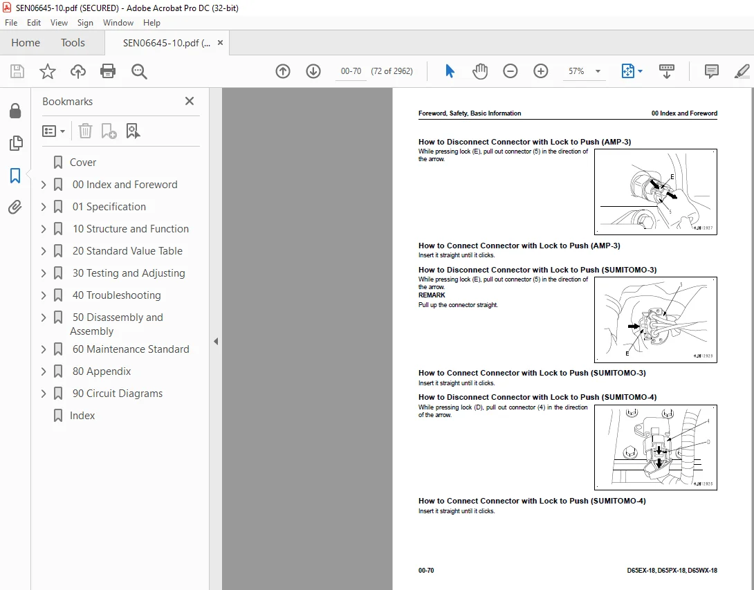
Disconnect and Connect Connector with Lock to Push 71
Disconnect and Connect Connector with Housing to Rotate 73
How to Read the Codes for Electric Cable 74
Explanation of Terms for Maintenance Standard 78
Standard Tightening Torque Table 81
Conversion Table 88
01 Specification 93
Table of Contents 94
Abbreviation List 95
Specifications 101
Specification Drawing 101
Specification Drawing: D65EX-18 101
Specification Drawing: D65PX-18 103
Specification Drawing: D65WX-18 105
Specifications 107
Specifications: D65EX-18 107
Specifications: D65PX-18 115
Specifications: D65WX-18 121
Weight Table 128
Weight Table: D65EX-18 128
Weight Table: D65PX-18 132
Weight Table: D65WX-18 135
Table of Fuel, Coolant, and Lubricants 138
10 Structure and Function 141
Table of Contents 142
Abbreviation List 145
Urea SCR System 151
Layout Drawing of Urea SCR System 151
Urea SCR System Diagram 153
Function of Urea SCR System 154
Function of DEF System 154
Inducement Strategy 157
Component Parts of Urea SCR System 171
DEF Mixing Tube 171
SCR Assembly 171
DEF Tank 174
DEF Pump 176
DEF Injector 177
DEF Hose 178
DEF Tank Heating Valve 179
Boot-up System 180
Layout Drawing of Boot-up System (Machine with KOMTRAX Terminal) 180
System Operating Lamp System 182
System Diagram of System Operating Lamp System 182
Function of Operation Lamp System 182
Battery Disconnect Switch 184
Layout Drawing of Battery Disconnect Switch 184
Function of Battery Disconnect Switch 184
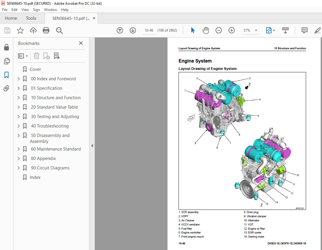
Engine System 186
Layout Drawing of Engine System 186
Engine Control System 188
Layout of Engine Control System (Machine with KOMTRAX Terminal) 188
System Diagram of Engine Control System (Machine with KOMTRAX Terminal) 189
Function of Engine Control System (Machine with KOMTRAX Terminal) 191
Automatic Idle Stop System 193
System Diagram of Automatic Idle Stop System 193
Function of Automatic Idle Stop System 193
Component Parts of Engine System 196
Damper 196
VGT 197
EGR System 201
EGR Valve 203
EGR Cooler 205
KCCV System 206
KCCV Ventilator 208
KDPF 210
Cooling System 215
Layout Drawing of Cooling System 215
Specifications of Cooling System 216
Cooling Fan Control System 217
System Diagram of Cooling Fan Control System 217
Function of Cooling Fan Control System 218
Component Parts of Cooling System 220
Cooling Fan Pump 220
Cooling Fan Motor 229
Hydraulic Oil Cooler Bypass Valve 236
Control System 237
Layout Drawing of Control System (Machine with KOMTRAX Terminal) 237
Machine Monitor System 238
System Diagram of Machine Monitor System 238
Function of Machine Monitor System 238
KOMTRAX System 240
System Diagram of KOMTRAX System 240
Function of KOMTRAX System 240
Component Parts of Control System 241
Machine Monitor 241
KOMTRAX Terminal 256
Power Train Controller 258
Engine Controller 262
Hydraulic System 269
Layout Drawing of Hydraulic System 269
CLSS 270
Structure of CLSS 270
Function of CLSS 271
Component Parts of Hydraulic System 273
Hydraulic Tank 273
Work Equipment and HSS Pump 274
LS Valve 279
PC Valve 284
PC-EPC Valve 289
Control Valve 293
Power Train System 324
Layout Drawing of Power Train System 324
Operation of Power Train System 327
Transmission, Steering, and Brake Control 328
Layout Drawing of Transmission, Steering, and Brake Control System 328
Function of Transmission, Steering, and Brake Control 329
Palm Command Control System 330
Palm Command Control System Diagram 330
HSS System 334
HSS System Diagram 334
Function of HSS System 335
Centralized Pressure Pickup Port 337
Layout Drawing of Centralized Pressure Pickup Port 337
Function of Centralized Pressure Pickup Port 337
Component Parts of Power Train System 338
Universal Joint 338
Power Train Mount 339
Torque Converter and PTO 340
Lockup Clutch ECMV 345
Transmission 349
Transmission Control Valve 361
Forward and Reverse Clutch ECMV and Gear Speed Clutch ECMV 362
Main Relief Valve and Torque Converter Relief Valve 367
Transmission Lubrication Relief Valve 369
Bevel Gear Shaft, HSS, and Brake 370
Brake Valve 389
Final Drive 393
Scavenging Pump 396
Steering Lubrication Pump and Power Train Pump 397
HSS Motor 398
Electric Steering Electric Lever 403
Work Equipment System 407
Work Equipment Control 407
Layout Drawing of Work Equipment Control 407
Function of Work Equipment Control 408
Layout of Tilt Dozer, Power Tilt Pitch Dozer and Angle Dozer Series 410
Layout of Power Angle Power Tilt Dozer Series 411
Layout Drawing of Fixed Multi-Shank Ripper 412
Component Parts of Work Equipment System 413
Self-Pressure Reducing Valve 413
Work Equipment Lock Solenoid Valve 419
Blade PPC Valve 423
Ripper PPC Valve 429
Blade Pitch Selector Solenoid Valve 432
Pilot Circuit Accumulator 434
Angle Control EPC Valve 435
Quick Drop Valve 438
Piston Valve 439
Undercarriage and Frame 442
Main Frame 442
Structure of Main Frame 442
Suspension 444
Structure of Suspension 444
Specifications of Suspension 445
Function of Suspension 446
Track Frame and Idler Cushion 447
Structure of Track Frame and Idler Cushion 447
Function of Track Frame and Idler Cushion 449
Work Equipment 450
Structure of Front Work Equipment (For Tilt Dozer and Power Tilt Pitch Dozer Series) 450
Structure of Front Work Equipment (For Power Angle Power Tilt Dozer Series) 451
Structure of Front Work Equipment (Angle Dozer Series) 452
Structure of Fixed Multi-Shank Ripper 453
CAB Related Parts 454
ROPS CAB 454
Structure of ROPS CAB 454
Function of ROPS CAB 455
CAB Mount 456
Structure of CAB Mount 456
Function of CAB Mount 456
20 Standard Value Table 457
Table of Contents 458
Abbreviation List 459
Standard Value Table for Engine 465
Standard Value Table for Engine: D65EX-18 465
Standard Value Table for Engine: D65PX-18 470
Standard Value Table for Engine: D65WX-18 475
Standard Value Table for Machine 480
Standard Value Table for Machine: D65EX-18 480
Standard Value Table for Machine: D65PX-18 495
Standard Value Table for Machine: D65WX-18 510
Machine Posture and Procedures to Measure Performance 525
Standard Value Table for Electricity 527
Standard Value Table for Electricity 527
30 Testing and Adjusting 537
Table of Contents 538
Precautions Before Work 541
Abbreviation List 542
Related Information on Testing and Adjusting 548
Tools for Testing and Adjusting 548
Sketch of Tools for Testing and Adjusting 554
Engine and Cooling System 555
Examine Engine Speed 555
How to Examine Engine Speed 555
Examine Boost Pressure 559
How to Examine Boost Pressure 559
Examine Exhaust Gas Temperature 561
How to Examine Exhaust Gas Temperature 561
Examine Exhaust Gas Color 563
How to Examine Exhaust Gas Color with the Handy Smoke Checker 563
How to Examine Exhaust Gas Color with Smoke Meter 563
Examine Mass Air Flow and Temperature Sensor 565
How to Examine Mass Air Flow and Temperature Sensor 565
Examine and Adjust Valve Clearance 567
Check Valve Clearance 567
Adjust Valve Clearance 568
Examine Compression Pressure 570
How to Examine Compression Pressure 570
Examine Blowby Pressure 572
How to Examine Blowby Pressure 572
Examine Engine Oil Pressure 575
How to Examine Engine Oil Pressure 575
Examine EGR Valve and VGT Oil Pressure 576
How to Examine EGR Valve and VGT Oil Pressure 576
Examine Fuel Pressure 578
How to Examine Fuel Pressure 579
Examine Fuel Discharge, Return and Leakage 585
How to Examine Fuel Discharge, Return, and Leakage 586
Bleed Air from Fuel System 590
How to Bleed Air from Fuel System 590
Examine Fuel Circuit for Leakage 592
How to Examine Fuel System for Leakage 592
Handle Cylinder Cut-out Mode Operation 594
Handle No-Injection Cranking Operation 595
Examine and Adjust Air Conditioner Compressor Belt Tension 596
How to Examine Air Conditioner Compressor Belt Tension 596
How to Adjust Air Conditioner Compressor Belt Tension 596
Examine Alternator Belt 597
How to Examine Alternator Belt 597
Examine Automatic Tensioner 598
How to Examine Automatic Tensioner 598
Write Correction for Ash in Soot Accumulation to Engine Controller 600
How to Write Correction for Ash in Soot Accumulation to Engine Controller 600
Examine SCR Related Functions 601
Examine DEF Pump Raised Pressure 604
Examine Injection Volume from DEF Injector 606
Examine DEF Line Heater Relay 1 611
Examine DEF Line Heater Relay 2 613
Examine DEF Pump Heater Relay 616
Examine DEF Tank Heater Valve 619
Examine SCR Denitration Efficiency 621
Clean DEF Tank 625
How to Clean DEF Tank 625
Clean DEF Tank Mounting Part 629
How to Clean DEF Tank Mounting Part 629
Clean DEF Pump 631
How to Clean DEF Pump 631
Adjust Decelerator Pedal 637
How to Adjust Decelerator Pedal 637
Power Train 639
Examine Power Train Oil Pressure 639
How to Examine Power Train Oil Pressure 640
Adjust Transmission Output Shaft Speed Sensor 651
How to Adjust Transmission Output Shaft Speed Sensor 651
Examine Brake Performance Simply 653
How to Examine Brake Performance Simply 653
Adjust Brake Pedal 654
How to Adjust Brake Pedal 654
Adjust Parking Brake Lever 656
How to Adjust Parking Brake Lever 656
Move Machine by Parking Brake Release When Machine Does Not Travel 658
Move Machine with Hydraulic Type Parking Brake Release System 658
Move Machine with Electric Type Parking Brake Release System 659
Undercarriage and Frame 661
Adjust Idler Clearance 661
How to Adjust Idler Clearance 661
Examine and Adjust Track Tension 662
How to Examine Track Tension 662
How to Adjust Track Tension 662
Hydraulic System 663
Release Remained Pressure in Hydraulic Circuit 663
How to Release Remained Pressure in Hydraulic System 663
Examine and Adjust Work Equipment and HSS Oil Pressure 664
How to Examine Work Equipment and HSS Oil Pressure 664
Adjust Oil Pressure of Work Equipment and HSS 668
Examine Oil Pressure of Control Circuit 669
Examine Oil Pressure in Control Circuit 669
Examine PPC Valve Outlet Pressure 671
Examine Outlet Pressure in PPC Valve 671
Bleed Air from HSS Pump 673
How to Bleed Air from HSS Pump 673
Examine and Adjust Play of Work Equipment PPC Valve 674
How to Examine Play of Work Equipment PPC Valve 674
How to Adjust Play of Work Equipment PPC Valve 675
Examine Cooling Fan Speed 676
How to Examine Cooling Fan Speed 676
Examine Cooling Fan Circuit Oil Pressure 677
How to Examine Cooling Fan Circuit Oil Pressure 677
Bleed Air in Cooling Fan Pump 679
How to Bleed Air in Cooling Fan Pump 679
Examine Parts Which Cause Hydraulic Drift of Work Equipment 680
How to Examine Parts Which Cause Hydraulic Drift of Blade Lift Cylinder 680
How to Examine the Parts Which Cause Hydraulic Drift of Blade Tilt Cylinder 680
How to Examine the Parts Which Cause Hydraulic Drift of Ripper Lift Cylinder 681
Examine Oil Leakage from Work Equipment Cylinder 682
How to Examine Internal Oil Leakage of Work Equipment Cylinder 682
Bleed Air from Work Equipment Cylinders 684
Bleed Air from Work Equipment Cylinder 684
Work Equipment 686
Adjust Work Equipment Lock Lever 686
How to Adjust Work Equipment Lock Lever 686
CAB Related Parts 688
Examine and Adjust Operator Cab 688
Examine Operator Cab 688
Adjust Operator Cab 690
Electrical System 693
Set and Operate Machine Monitor 693
Operator Mode 697
Function to Show Technician Identification Status Screen 697
Function to Show Operator Identification Input Screen 697
Examine Function by LCD (Liquid Crystal Display) 698
Examine Function of Service Meter 698
Usage Limitation and Change Maintenance Password 698
Service Mode 701
How to Operate Service Mode 701
How to See Pre-defined Monitoring Information 702
How to Examine Self-Define Monitor Information 708
Abnormality Record Menu 718
How to See Maintenance Record 722
Maintenance Mode Setting 723
Set Phone Number Entry 727
Default Menu 729
Diagnostic Tests Menu 736
Adjustment Menu 745
No-Injection Cranking Operation 774
KOMTRAX Settings Menu 776
Show Service Message 778
How to Start Up KOMTRAX Terminal 780
Adjust When Power Train Controller is Replaced 785
How to Adjust When Power Train Controller is Replaced 785
Adjust Rearview Camera Angle 788
How to Adjust Rearview Camera Angle 788
Handle Voltage Circuit of Engine Controller 789
Handle Battery Disconnect Switch (Machine with KOMTRAX Terminal) 790
Examine Diodes 791
Examine Diodes by Digital Tester 791
How to Examine Diodes by Analog Tester 791
Pm Clinic 792
Pm Clinic Service 792
Pm Clinic Check Sheet: D65EX-18 793
Pm Clinic Check Sheet: D65PX-18 805
Pm Clinic Check Sheet: D65WX-18 817
Pm Clinic Check Sheet for Undercarriage: D65EX-18 830
Pm Clinic Check Sheet for Undercarriage: D65PX-18 837
Pm Clinic Check Sheet for Undercarriage: D65WX-18 843
40 Troubleshooting 849
Table of Contents 850
Precautions Before Work 860
Abbreviation List 861
Related Information to Troubleshooting 867
General Troubleshooting Points 867
Troubleshooting Points for Urea SCR System 868
Sequence of Events in Troubleshooting 882
Checks Before Troubleshooting 884
Inspection Procedure Before Troubleshooting 886
Walk-Around Check 886
Test in Accordance with Testing Procedure 888
How to Examine Electric Equipment 888
Preparation for Troubleshooting of Electrical System 896
Procedure for Troubleshooting 904
Symptom and Troubleshooting Numbers 907
Information Shown in Troubleshooting Table 910
Diagnose Open Circuit of Hydraulic Pressure Sensor System Wiring Harness 912
Connector List and Layout 914
Connector Contact Connection Table 930
T-Branch Box and T-Branch Adapter Table 970
Fuse Location Table (Machine with KOMTRAX Terminal) 976
Precautions When You Clean and Replace KDPF (KCSF and KDOC) 979
Prepare Short Circuit Electrical Connector (For Failure Codes [CA1883] and [CA3135]) 983
Failure Code Table 985
Troubleshooting by Failure Code (Display of Code)1003
Failure Code [1500L0]1003
Failure Code [15SAL1]1004
Failure Code [15SALH]1006
Failure Code [15SBL1]1008
Failure Code [15SBLH]1010
Failure Code [15SEL1]1012
Failure Code [15SELH]1014
Failure Code [15SFL1]1016
Failure Code [15SFLH]1018
Failure Code [15SGL1]1020
Failure Code [15SGLH]1022
Failure Code [15SJL1]1024
Failure Code [15SJLH]1026
Failure Code [1800MW]1028
Failure Code [879AKA]1029
Failure Code [879AKB]1030
Failure Code [879BKA]1031
Failure Code [879BKB]1033
Failure Code [879CKA]1035
Failure Code [879CKB]1036
Failure Code [879DKZ]1037
Failure Code [879EMC]1039
Failure Code [879FMC]1040
Failure Code [879GKX]1041
Failure Code [989L00]1043
Failure Code [989M00]1044
Failure Code [989N00]1045
Failure Code [A1U0N3]1046
Failure Code [A1U0N4]1048
Failure Code [A900FR]1050
Failure Code [A900N6]1051
Failure Code [A900NY]1052
Failure Code [AA10NX]1053
Failure Code [AB00KE]1055
Failure Code [AQ10N3]1057
Failure Code [AS00N3]1059
Failure Code [AS00R2]1061
Failure Code [AS00R3]1062
Failure Code [AS00R4]1063
Failure Code [AS00R5]1064
Failure Code [AS00R6]1065
Failure Code [AS00ZK]1066
Failure Code [AS10KM]1067
Failure Code [AS10NR]1068
Failure Code [AS10NT]1069
Failure Code [B@BAZG]1070
Failure Code [B@BCNS]1071
Failure Code [B@BCQA]1072
Failure Code [B@BCZK]1074
Failure Code [B@CENS]1076
Failure Code [B@HANS]1077
Failure Code [CA115]1078
Failure Code [CA122]1079
Failure Code [CA123]1081
Failure Code [CA131]1083
Failure Code [CA132]1085
Failure Code [CA144]1088
Failure Code [CA145]1090
Failure Code [CA153]1092
Failure Code [CA154]1095
Failure Code [CA187]1098
Failure Code [CA221]1100
Failure Code [CA222]1102
Failure Code [CA227]1104
Failure Code [CA234]1105
Failure Code [CA238]1106
Failure Code [CA239]1108
Failure Code [CA249]1110
Failure Code [CA256]1112
Failure Code [CA271]1114
Failure Code [CA272]1116
Failure Code [CA281]1118
Failure Code [CA322]1119
Failure Code [CA323]1121
Failure Code [CA324]1123
Failure Code [CA325]1125
Failure Code [CA331]1127
Failure Code [CA332]1129
Failure Code [CA343]1131
Failure Code [CA351]1132
Failure Code [CA352]1133
Failure Code [CA356]1136
Failure Code [CA357]1138
Failure Code [CA386]1140
Failure Code [CA428]1141
Failure Code [CA429]1143
Failure Code [CA435]1145
Failure Code [CA441]1147
Failure Code [CA442]1149
Failure Code [CA449]1150
Failure Code [CA451]1154
Failure Code [CA452]1157
Failure Code [CA488]1159
Failure Code [CA515]1160
Failure Code [CA516]1162
Failure Code [CA553]1164
Failure Code [CA555]1165
Failure Code [CA556]1166
Failure Code [CA559]1167
Failure Code [CA595]1171
Failure Code [CA687]1172
Failure Code [CA689]1174
Failure Code [CA691]1179
Failure Code [CA692]1181
Failure Code [CA697]1183
Failure Code [CA698]1184
Failure Code [CA731]1185
Failure Code [CA778]1187
Failure Code [CA1117]1192
Failure Code [CA1664]1193
Failure Code [CA1669]1196
Failure Code [CA1673]1197
Failure Code [CA1677]1198
Failure Code [CA1678]1199
Failure Code [CA1682]1200
Failure Code [CA1683]1205
Failure Code [CA1684]1207
Failure Code [CA1686]1209
Failure Code [CA1691]1210
Failure Code [CA1694]1213
Failure Code [CA1695]1216
Failure Code [CA1696]1217
Failure Code [CA1712]1219
Failure Code [CA1713]1222
Failure Code [CA1714]1224
Failure Code [CA1715]1225
Failure Code [CA1776]1226
Failure Code [CA1777]1229
Failure Code [CA1843]1232
Failure Code [CA1844]1234
Failure Code [CA1879]1237
Failure Code [CA1881]1240
Failure Code [CA1883]1243
Failure Code [CA1885]1247
Failure Code [CA1887]1249
Failure Code [CA1921]1251
Failure Code [CA1922]1254
Failure Code [CA1942]1259
Failure Code [CA1993]1260
Failure Code [CA2185]1263
Failure Code [CA2186]1265
Failure Code [CA2249]1267
Failure Code [CA2265]1268
Failure Code [CA2266]1270
Failure Code [CA2271]1272
Failure Code [CA2272]1275
Failure Code [CA2288]1278
Failure Code [CA2311]1279
Failure Code [CA2349]1280
Failure Code [CA2353]1283
Failure Code [CA2357]1285
Failure Code [CA2381]1286
Failure Code [CA2382]1289
Failure Code [CA2383]1292
Failure Code [CA2386]1295
Failure Code [CA2387]1297
Troubleshooting Flowchart1301
Failure Code [CA2555]1302
Failure Code [CA2556]1305
Failure Code [CA2637]1308
Failure Code [CA2639]1310
Failure Code [CA2771]1313
Failure Code [CA2777]1319
Failure Code [CA2976]1322
Failure Code [CA3133]1324
Failure Code [CA3134]1326
Failure Code [CA3135]1328
Failure Code [CA3142]1332
Failure Code [CA3143]1333
Failure Code [CA3144]1334
Failure Code [CA3146]1336
Failure Code [CA3147]1337
Failure Code [CA3148]1338
Failure Code [CA3151]1340
Failure Code [CA3165]1346
Failure Code [CA3229]1348
Failure Code [CA3231]1350
Failure Code [CA3232]1352
Failure Code [CA3235]1356
Failure Code [CA3239]1358
Failure Code [CA3241]1361
Failure Code [CA3242]1364
Failure Code [CA3251]1367
Failure Code [CA3253]1369
Failure Code [CA3254]1372
Failure Code [CA3255]1375
Failure Code [CA3256]1378
Failure Code [CA3311]1380
Failure Code [CA3312]1382
Failure Code [CA3313]1385
Failure Code [CA3314]1386
Failure Code [CA3315]1387
Failure Code [CA3316]1390
Failure Code [CA3317]1391
Failure Code [CA3318]1392
Failure Code [CA3319]1395
Failure Code [CA3321]1396
Failure Code [CA3322]1398
Failure Code [CA3419]1401
Failure Code [CA3421]1403
Failure Code [CA3497]1405
Failure Code [CA3498]1406
Failure Code [CA3543]1407
Failure Code [CA3545]1414
Failure Code [CA3547]1416
Failure Code [CA3558]1417
Failure Code [CA3559]1419
Failure Code [CA3562]1421
Failure Code [CA3563]1423
Failure Code [CA3567]1426
Failure Code [CA3568]1429
Failure Code [CA3571]1436
Failure Code [CA3572]1438
Failure Code [CA3574]1440
Failure Code [CA3575]1443
Failure Code [CA3577]1445
Failure Code [CA3578]1447
Failure Code [CA3582]1449
Failure Code [CA3583]1458
Failure Code [CA3596]1460
Failure Code [CA3649]1463
Failure Code [CA3681]1465
Failure Code [CA3682]1467
Failure Code [CA3713]1470
Failure Code [CA3717]1473
Failure Code [CA3718]1474
Failure Code [CA3725]1475
Failure Code [CA3741]1478
Failure Code [CA3748]1479
Failure Code [CA3751]1482
Failure Code [CA3755]1484
Failure Code [CA3866]1486
Failure Code [CA3867]1490
Failure Code [CA3868]1493
Failure Code [CA3899]1497
Failure Code [CA3911]1499
Failure Code [CA3912]1503
Failure Code [CA3932]1505
Failure Code [CA3933]1507
Failure Code [CA3934]1509
Failure Code [CA3935]1512
Failure Code [CA3936]1514
Failure Code [CA4151]1516
Failure Code [CA4152]1520
Failure Code [CA4155]1524
Failure Code [CA4156]1527
Failure Code [CA4157]1530
Failure Code [CA4158]1532
Failure Code [CA4159]1533
Failure Code [CA4161]1534
Failure Code [CA4162]1536
Failure Code [CA4163]1539
Failure Code [CA4164]1541
Failure Code [CA4165]1543
Failure Code [CA4166]1545
Failure Code [CA4168]1547
Failure Code [CA4169]1550
Failure Code [CA4171]1552
Failure Code [CA4249]1555
Failure Code [CA4251]1557
Failure Code [CA4259]1559
Failure Code [CA4261]1562
Failure Code [CA4277]1565
Failure Code [CA4281]1569
Failure Code [CA4459]1573
Failure Code [CA4461]1576
Failure Code [CA4658]1579
Failure Code [CA4731]1583
Failure Code [CA4732]1584
Failure Code [CA4739]1585
Failure Code [CA4768]1586
Failure Code [CA4769]1588
Failure Code [CA4842]1591
Failure Code [CA4952]1595
Failure Code [CA5115]1597
Failure Code [CA5383]1600
Failure Code [D130KA]1602
Failure Code [D130KB]1605
Failure Code [D19JKZ]1607
Failure Code [D811MC]1610
Failure Code [D862KA]1611
Failure Code [D8ALKA]1612
Failure Code [D8ALKB]1614
Failure Code [D8AQKR]1616
Failure Code [DAF0MB]1618
Failure Code [DAF0MC]1619
Failure Code [DAF8KB]1620
Failure Code [DAF9KQ]1621
Failure Code [DAFGMC]1622
Failure Code [DAFLKA]1623
Failure Code [DAFLKB]1625
Failure Code [DAFQKR]1627
Failure Code [DAQW00]1628
Failure Code [DAZ9KQ]1629
Failure Code [DAZQKR]1630
Failure Code [DB2QKR]1631
Failure Code [DB2RKR]1636
Failure Code [DBE0KT]1641
Failure Code [DBE1KK]1642
Failure Code [DBE2KK]1645
Failure Code [DBE5KK]1648
Failure Code [DBE6KK]1650
Failure Code [DBE7KK]1652
Failure Code [DBE9KQ]1654
Failure Code [DBELKA]1655
Failure Code [DBELKB]1657
Failure Code [DBEQKR]1659
Failure Code [DBERKR]1660
Failure Code [DD12KA]1662
Failure Code [DD12KB]1664
Failure Code [DD13KA]1666
Failure Code [DD13KB]1668
Failure Code [DD14KA]1670
Failure Code [DD14KB]1672
Failure Code [DDKFL4]1674
Failure Code [DDKGL4]1676
Failure Code [DDKHKA]1678
Failure Code [DDKHKB]1680
Failure Code [DDN7KA]1682
Failure Code [DDN7KB]1684
Failure Code [DDNLKA]1686
Failure Code [DDNLKB]1688
Failure Code [DGS1KA]1690
Failure Code [DGS1KX]1692
Failure Code [DGT1KA]1694
Failure Code [DGT1KX]1697
Failure Code [DH21KA]1699
Failure Code [DH21KY]1701
Failure Code [DHA4KA]1703
Failure Code [DHAAMA]1705
Failure Code [DHACMA]1707
Failure Code [DHTDKA]1709
Failure Code [DHTDKY]1711
Failure Code [DK10KA]1713
Failure Code [DK10KB]1716
Failure Code [DK30KA]1718
Failure Code [DK30KX]1721
Failure Code [DK30KY]1722
Failure Code [DK30KZ]1724
Failure Code [DK30L8]1725
Failure Code [DK31KA]1726
Failure Code [DK31KY]1729
Failure Code [DK40KA]1731
Failure Code [DK40KY]1733
Failure Code [DK55KX]1735
Failure Code [DK55KZ]1736
Failure Code [DK55L8]1737
Failure Code [DK56KA]1738
Failure Code [DK56KY]1740
Failure Code [DK57KA]1742
Failure Code [DK57KY]1744
Failure Code [DKH1KA]1746
Failure Code [DKH1KY]1749
Failure Code [DLM3KA]1751
Failure Code [DLM3MB]1753
Failure Code [DLT3KA]1754
Failure Code [DLT3KB]1756
Failure Code [DR21KX]1758
Failure Code [DR31KX]1759
Failure Code [DV20KB]1760
Failure Code [DW5AKA]1762
Failure Code [DW5AKB]1764
Failure Code [DW5AKY]1766
Failure Code [DW7BKA]1768
Failure Code [DW7BKB]1770
Failure Code [DW7BKY]1772
Failure Code [DWN1KA]1773
Failure Code [DWN1KB]1775
Failure Code [DWN1KY]1777
Failure Code [DWN2KA]1779
Failure Code [DWN2KB]1781
Failure Code [DWN2KY]1783
Failure Code [DWN5KA]1784
Failure Code [DWN5KB]1786
Failure Code [DWN5KY]1787
Failure Code [DXA2KA]1789
Failure Code [DXA2KB]1791
Failure Code [DXA2KY]1793
Failure Code [DXH1KA]1794
Failure Code [DXH1KB]1796
Failure Code [DXH1KY]1798
Failure Code [DXH4KA]1800
Failure Code [DXH4KB]1802
Failure Code [DXH4KY]1804
Failure Code [DXH5KA]1806
Failure Code [DXH5KB]1808
Failure Code [DXH5KY]1810
Failure Code [DXH6KA]1812
Failure Code [DXH6KB]1814
Failure Code [DXH6KY]1816
Failure Code [DXH7KA]1818
Failure Code [DXH7KB]1820
Failure Code [DXH7KY]1822
Failure Code [DXH8KA]1824
Failure Code [DXH8KB]1826
Failure Code [DXH8KY]1828
Failure Code [DXJ4KA]1830
Failure Code [DXJ4KB]1832
Failure Code [DXJCKA]1834
Failure Code [DXJCKB]1836
Failure Code [DXJCKY]1838
Failure Code [DXJDKA]1840
Failure Code [DXJDKB]1842
Failure Code [DXJDKY]1844
Troubleshooting of Electrical System (E-Mode)1846
Engine Does Not Start (Engine Does Not Crank)1846
Manual Preheating System Does Not Operate1853
Automatic Preheating System Does Not Operate1856
While Preheating is in Operation, Preheating Monitor Does Not Come On1858
When Starting Switch is Turned to ON Position, Machine Monitor Shows Nothing1860
When Starting Switch is Turned to ON Position (with Engine Stopped), Basic Check Monitor Comes On1864
Air Cleaner Clogging Monitor Comes On in Yellow While Engine is in Operation1865
Charge Level Monitor Comes On in Red While Engine is in Operation1866
Engine Coolant Temperature Monitor Comes On in Red While Engine is in Operation1868
Engine Oil Pressure Monitor Comes On in Red While Engine is in Operation1869
Power Train Oil Temperature Monitor Comes On in Red While Engine Runs1870
Hydraulic Oil Temperature Monitor Comes On in Red While Engine is in Operation1871
Engine Coolant Temperature Gauge Does Not Show Correct Temperature1872
DEF Level is Not Shown Correctly1873
Fuel Gauge Does Not Show Normally1876
Power Train Oil Temperature Gauge Does Not Show Correct Temperature1878
Hydraulic Oil Temperature Gauge Does Not Show Correct Temperature1879
Operation Mode Does Not Change1880
Gear Shift Mode Does Not Change1881
When You Operate Customize Switch Does Not Show Customize Screen1882
When You Change Setting on Customize Screen, Setting of Machine is Not Changed1883
Some Areas of Machine Monitor Screen are Not Shown1884
REVERSE Slow Mode Function Does Not Operate Correctly1885
Alarm Buzzer Does Not Operate or Does Not Stop Operation1886
Service Meter is Not Shown While Starting Switch is in OFF Position1887
Service Mode Cannot be Selected1888
Horn Does Not Sound1889
Horn Does Not Stop1891
Backup Alarm Does Not Sound1892
Backup Alarm Does Not Stop Operation1894
Headlamp Does Not Come On1895
Rear Lamp Does Not Come On1899
No Wiper Operates1902
Front Wiper Does Not Operate1906
Rear Wiper Does Not Operate1909
Left Door Wiper Does Not Operate1912
Right Door Wiper Does Not Operate1915
Front Washer Does Not Operate1918
Rear Washer Does Not Operate1920
Left Door Washer Does Not Operate1922
Right Door Washer Does Not Operate1924
KOMTRAX System Does Not Operate Correctly1926
Troubleshooting for Hydraulic and Mechanical Systems (H Mode)1927
Information Shown in Troubleshooting Table (H-Mode)1927
System Chart of Hydraulic and Mechanical Systems1928
Failure Mode and Cause Table1930
Machine Lacks Power (Drawbar Pull is Not Sufficient)1938
Machine Does Not Travel (at 2nd or 3rd Gear Speed)1940
Machine Does Not Move Off at All Gear Speeds1941
Machine Travels Only in One Direction, Forward or in Reverse1943
Large Time Lag is in Gear Shifting or Directional Change1944
Brake Does Not Work1946
Power Train Oil Overheats1947
Unusual Noise is Heard from Around Work Equipment and HSS Pump or HSS Motor1949
Torque Converter Lockup Clutch Does Not Engage1950
Machine Cannot be Steered (Machine Does Not Turn Left or Right)1951
Steering Speed or Power is Not Sufficient1952
All Work Equipment Operate Slowly1953
All Work Equipment Do Not Operate1954
Blade Lift Speed or Power is Low1955
Blade Tilt Speed or Power is Low1956
Blade Angle Speed or Power is Low1957
Ripper Lift Speed or Power is Low1958
Hydraulic Drift of Blade Lift is Large1959
Hydraulic Drift of Tilted Blade is Large1960
Hydraulic Drift of Lifted Ripper is Large1961
Fan Speed is Abnormal (Too High or Low, or Does Not Rotate)1962
Unusual Noise is Heard from Around Fan1964
Troubleshooting of Engine (S-Mode)1965
Information Shown in Troubleshooting Table (S-Mode)1965
Engine Does Not Crank When Starting Switch is Turned to Start Position1966
Engine Cranks but No Exhaust Smoke Comes Out1967
Fuel is Sprayed but Engine Does Not Start (Misfiring: Engine Cranks but Does Not Start)1968
Engine Startability is Unsatisfactory1970
Engine Does Not Pick Up Smoothly1972
Engine Stops During Operation1974
Engine Does Not Rotate Smoothly1976
Engine Lacks Output (or Lacks Power)1977
KDPF Becomes Clogged in a Short Time1979
Engine Oil Consumption is Excessive1981
Engine Oil Becomes Dirty Quickly1982
Fuel Consumption is Excessive1983
Oil is in Coolant (or Coolant Spurts Back or Coolant Level Goes Down)1984
Engine Oil Pressure Drops1985
Fuel Mixes Into Engine Oil1987
Water Mixes Into Engine Oil (Milky)1988
Coolant Temperature Increases Too High (Overheat)1989
Unusual Noise is Heard1990
Vibration is Excessive1991
Air Cannot be Bled from Fuel Circuit1992
Active Regeneration is Done Frequently1993
Active Regeneration Continues Long1995
White Smoke is Exhausted During Active Regeneration1996
DEF Consumption is Excessive1997
There is an Unusual Smell (Irritating Odor)1999
Foreign Materials Enter DEF (DEF Increases)2000
50 Disassembly and Assembly2001
Table of Contents2002
Precautions Before Work2007
Abbreviation List2008
Related Information on Disassembly and Assembly2014
How to Read This Manual2014
Coating Materials List2015
Special Tool List2020
Sketches of Special Tools2041
Engine and Cooling System2062
Remove and Install Supply Pump Assembly2062
Remove Supply Pump Assembly2062
Install Supply Pump Assembly2066
Remove and Install Injector Assembly2071
How to Remove Injector Assembly2072
How to Install Injector Assembly2079
Remove and Install Cylinder Head Assembly2090
How to Remove Cylinder Head Assembly2091
How to Install Cylinder Head Assembly2101
Remove and Install EGR Valve Assembly2117
Remove EGR Valve Assembly2117
Install EGR Valve Assembly2118
Remove and Install EGR Cooler Assembly2119
How to Remove EGR Cooler Assembly2119
How to Install EGR Cooler Assembly2120
Remove and Install Starter Assembly2122
Remove Starting Motor Assembly2122
Install Starting Motor Assembly2124
Remove and Install Alternator Belt2127
Remove Alternator Belt2127
Install Alternator Belt2128
Remove and Install Automatic Tensioner2130
Remove Automatic Tensioner2130
Install Automatic Tensioner2130
Remove and Install Radiator Assembly2131
How to Remove Radiator Assembly2131
How to Install Radiator Assembly2134
Remove and Install Hydraulic Oil Cooler Assembly2138
How to Remove Hydraulic Oil Cooler Assembly2138
How to Install Hydraulic Oil Cooler Assembly2140
Remove and Install Aftercooler Assembly2143
Remove Aftercooler Assembly2143
Install Aftercooler Assembly2145
Remove and Install Power Train Oil Cooler Assembly2148
How to Remove Power Train Oil Cooler Assembly2148
How to Install Power Train Oil Cooler Assembly2150
Remove and Install Cooling Fan Drive Assembly2153
Remove Cooling Fan Drive Assembly2153
Install Cooling Fan Drive Assembly2154
Remove and Install Cooling Fan Motor Assembly2157
Remove Cooling Fan Motor Assembly2157
Install Cooling Fan Motor Assembly2159
Remove and Install Engine Assembly2161
Remove Engine Assembly2161
Install Engine Assembly2165
Remove and Install Engine Front Oil Seal2171
How to Remove Engine Front Oil Seal2171
How to Install Engine Front Oil Seal2173
Remove and Install Engine Rear Oil Seal2177
How to Remove Engine Rear Oil Seal2177
How to Install Engine Rear Oil Seal2181
Remove and Install Engine Hood Assembly2189
How to Remove Engine Hood Assembly2189
How to Install Engine Hood Assembly2192
Remove and Install Fuel Tank Assembly2195
Remove Fuel Tank Assembly2195
Install Fuel Tank Assembly2197
Remove and Install DEF Tank Assembly2199
How to Remove DEF Tank Assembly2200
How to Install DEF Tank Assembly2204
Remove and Install DEF Tank Sensor Flange Assembly2208
How to Remove DEF Tank Sensor Flange Assembly2209
How to Install DEF Tank Sensor Flange Assembly2214
Remove and Install DEF Tank Sensor2220
Remove DEF Tank Sensor2220
Install DEF Tank Sensor2221
Remove and Install DEF Tank Strainer2228
Remove DEF Tank Strainer2228
Install DEF Tank Strainer2228
Remove and Install KDPF Assembly2229
How to Remove KDPF Assembly2229
How to Install KDPF Assembly2233
Disassemble and Assemble KDPF Assembly2237
Disassemble KDPF Assembly2237
Assemble KDPF Assembly2241
Remove and Install SCR Assembly2247
How to Remove SCR Assembly2247
How to Install SCR Assembly2249
Remove and Install KDPF and SCR Assembly2252
How to Remove KDPF and SCR Assembly2252
Install KDPF and SCR Assembly2259
Remove and Install KCCV Assembly2266
Remove KCCV Assembly2266
Install KCCV Assembly2268
Remove and Install DEF Mixing Tube2270
Remove DEF Mixing Tube2270
Install DEF Mixing Tube2273
Remove and Install DEF Injector2278
Remove DEF Injector2278
Install DEF Injector2281
Remove and Install DEF Pump2285
Remove DEF Pump2285
Install DEF Pump2288
Remove and Install DEF Hose2291
Remove DEF Hose2291
Install DEF Hose2296
Remove and Install Air Cleaner Assembly2301
Remove Air Cleaner Assembly2301
Install Air Cleaner Assembly2302
Remove and Install Air Conditioner Compressor Assembly2304
Remove Air Conditioner Compressor Assembly2304
How to Install Air Conditioner Compressor Assembly2306
Remove and Install Air Conditioner Condenser Assembly2309
How to Remove Air Conditioner Condenser Assembly2309
How to Install Air Conditioner Condenser Assembly2311
Power Train2313
Remove and Install Damper Assembly2313
How to Remove Damper Assembly2313
How to Install Damper Assembly2316
Remove and Install Power Train Unit Assembly2321
Remove Power Train Unit Assembly2321
How to Install Power Train Unit Assembly2326
Disconnect and Connect Power Train Unit Assembly2332
How to Disconnect Power Train Unit Assembly2332
Connect Power Train Unit Assembly2337
Disassemble and Assemble PTO Assembly2343
Disassemble PTO Assembly2343
Assemble PTO Assembly2346
Disassemble and Assemble Torque Converter Assembly2350
Disassemble Torque Converter Assembly2351
Assemble Torque Converter Assembly2357
Disassemble and Assemble Transmission Assembly2366
Disassemble Transmission Assembly2367
Assemble Transmission Assembly2385
Disassemble and Assemble HSS Assembly2398
Disassemble HSS Assembly2400
Assemble HSS Assembly2411
Remove and Install HSS Motor Assembly2428
Remove HSS Motor Assembly2428
How to Install HSS Motor Assembly2430
Remove and Install Final Drive Assembly2433
Remove Final Drive Assembly2433
Install Final Drive Assembly2436
Disassemble and Assemble Final Drive Assembly2439
Disassemble Final Drive Assembly2441
Assemble Final Drive Assembly2448
Undercarriage and Frame2458
Remove and Install Track Frame Assembly2458
Remove Track Frame Assembly2458
Install Track Frame Assembly2460
Remove and Install Idler Assembly2463
Remove Idler Assembly2463
Install Idler Assembly2464
Disassemble and Assemble Idler Assembly2466
Disassemble Idler Assembly2466
Assemble Idler Assembly2468
Remove and Install Recoil Spring Assembly2472
Remove Recoil Spring Assembly2472
Install Recoil Spring Assembly2472
Disassemble and Assemble Recoil Spring Assembly2474
Disassemble Recoil Spring Assembly2474
Assemble Recoil Spring Assembly2477
Remove and Install Track Roller Assembly2480
Remove Track Roller Assembly2480
Install Track Roller Assembly2481
Disassemble and Assemble Track Roller Assembly2482
Disassemble Track Roller Assembly2482
Assemble Track Roller Assembly2484
Remove and Install Carrier Roller Assembly2487
Remove Carrier Roller Assembly2487
Install Carrier Roller Assembly2488
Disassemble and Assemble Carrier Roller Assembly2489
Disassemble Carrier Roller Assembly2489
Assemble Carrier Roller Assembly2490
Remove and Install Pivot Shaft Assembly2493
Remove Pivot Shaft Assembly2493
Install Pivot Shaft Assembly2494
Separate and Connect Track Assembly2495
Examine Before Separation of Track Assembly2495
Separate Track Assembly (Standard)2495
How to Separate Track Assembly (When Track Frame Has Internal Defect)2496
Install Track Assembly2497
Separate and Connect PLUS Type Track Assembly2500
Separate PLUS Type Track Assembly Generally2500
Install PLUS Type Track Assembly2500
Disassemble and Assemble Track Assembly Generally2501
How to Disassemble Full Track Shoes Assembly2501
How to Assemble Full Track Shoes Assembly2504
Disassemble and Assemble PLUS Type Track Assembly Generally2516
Disassemble PLUS Type Track Assembly Generally2517
How to Assemble PLUS Type Track Shoes Assembly Generally2518
Disassemble and Assemble One Track Link Assembly in Field (Track Assembly)2533
Disassemble One Track Link Assembly in Field (Track Assembly)2534
Assemble One Track Link Assembly in Field (Track Assembly)2535
Disassemble and Assemble One Track Link Assembly in Field (PLUS Type Track Assembly)2542
Disassemble One Track Link Assembly in Field (PLUS Type Track Assembly)2543
Assemble One Track Link Assembly in Field (PLUS Type Track Assembly)2545
Remove and Install Equalizer Bar Assembly2549
Remove Equalizer Bar Assembly2549
Install Equalizer Bar Assembly2550
Disassemble and Assemble Equalizer Bar Bushing2552
Disassemble Equalizer Bar Bushing2552
Assemble Equalizer Bar Bushing2552
Hydraulic System2554
Remove and Install Hydraulic Tank Assembly2554
Remove Hydraulic Tank Assembly2554
How to Install Hydraulic Tank Assembly2557
Remove and Install HSS Pump and Cooling Fan Pump Assembly2562
How to Remove HSS Pump and Cooling Fan Pump Assembly2562
How to Install HSS Pump and Cooling Fan Pump Assembly2563
Remove and Install Power Train Pump and Steering Lubrication Pump Assembly2566
Remove Power Train Pump and Steering Lubrication Pump Assembly2566
Install Power Train Pump and Steering Lubrication Pump Assembly2568
Remove and Install Scavenging Pump Assembly2571
Remove Scavenging Pump Assembly2571
Install Scavenging Pump Assembly2571
Remove and Install 5 Spool Control Valve Assembly2573
How to Remove 5 Spool Control Valve Assembly2573
How to Install 5 Spool Control Valve Assembly2575
Remove and Install 4 Spool Control Valve Assembly2578
How to Remove 4 Spool Control Valve Assembly2578
How to Install 4 Spool Control Valve Assembly2580
Disassemble and Assemble Blade PPC Valve2584
How to Disassemble Blade PPC Valve2584
How to Assemble Blade PPC Valve2584
Disassemble and Assemble Ripper PPC Valve2586
How to Disassemble Ripper PPC Valve2586
How to Assemble Ripper PPC Valve2586
Work Equipment2588
Remove and Install Straight Tilt Power Pitch Dozer Blade Assembly2588
How to Remove Straight Tilt Power Pitch Dozer Blade Assembly2588
How to Install Straight Tilt Power Pitch Dozer Blade Assembly2590
Remove and Install Power Angle Power Tilt Dozer Blade Assembly2594
How to Remove Power Angle Power Tilt Dozer Blade Assembly2594
How to Install Power Angle Power Tilt Dozer Blade Assembly2596
Remove and Install Ripper Assembly2599
Remove Ripper Assembly2599
Install Ripper Assembly2602
How to Disassemble and Assemble Work Equipment Cylinder Assembly2605
How to Disassemble Work Equipment Cylinder Assembly2606
How to Assemble Work Equipment Cylinder Assembly2609
CAB Related Parts2614
Remove and Install Operator Cab Assembly2614
How to Remove Operator Cab Assembly2614
Install Operator CAB Assembly2621
Remove and Install Operator Cab Glass (Adhered Glass)2630
Remove Operator CAB Glass (Adhered Glass)2630
Install Operator CAB Glass (Adhered Glass)2631
Remove and Install Air Conditioner Unit Assembly2636
Remove Air Conditioner Unit Assembly2636
Install Air Conditioner Unit Assembly2641
Remove and Install Operator Seat2647
Remove Operator’s Seat2647
Install Operator’s Seat2649
How to Remove and Install Seat Belt2651
How to Remove Seat Belt2651
How to Install Seatbelt2652
Electrical System2653
Remove and Install Engine Controller Assembly2653
Remove Engine Controller Assembly2653
Install Engine Controller Assembly2654
Remove and Install Power Train Controller Assembly2657
Remove Power Train Controller Assembly2657
Install Power Train Controller Assembly2658
Remove and Install Machine Monitor Assembly2660
Remove Machine Monitor Assembly2660
Install Machine Monitor Assembly2661
Remove and Install Mass Air Flow and Temperature Sensor2663
How to Remove Mass Air Flow and Temperature Sensor2663
How to Install Mass Air Flow and Temperature Sensor2664
Remove and Install KCCV Crankcase Pressure Sensor2665
How to Remove KCCV Crankcase Pressure Sensor2665
How to Install KCCV Crankcase Pressure Sensor2666
Remove and Install SCR Temperature Sensor2667
Remove SCR Temperature Sensor2667
Install SCR Temperature Sensor2669
Remove and Install Rearview Camera2671
Remove Rearview Camera2671
Install Rearview Camera2671
Remove and Install KOMTRAX Terminal Assembly2673
Remove KOMTRAX Terminal Assembly2673
Install KOMTRAX Terminal Assembly2675
60 Maintenance Standard2677
Table of Contents2678
Abbreviation List2680
Engine and Cooling System2686
Maintenance Standard for Engine Mount2686
Maintenance Standard for Damper2687
Maintenance Standard for Cooling System2689
Maintenance Standard for Cooling Fan Pump2691
Maintenance Standard for Servo Valve2692
Maintenance Standard for Cooling Fan Motor2693
Power Train2695
Maintenance Standard for Universal Joint2695
Maintenance Standard for Power Train Mount2696
Maintenance Standard for Torque Converter and PTO2698
Maintenance Standard for Lockup Clutch ECMV2701
Maintenance Standard for Transmission2702
Maintenance Standard for Transmission Control Valve2707
Maintenance Standard for Forward and Reverse Clutch ECMV and Gear Speed Clutch ECMV2708
Maintenance Standard for Main Relief Valve and Torque Converter Relief Valve2709
Maintenance Standard for Transmission Lubrication Relief Valve2710
Maintenance Standard for Bevel Gear Shaft, HSS, and Brake2711
Maintenance Standard for Brake Valve2716
Maintenance Standard for Final Drive2718
Maintenance Standard for Sprocket for Conventional Type Track Shoes2721
Maintenance Standard for Sprocket Tooth Profile Full-Scale Drawing for Conventional Type Track Shoes2722
Maintenance Standard for Sprocket for PLUS Type Track Shoes2724
Maintenance Standard for Sprocket Tooth Profile Full-Scale Drawing for PLUS Type Track Shoes2725
Undercarriage and Frame2727
Maintenance Standard for Main Frame2727
Maintenance Standard for Suspension2728
Maintenance Standard for Track Frame and Idler Cushion2730
Maintenance Standard for Idler2732
Maintenance Standard for Track Roller for PLUS Type Track Shoes (Single Flange Type)2734
Maintenance Standard for Track Roller for PLUS Type Track Shoes (Double Flange Type)2735
Maintenance Standard for Carrier Roller for PLUS Type Track Shoes2736
Maintenance Standard for PLUS Type Track Shoes2737
Maintenance Standard for Single Shoes2739
Maintenance Standard for Swamp Shoes2740
Hydraulic System2741
Maintenance Standard for Hydraulic Tank2741
Maintenance Standard for Scavenging Pump2742
Maintenance Standard for Steering Lubrication Pump and Power Train Pump2743
Maintenance Standard for Work Equipment and HSS Pump2744
Maintenance Standard for PC-EPC Valve2745
Maintenance Standard for HSS Motor2746
Maintenance Standard for Control Valve2748
Maintenance Standard for Blade PPC Valve2756
Maintenance Standard for Ripper PPC Valve2758
Maintenance Standard for Angle Control EPC Valve2760
Maintenance Standard for Quick Drop Valve2761
Maintenance Standard for Work Equipment Lock Solenoid Valve (For Tilt Dozer and Angle Dozer Series)2763
Maintenance Standard for Work Equipment Lock Solenoid Valve (For Power Tilt Pitch Dozer Series)2764
Maintenance Standard for Work Equipment Lock Solenoid Valve (For Power Angle Power Tilt Dozer Series)2765
Work Equipment2766
Maintenance Standard for Front Work Equipment (For Tilt Dozer and Power Tilt Pitch Dozer Series)2766
Maintenance Standard for Front Work Equipment (For Power Angle Power Tilt Dozer Series)2769
Maintenance Standard for Front Work Equipment (Angle Dozer Series)2772
Maintenance Standard for Cutting Edge and End Bit2775
Maintenance Standard for Blade Lift Cylinder (For Tilt Dozer and Power Tilt Pitch Dozer, and Angle Dozer Series)2777
Maintenance Standard for Blade Lift Cylinder (For Power Angle Power Tilt Dozer Series)2778
Maintenance Standard for Blade Tilt Cylinder (For Tilt Dozer and Power Tilt Pitch Dozer, and Angle Dozer Series)2779
Maintenance Standard for Blade Tilt Cylinder (For Power Angle Power Tilt Dozer Series)2780
Maintenance Standard for Blade Pitch Cylinder (For Power Tilt Pitch Dozer Series)2781
Maintenance Standard for Blade Angle Cylinder (For Power Angle Power Tilt Dozer Series)2782
Maintenance Standard for Fixed Multi-Shank Ripper2783
Maintenance Standard for Ripper Lift Cylinder2784
CAB Related Parts2785
Maintenance Standard for CAB Mount2785
80 Appendix2787
Table of Contents2788
Precautions Before Work2790
Abbreviation List2791
Air Conditioner System2797
Precautions for Refrigerant2797
Air Conditioner Component2798
Specifications of Air Conditioner2800
Structure and Function of Refrigeration Cycle2801
Outline of Refrigeration Cycle2802
Component Parts of Air Conditioner System2804
Air Conditioner Unit2804
Configuration Diagram of Air Conditioner Unit2804
Function of Air Conditioner Unit2806
Component Parts of Air Conditioner Unit2808
Function of Evaporator as Air Conditioner Unit Component2809
Function of Heater Core as Air Conditioner Unit Component2809
Function of Evaporator Temperature Sensor as Air Conditioner Unit Component2809
Function of Servo Motor as Air Conditioner Unit Component2809
Structure of Expansion Valve as Air Conditioner Unit Component2810
Function of Expansion Valve as Air Conditioner Unit Component2810
Operate Expansion Valve as Air Conditioner Unit Component2810
Function of Dual Pressure Switch2811
Air Conditioner Controller2812
Structure of Air Conditioner Controller2812
Compressor2813
Structure of Compressor2813
Specifications of Compressor2813
Function of Compressor2813
Condenser2814
Structure of Standard Core Condenser2814
Specifications of Standard Core Condenser2814
Function of Standard Core Condenser2814
Structure of Wide Core Condenser2815
Specifications of Wide Core Condenser2815
Function of Wide Core Condenser2815
Receiver Drier2816
Structure of Receiver Dryer2816
Specifications of Receiver Dryer2816
Function of Receiver Dryer2816
Air Conditioner Related Sensors2817
Structure of Sunlight Sensor2817
Function of Sunlight Sensor2817
Structure of Outside Temperature Sensor2817
Function of Outside Air Temperature Sensor2817
Explanation of Procedure for Test of and Troubleshooting of Air Conditioner2819
Circuit Diagram and Configuration of Connector Pins of Air Conditioner2821
System Diagram of Air Conditioner2823
Input and Output Signals of Air Conditioner Controller2824
Function of Air Conditioner Controller2825
Locations of Air Conditioner Parts and Layout of Connectors2826
Examine Air Leakage (Duct)2835
How to Examine Air Leakage (Duct)2835
Explanation for Test of Air Conditioner with Self-Diagnosis Function2838
Open the Electrical System Abnormality Record Screen in Service Mode of Machine Monitor2839
Examine Vent (Mode) Changeover2840
How to Examine Vent (Mode) Changeover2840
Examine Fresh/Recirc Air Changeover2841
How to Examine Fresh/Recirc Air Changeover2841
Examine Sunlight Sensor2842
How to Examine Sunlight Sensor2842
Examine Refrigerant (Dual) Pressure Switch2843
How to Examine Refrigerant (Dual) Pressure Switch2843
Examine Relay2844
How to Examine Relay2844
Air Conditioner Troubleshooting Chart 12845
Air Conditioner Troubleshooting Chart 22846
Information Shown in Troubleshooting Table2849
Failure Code [879AKA]2850
Failure Code [879AKB]2851
Failure Code [879BKA]2852
Failure Code [879BKB]2854
Failure Code [879CKA]2856
Failure Code [879CKB]2857
Failure Code [879DKZ]2858
Failure Code [879EMC]2860
Failure Code [879FMC]2861
Failure Code [879GKX]2862
Troubleshooting for Power Supply System (Air Conditioner Does Not Operate)2864
Troubleshooting for Compressor and Refrigerant System (Air is Not Cooled)2866
Troubleshooting for Blower Motor System (No Air Comes Out or Air Flow is Abnormal)2870
Troubleshooting for Fresh/Recirc Air Changeover2872
Troubleshooting by Gauge Pressure2874
Connect Service Tool2877
How to Connect Service Tool2877
Precautions for Disconnection and Connection of Air Conditioner Piping2879
Handle Compressor Oil2881
90 Circuit Diagrams2883
Table of Contents2884
Abbreviation List2885
Hydraulic Circuit Diagram2891
Symbols Used in Hydraulic Circuit Diagram2891
Hydraulic Circuit Diagram (For Straight Tilt and SIGMADOZER)2895
Hydraulic Circuit Diagram (For Straight Tilt Power Pitch Dozer)2897
Hydraulic Circuit Diagram (For Power Angle Power Tilt Dozer)2899
Hydraulic Circuit Diagram (For Straight Tilt and SIGMADOZER) (3D Machine Control Spec)2901
Hydraulic Circuit Diagram (For Straight Tilt Power Pitch Dozer) (3D Machine Control Spec)2903
Hydraulic Circuit Diagram (For Power Angle Power Tilt Dozer) (3D Machine Control Spec)2905
Power Train Hydraulic Circuit Diagram2907
Electrical Circuit Diagram2909
Symbols Used in Electric Circuit Diagram2909
Electrical Circuit Diagram (1/15)2913
Electrical Circuit Diagram (2/15)2915
Electrical Circuit Diagram (3/15)2917
Electrical Circuit Diagram (4/15)2919
Electrical Circuit Diagram (5/15)2921
Electrical Circuit Diagram (6/15)2923
Electrical Circuit Diagram (7/15)2925
Electrical Circuit Diagram (8/15)2927
Electrical Circuit Diagram (9/15)2929
Electrical Circuit Diagram (10/15)2931
Electrical Circuit Diagram (11/15)2933
Electrical Circuit Diagram (12/15)2935
Electrical Circuit Diagram (13/15)2937
Electrical Circuit Diagram (14/15)2939
Electrical Circuit Diagram (15/15)2941
Index2943
IMAGES PREVIEW OF THE MANUAL:
S.M 27/12/24