Komatsu BULLDOZER D68ESS-12 Shop Manual SEN01128-07 – PDF DOWNLOAD
$31.95
Komatsu BULLDOZER D68ESS-12 Shop Manual SEN01128-07 – PDF DOWNLOAD
SERIAL NUMBERS D68ESS- 1001
D68ESS-J10001 and up
Description
Komatsu BULLDOZER D68ESS-12 Shop Manual SEN01128-07 – PDF DOWNLOAD
FILE DETAILS:
Komatsu BULLDOZER D68ESS-12 Shop Manual SEN01128-07 – PDF DOWNLOAD
Language : English
Pages :612
Downloadable : Yes
File Type : PDF’
DESCRIPTION:
Komatsu BULLDOZER D68ESS-12 Shop Manual SEN01128-07 – PDF DOWNLOAD
SERIAL NUMBERS D68ESS- 1001
D68ESS-J10001 and up
1. General precautions
Mistakes in operation are extremely dangerous. Read the Operation and Maintenance Manual carefully before operating the machine.
TABLE OF CONTENTS:
Komatsu BULLDOZER D68ESS-12 Shop Manual SEN01128-07 – PDF DOWNLOAD
SERIAL NUMBERS D68ESS- 1001
D68ESS-J10001 and up
Cover 3
00 Index and foreword 3
Index 3
Composition of shop manual 4
Table of contents 5
Foreword and general information 11
Safety notice 12
How to read the shop manual 17
Explanation of terms for maintenance standard 19
Handling of electric equipment and hydraulic component 21
Handling of connectors newly used for engines 30
How to read electric wire code 33
Precautions when carrying out operation 36
Method of disassembling and connecting push-pull type coupler 39
Standard tightening torque table 42
Conversion table 46
01 Specification 53
Specification and technical data 53
Specification and technical data 54
Specification drawing 54
Specifications 56
Weight table 60
Table of fuel, coolant and lubricants 62
10 Structure, function andmaintenance standard 65
Engine and cooling system 65
Engine and cooling system 66
Radiator, power train, oil cooler 66
Engine control 68
Power train, Part 1 71
Power train, Part 1 72
Power train system 72
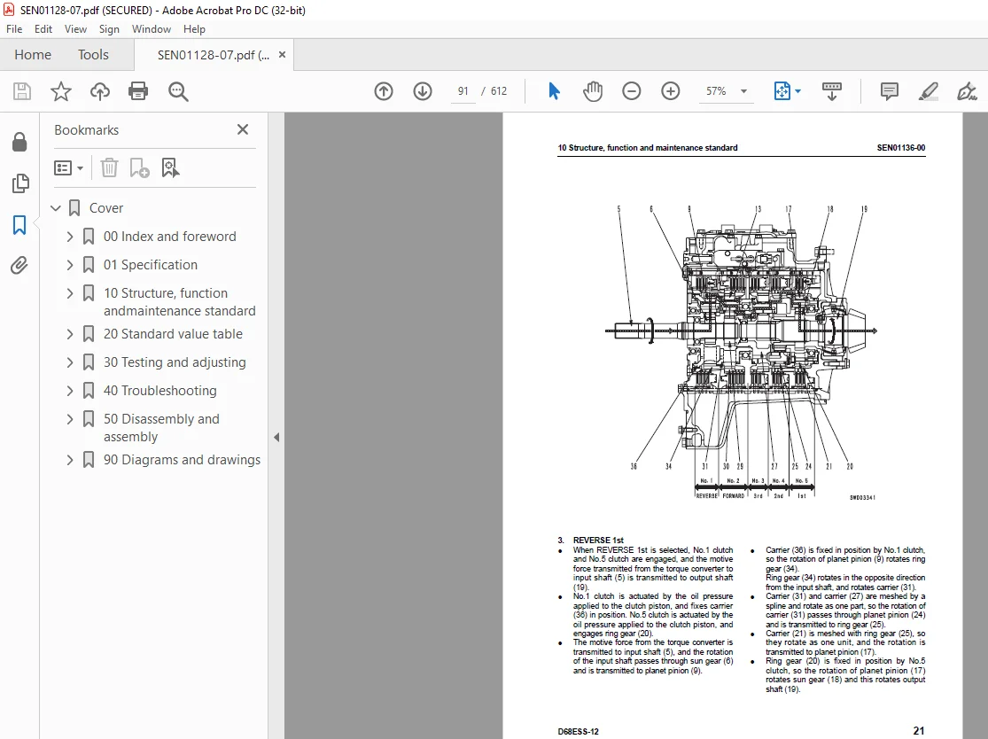
Power train skeleton 73
Power train unit 74
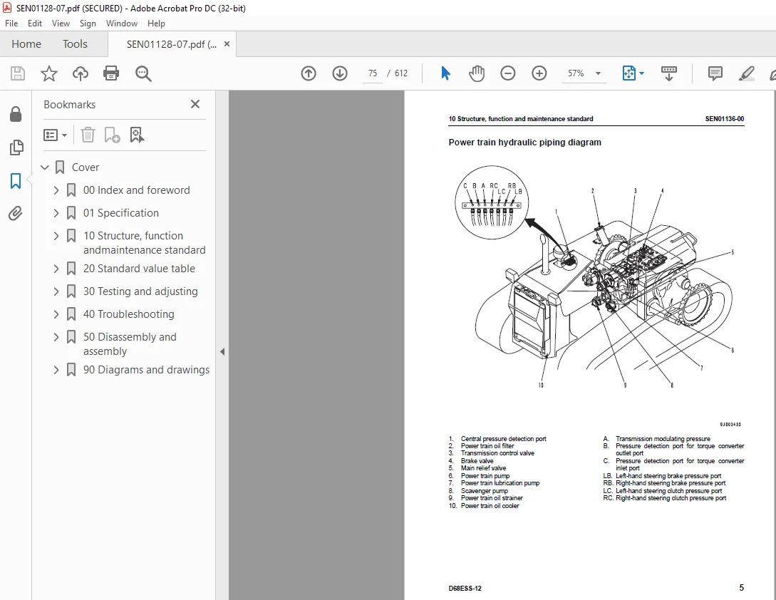
Power train hydraulic piping diagram 75
Damper, universal joint 76
Torque converter and PTO 79
Transmission control 84
Transmission 85
Transmission control valve 94
Main relief valve100
Lubrication relief valve103
Steering and brake control104
Power train, Part 2107
Power train, Part 2108
Bevel gear shaft, steering clutch and brake108
Brake valve118
Scavenging pump strainer123
Power train oil strainer124
Power train oil filter125
Final drive126
Undercarriage and frame133
Undercarriage and frame134
Main frame134
Suspension136
Track frame139
Recoil spring140
Idler142
Track roller143
Carrier roller144
Track shoe146
Hydraulic system, Part 1149
Hydraulic system, Part 1150
Work equipment hydraulic piping diagram150
PPC control piping diagram154
Work equipment control155
Hydraulic tank and filter158
Hydraulic pump160
Power train lubrication pump161
PPC valve (for steering)162
PPC charge valve167
Hydraulic system, Part 2171
Hydraulic system, Part 2172
1-spool valve 1
Main control valve172
CLSS178
Functions, operation of valve180
Suction valve188
3-spool valve 1
Main control valve190
CLSS197
Functions, operation of valve199
Suction valve208
Work equipment211
Work equipment212
Work equipment212
Cutting edge, end bit222
Work equipment cylinder224
Electrical system227
Electrical system228
Engine control228
Machine monitor system229
Sensors232
20 Standard value table237
Standard service value table237
Standard service value table238
Standard value table for engine238
Standard value table for chassis239
Standard value table for electrical system244
30 Testing and adjusting247
Testing and adjusting247
Testing and adjusting248
Tools for testing, adjusting, and troubleshooting248
Measuring blow-by pressure249
Measuring exhaust color250
Measuring engine oil pressure251
Measuring engine speed252
Testing fan belt tension253
Measuring speed at torque254
Adjusting fuel control linkage255
Adjusting steering/directional lever, gearshift lever, and parking brake lever257
Adjusting brake pedal linkage260
Adjusting work equipment lock lever261
Measuring power train hydraulic pressure262
Measuring and adjusting work equipment oil pressure265
Measuring leakage inside cylinder266
Bleeding air from hydraulic cylinder266
40 Troubleshooting269
General information on troubleshooting269
General information on troubleshooting270
Points to remember when troubleshooting270
How to proceed troubleshooting271
Connector types and mounting locations273
Connector pin arrangement diagram274
How to distinguish wire code276
Wiring table for connector pin numbers280
T-adapter box and T-adapter table313
How to follow the troubleshooting flow diagrams316
Troubleshooting of electrical system (E-mode)319
Troubleshooting of electrical system (E-mode)320
Table of failure modes and causes (Electrical system)320
Electrical circuit diagram for each system322
E-1 Starting motor is not cranked when starting switch is turned to ON330
E-2 Lamps do not light up336
Troubleshooting of hydraulic and mechanical system (H-mode)341
Troubleshooting of hydraulic and mechanical system (H-mode)344
Table of failure modes and causes (hydraulic, mechanical system)344
H-1 Brake does not work346
H-2 Machine does not turn (can travel in a straight line)347
H-3 Overruns when turning348
H-4 Can turn in only one direction (when steering lever is operated)348
H-5 Excessive time lag349
H-6 Machine can travel in only one direction (forward or reverse)349
H-7 Machine does not move (when engine is started and lever is shifted to 2nd or 3rd)350
H-8 Machine does not move in any speed range352
H-9 Power train oil temperature rises too high354
H-10 Drawbar pull is weak, travel speed is slow356
H-11 Abnormal noise is generated from around hydraulic pump358
H-12 Work equipment speed is slow or lacks power358
H-13 No work equipment moves359
H-14 Blade lift or tilt cylinder speed is slow or lacks power359
H-15 Blade angle cylinder speed is slow or lacks power360
H-16 Hydraulic drift of blade lift is excessive360
H-17 Hydraulic drift of blade tilt is excessive361
H-18 Hydraulic drift of blade angle is excessive361
Troubleshooting of machine monitor system (M-mode)363
Troubleshooting of machine monitor system (M-mode)364
Table of failure modes and causes (machine monitor system)364
Electrical circuit diagrams for each system366
M-1 Caution item lights up374
M-2 Gauge is abnormal378
M-3 Service meter does not move after engine is started386
M-4 Monitor panel lighting does not light up (front lamps are normal)387
50 Disassembly and assembly391
General information on disassembly and assembly391
General information on disassembly and assembly392
How to read this manual392
Coating materials list394
Special tool list397
Sketches of special tools401
Engine and cooling system405
Engine and cooling system406
Removal and installation of engine assembly406
Removal and installation of radiator and guard assembly408
Removal and installation of radiator assembly410
Removal and installation of hydraulic oil cooler assembly413
Removal and installation of fuel tank assembly414
Removal and installation of damper assembly415
Power train419
Power train421
Removal and installation of PTO, torque converter and transmission assembly421
Disconnection and connection of PTO, torque converter and transmission assembly425
Disassembly and assembly of PTO assembly427
Disassembly and assembly of torque converter assembly432
Disassembly and assembly of TORQFLOW transmission assembly436
Removal and installation of torque converter main relief valve assembly453
Disassembly and assembly of torque converter main relief valve assembly454
Removal and installation of transmission control valve assembly455
Disassembly and assembly of transmission control valve assembly456
Removal and installation of steering clutch and brake assembly458
Disassembly and assembly of steering clutch and brake assembly459
Removal and installation of bevel gear and bevel gear shaft (Clutch and brake model)466
Removal and installation of brake valve assembly472
Disassembly and assembly of brake valve assembly473
Removal and installation of scavenging pump assembly476
Removal and installation of power train and lubricating oil pump assembly477
Removal and installation of final drive assembly479
Disassembly and assembly of final drive assembly480
Undercarriage and frame493
Undercarriage and frame494
Removal and installation of track frame assembly494
Removal and installation of recoil spring assembly496
Disassembly and assembly of recoil spring assembly497
Removal and installation of idler assembly500
Disassembly and assembly of idler assembly501
Removal and installation of track roller assembly505
Disassembly and assembly of track roller assembly506
Removal and installation of carrier roller assembly509
Disassembly and assembly of carrier roller assembly510
Removal and installation of track shoe assembly512
Overall disassembly and assembly of track shoe assembly513
Field disassembly and assembly of one link529
Removal and installation of pivot shaft assembly536
Removal and installation of equalizer bar assembly538
Removal and installation of equalizer bar side bushing540
Removal installation of segment teeth540
Hydraulic system543
Hydraulic system544
Removal and installation of work equipment pump assembly544
Removal and installation of work equipment control valve assembly545
Disassembly and assembly of work equipment control valve assembly547
Removal and installation of steering PPC valve assembly551
Disassembly and assembly of steering PPC valve assembly552
Removal and installation of suction valve assembly555
Removal and installation of blade angle cylinder assembly556
Removal and installation of blade tilt cylinder assembly557
Removal and installation of blade lift cylinder assembly558
Disassembly and assembly of hydraulic cylinder assembly559
Work equipment565
Work equipment566
Removal and installation of work equipment assembly566
Disassembly and assembly of work equipment assembly572
Cab and its attachments577
Cab and its attachments578
Removal and installation of floor frame assembly578
Removal and installation of sweep guard582
Electrical system585
Electrical system586
Removal and installation of dashboard assembly586
Removal and installation of panel assembly587
90 Diagrams and drawings589
Hydraulic diagrams and drawings589
Hydraulic diagrams and drawings591
Power train hydraulic circuit diagram591
Work equipment hydraulic circuit diagram (1-spool valve (angle dozer))593
Work equipment hydraulic circuit diagram (3-spool valve (angle tilt dozer))595
Work equipment hydraulic circuit diagram (2-spool valve (trimming dozer))597
Electrical diagrams and drawings601
Electrical diagrams and drawings603
Forestry specification, general construction specification
Electrical circuit diagram (Serial No 1001 – 1002, J10001 – J10010)603
Electrical circuit diagram (Serial No 1003 and up, J10011 and up)605
Trimming dozer
Electrical circuit diagram (1/2)607
Electrical circuit diagram (2/2)609
IMAGES PREVIEW OF THE MANUAL:
S.M 25/12/24