Komatsu Cummins N855-C, NT855-C, NTA855-C, N-855 Series Diesel Engine Shop Manual – PDF DOWNLOAD
Original price was: $56.95.$24.95Current price is: $24.95.
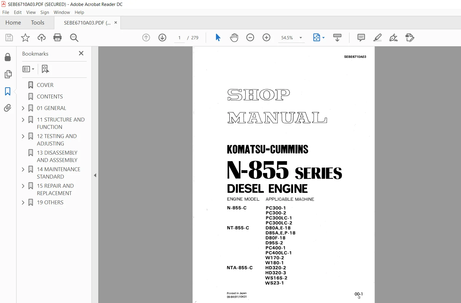
KomatsuCummins N855-C, NT855-C, NTA855-C, N-855 Series Diesel Engine Shop Manual
Book Code: SEBE6710A03
SERIAL NUMBER:
N-855-C P0300-1
PC300-2
PC300LC-1
PC300LC-2
NT-855-C 080A,E-1 8
085A.E.P-18
080F-1 8
0958-2
PC400-1
PC4OOLC-1
W1 70-2
W1 80-1
NTA-855-C H0320-2
H0320-3
WS168-2
W823-1
Description
Komatsu Cummins N855-C, NT855-C, NTA855-C, N-855 Series Diesel Engine Shop Manual
FILE DETAILS:
Komatsu Cummins N855-C, NT855-C, NTA855-C, N-855 Series Diesel Engine Shop Manual
Brands: Komatsu/Cummins
Equipment Type: Diesel Engine
Manuals Type: Shop Manual
Machine Model: N855-C, NT855-C, NTA855-C, N855 Series Diesel Engine
Serial Number: 26100001 and up
Book Code: SEBE6710A03
Language: English
Pages: 279
KOMATSU CUMMINS N855-C, NT855-C, NTA855-C, N-855 SERIES DIESEL ENGINE SHOP MANUAL – PDF DOWNLOAD:
IMAGES PREVIEW OF THE MANUAL:
DESCRIPTION:
Komatsu Cummins N855-C, NT855-C, NTA855-C, N-855 Series Diesel Engine Shop Manual
FOREWORD:
GENERAL:
- This shop manual has been prepared as an aid to improve the quality of repairs by giving the servicemen an accurate understanding of the product and by showing him the correct way to perform repairs and make judgements. Make sure you understand the contents of this manual and use it to full effect at every opportunity.
- This shop manual mainly contains the necessary technical information for operations performed in a service workshop. For ease of understanding, the manual is divided into the following chapters; these chapters are further divided into the each main group of components.
STRUCTURE AND FUNCTION:
This section explains the structure and function of each component. It serves not only to give an understanding of the structure, but also serves as reference material for troubleshooting.
TESTING AND ADJUSTING:
This section explains checks to be made before and after performing repairs, as well as adjustments to be made at completion of the checks and repairs. Troubleshooting charts correlating “Problems” to “Causes” are also included in thissection.
DISASSEMBLY AND ASSEMBLY:
This section explains the order to be followed when removing, installing, disassembling or assembling each component, as well as precautions to be taken for these operations.
MAINTENANCE STANDARD :
This section gives the judgement standards when inspecting disassembled parts.
TABLE OF CONTENTS:
Komatsu Cummins N855-C, NT855-C, NTA855-C, N-855 Series Diesel Engine Shop Manual
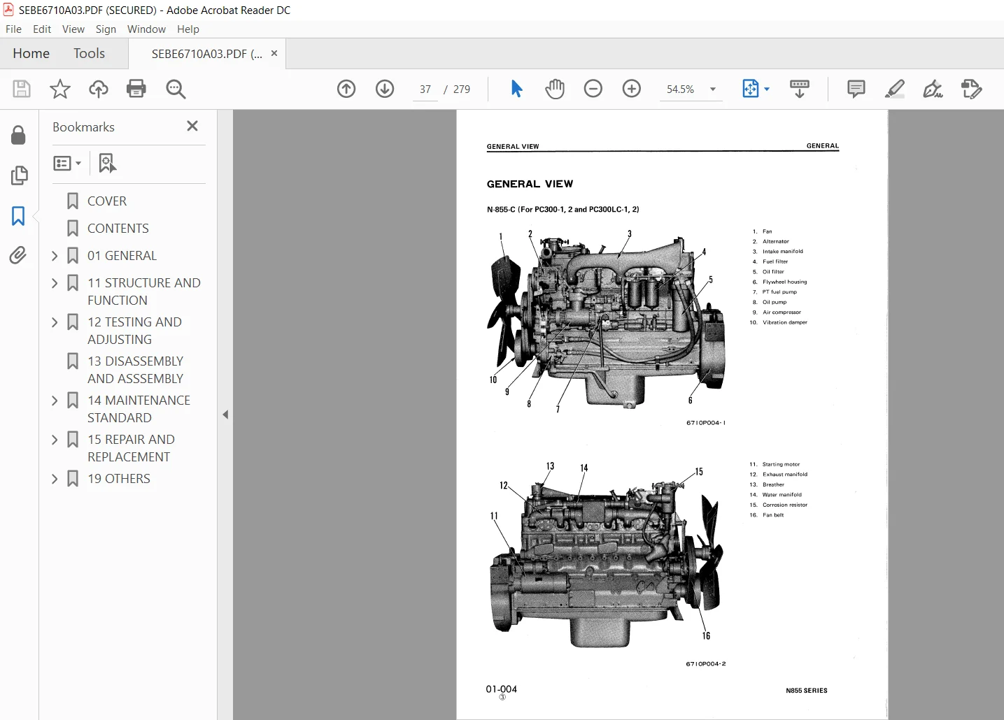
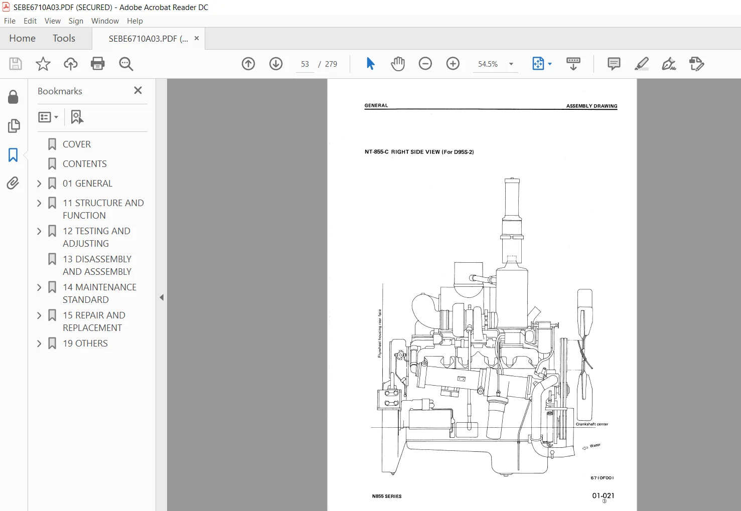
COVER..............................................................  1
CONTENTS...........................................................  2
01 GENERAL......................................................... 35
	CONTENTS....................................................... 36
		GENERAL VIEW............................................... 37
		SPECIFICATIONS............................................. 40
		ASSEMBLY DRAWING........................................... 44
		PERFORMANCE CURVE.......................................... 64
		WEIGHT TABLE............................................... 73
11 STRUCTURE AND FUNCTION.......................................... 74
	CONTENTS....................................................... 75
		GENERAL STRUCTURE.......................................... 76
		INTAKE AND EXHAUST SYSTEM.................................. 78
			TURBOCHARGER........................................... 86
			AFTER-COOLER........................................... 88
		ENGINE BODY................................................ 89
			CYLINDER HEAD.......................................... 89
			VALVE SYSTEM........................................... 90
			CYLINDER BLOCK......................................... 92
			MAIN CIRCULATION SYSTEM................................ 94
			TIMING GEAR............................................ 95
			CAMSHAFT, CAM FOLLOWER AND PUSH ROD.................... 96
			INJECTION TIMING, VALVE TIMING......................... 97
			FLYWHEEL AND FLYWHEEL HOUSING.......................... 98
		LUBRICATION SYSTEM.........................................105
			LUBRICATION SYSTEM CHART...............................105
			OIL PUMP...............................................107
			OIL FILTER AND OIL COOLER..............................110
			FULL-FLOW FILTER.......................................113
			BY-PASS FILTER.........................................114
			OIL COOLER.............................................115
		FUEL SYSTEM................................................116
			FUEL SYSTEM CHART......................................116
			PT FUEL PUMP...........................................119
			PT FUEL PUMP DRIVE.....................................129
			INJECTOR...............................................131
			FUEL FILTER............................................132
			WATER SEPARATOR........................................134
			ANEROID CONTROL VALVE..................................135
		COOLING SYSTEM.............................................136
			COOLING SYSTEM CHART...................................136
			WATER PUMP.............................................138
			FAN DRIVE..............................................141
			TENSION PULLEY.........................................145
			THERMOSTAT.............................................147
			CORROSION RESISTOR.....................................148
		ACCESSORY..................................................149
			AIR COMPRESSOR.........................................149
		ELECTRICAL SYSTEM..........................................150
			ALTERNATOR.............................................150
			STARTING MOTOR.........................................153
			ELECTRICAL INTAKE AIR HEATER...........................155
12 TESTING AND ADJUSTING...........................................157
	CONTENTS.......................................................158
		TESTING AND ADJUSTING INJECTOR AND VALVE CLEARANCE.........159
		MEASURING COMPRESSION PRESSURE.............................162
		MEASURING BLOW-BY PRESSURE.................................164
		MEASURING OIL CONSUMPTION..................................166
		MEASURING FUEL PRESSURE....................................168
		PT PUMP CALIBRATION DATA...................................169
		PT FUEL PUMP PARTS SPECIFICATION...........................181
		INJECTOR SPECIFICATION.....................................191
		RUN-IN STANDARD............................................192
		PERFORMANCE TEST CRITERIA..................................194
		TESTING AND ADJUSTING TOOL LIST............................198
		TESTING AND ADJUSTING DATA.................................199
		TROUBLESHOOTING............................................204
13 DISASSEMBLY AND ASSSEMBLY.......................................226
14 MAINTENANCE STANDARD............................................227
	CONTENTS.......................................................228
		INTAKE AND EXHAUST SYSTEM..................................229
			TURBOCHARGER...........................................229
		ENGINE BODY................................................231
			CYLINDER HEAD..........................................231
			VALVE, VALVE GUIDE.....................................232
			CROSSHEAD AND CROSSHEAD GUIDE..........................233
			ROCKER LEVER, SHAFT....................................234
			CYLINDER BLOCK.........................................235
			CRANKSHAFT AND VIBRATION DAMPER........................237
			CYLINDER LINER.........................................239
			CAMSHAFT...............................................240
			CAM FOLLOWER AND PUSH ROD..............................241
			GEAR AND GEAR COVER....................................242
			CONNECTING ROD.........................................243
			PISTON, PISTON RING, PISTION PIN.......................245
			FLYWHEEL, FLYWHEEL HOUSING, REAR COVER.................246
		LUBRICATION SYSTEM.........................................247
			OIL PUMP...............................................247
		COOLING SYSTEM.............................................249
			WATER PUMP AND IDLER PULLEY............................249
15 REPAIR AND REPLACEMENT..........................................250
	CONTENTS.......................................................251
		CYLINDER HEAD..............................................252
			GRINDING AND CORRECTING CYLINDER HEAD MOUNTING FACE....252
			REPLACING VALVE SEAT INSERTS...........................253
			GRINDING AND CORRECTING VALVE SEATS SURFACE............256
			REPLACING INJECTOR SLEEVES.............................257
			REPLACING VALVE GUIDES.................................260
			REPLACING CROSSHEAD GUIDES.............................261
			GRINDING AND CORRECTING VALVES.........................261
			REPLACING ROCKER LEVER BUSHINGS........................261
		CYLINDER BLOCK.............................................262
			GRINDING AND CORRECTING TOP FACE OF CYLINDER BLOCK.....262
			CORRECTING CYLINDER LINER COUNTERBORE..................263
			REPLACING MAIN BEARING CAPS............................264
			GRINDING AND CORRECTING CRANKSHAFT.....................268
			CORRECTING SLEEVES AT CRANKSHAFT REAR SEAL.............272
			REPLACING CAMSHAFT BUSHING.............................273
			REPLACING CONNECTING ROD BUSHING.......................274
			REPLACING CAM FOLLOWER LEVER BUSHING...................275
			REPLACING CRANKSHAFT GEAR..............................276
			REPLACING CAMSHAFT GEAR................................276
			REPLACING FLYWHEEL RING GEAR...........................276
19 OTHERS..........................................................277
	CONTENTS.......................................................278
		STANDARD TIGHTENING TORQUE.................................279
PLEASE NOTE:
- This is the SAME MANUAL used by the dealerships to diagnose your vehicle
- No waiting for couriers / posts as this is a PDF manual and you can download it within 2 minutes time once you make the payment.
- Your payment is all safe and the delivery of the manual is INSTANT – You will be taken to the DOWNLOAD PAGE.
- So have no hesitations whatsoever and write to us about any queries you may have : heydownloadss @gmail.com


Leroy Kyng –