Description
Komatsu D155A-6 Bulldozer Shop Manual SEN02854-24 Serial 85001 and Up
This Komatsu D155A-6 Bulldozer Shop Manual SEN02854-24 Serial 85001 and Up is the chassis workshop volume written for the D155A-6 crawler dozer from serial number 85001 onward. It gathers specification data, component structure and maintenance standards, service-value tables, testing and adjusting procedures, failure-code and symptom troubleshooting, removal and assembly sequences, air-conditioner service, and the hydraulic and electrical diagrams used on this machine. The binder form number printed on the cover is SEN02854-24. Individual section form numbers appear throughout the book, including SEN02855-24 through SEN02875-01 and later revisions such as SEN04441-03 for the air conditioner.
Komatsu shop manuals for this family are split into a chassis volume and a separate engine volume. This file is the chassis volume. For internal overhaul of the engine unit itself, the engine volume for the mounted engine model is required. Chassis-side engine work that is in this book includes cooling-system service, fuel-system tests on the machine, injector and supply-pump removal, cylinder-head removal, front and rear seal replacement, and engine-assembly R&I.
File Details
- Manual type: Shop manual (chassis volume)
- Brand / model: Komatsu D155A-6 bulldozer
- Serial range: 85001 and up
- Document / binder number: SEN02854-24
- Language: English
- Page count: 1566
- File format: PDF
- Copyright notice in the index section: © 2022 Komatsu, printed in Japan 12-22 (01)
Machine and Powerplant Coverage
The specification section identifies one machine model, D155A-6, serial numbers 85001 and up. The mounted engine is named SAA6D140E-5: a 4-cycle, water-cooled, in-line, vertical, direct-injection diesel with turbocharger and aftercooler. Cylinder layout is 6 − 140 × 165 mm, piston displacement 15.24 ℓ (15,240 cc). Flywheel horsepower is given as 239 kW {320 HP} at 1,900 rpm, maximum torque 1,834 Nm {187 kgm} at 1,300 rpm, no-load maximum speed 2,100 rpm, and no-load minimum speed 740 rpm. Starting motor is 24 V, 11 kW; alternator 24 V, 50 A; batteries 12 V, 136 Ah × 2.
Published machine weights include a bare tractor of 31,200 kg and 41,700 kg with semi U-tilt dozer, variable giant ripper, ROPS cab, air conditioner, 560 mm HD shoe, and side cover (42,080 kg with multi ripper). Track gauge is 2,140 mm, length of track on ground 3,150 mm, standard shoe width 560 mm, and minimum ground clearance to the undercover 500 mm. Forward transmission speeds are listed as 3.9 / 5.7 / 7.5 / 11.4 km/h and reverse as 4.7 / 6.8 / 9.2 / 13.7 km/h. Power-train architecture is a 3-element, 1-stage, 1-phase torque converter; planetary hydraulically actuated transmission with three forward and three reverse speeds; wet multi-disc steering clutches and brakes; and a final drive of one spur-gear stage plus one planetary stage.
Work-equipment hydraulics use a variable swash-plate pump HPV112 with maximum delivery pressure 27.5 MPa {280 kg/cm²} and theoretical delivery 216 ℓ/min at 2,250 rpm. Blade options documented are hydraulic sigma-tilt, semi U-tilt, and U-tilt dozers (SAE capacities 9.4 m³ on sigma and semi-U, 11.9 m³ on full U). Rear attachments include the variable multi-shank ripper and variable giant ripper. Fluid capacities in the specification tables are engine oil pan 45 ℓ specified / 37 ℓ refill, power-train case 105 ℓ / 70 ℓ, damper case 1.5 ℓ, final drive 31 ℓ each side, hydraulic system with blade and without ripper 240 ℓ specified / 85 ℓ refill, fuel tank 625 ℓ, and cooling system 82 ℓ.
Complete PDF Bookmark Tree
Complete Bookmarks
The complete bookmarks in the “Komatsu D155A-6 Bulldozer Shop Manual SEN02854-24 Serial 85001 and Up” are as follows:
+Coverp. 1
+00 Index and forewordp. 3
+Indexp. 3
Composition of shop manualp. 4
Table of contentsp. 6
+Foreword and general informationp. 17
Safety noticep. 18
How to read the shop manualp. 23
Explanation of terms for maintenance standardp. 25
Handling of electric equipment and hydraulic componentp. 27
Handling of connectors newly used for enginesp. 36
How to read electric wire codep. 39
Precautions when carrying out operationp. 42
Method of disassembling and connecting push-pull type couplerp. 45
Standard tightening torque tablep. 48
Conversion tablep. 52
+01 Specificationp. 59
+Specification and technical datap. 59
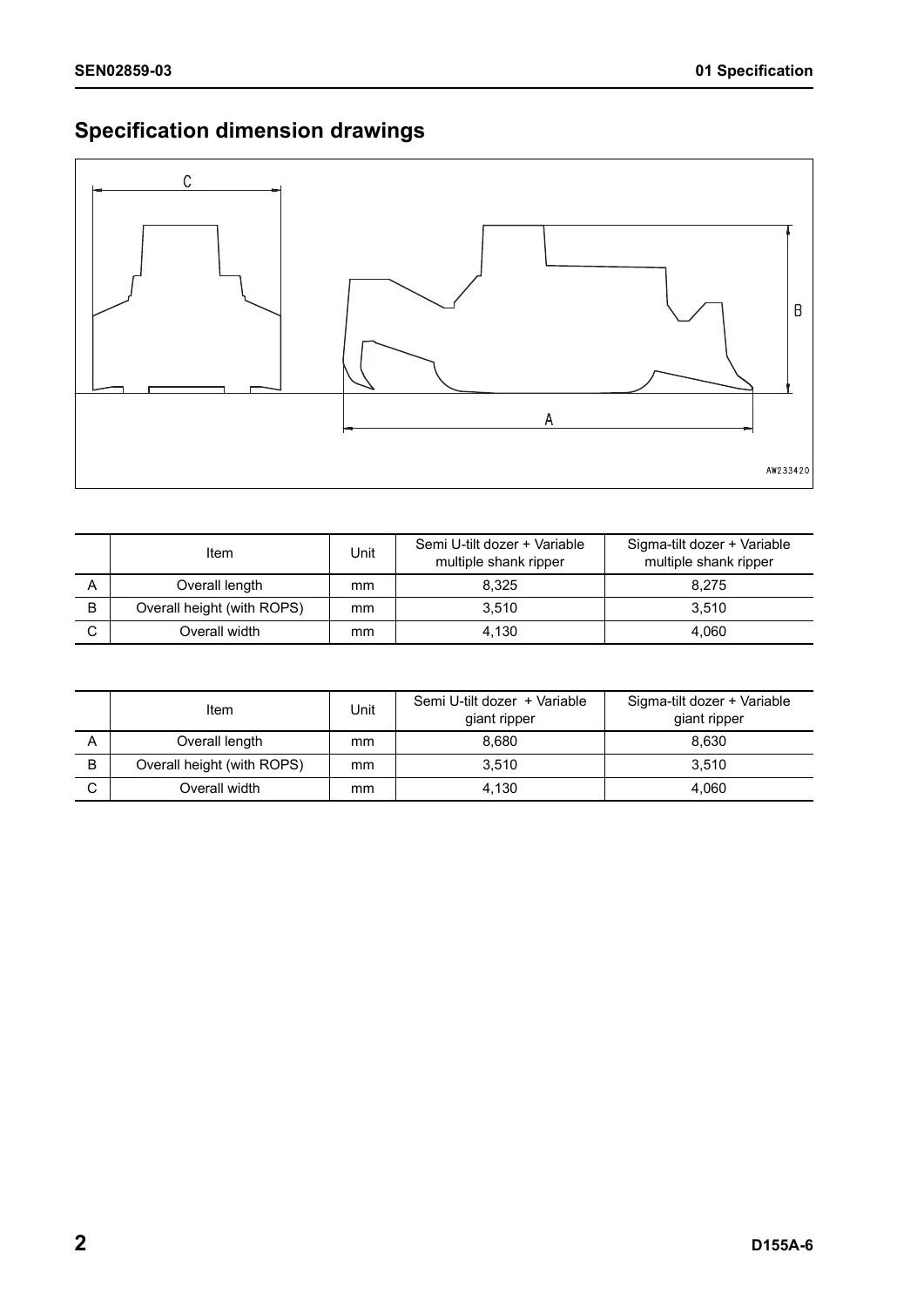
Specification dimension drawingsp. 60
Specificationsp. 61
Weight tablep. 67
Table of fuel, coolant and lubricantsp. 70
+10 Structure, function and maintenance standardp. 73
+Engine and cooling systemp. 73
Radiator, oil coolerp. 74
Engine mountp. 81
Cooling fan pumpp. 82
Cooling fan motorp. 90
+Power train, Part 1p. 97
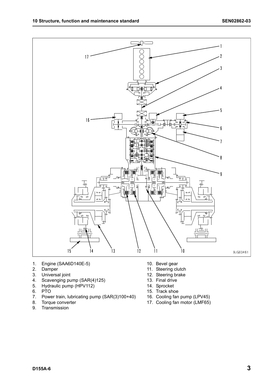
Power train skeletonp. 98
Overall drawing of power train unitp. 100
Power train hydraulic piping drawingp. 102
Damper, universal jointp. 104
Torque converter, PTOp. 106
Transmissionp. 114
Transmission ECMVp. 130
Main relief valve and torque converter relief valvep. 136
Lubricating oil relief valvep. 138
Scavenging pumpp. 140
Power train and steering lubrication pumpp. 142
+Power train, Part 2p. 145
Work equipment pumpp. 146
Work equipment cooler bypass valvep. 159
Steering, brake controlp. 160
Steering unitp. 162
Steering control valvep. 176
Steering clutch ECMV, steering brake ECMVp. 178
Parking brake solenoid valvep. 184
Sudden stop prevention valvep. 186
Final drivep. 189
Sprocketp. 194
+Undercarriage and framep. 197
Track framep. 198
Recoil springp. 200
Idlerp. 202
Track rollerp. 204
Carrier rollerp. 206
Track shoep. 208
Main framep. 214
Suspensionp. 216
+Hydraulic systemp. 219
Work equipment hydraulic piping diagramp. 220
Work equipment control piping diagramp. 224
Work equipment controlp. 226
Hydraulic tank and filterp. 228
Accumulatorp. 231
PPC valvep. 232
Work equipment lock valvep. 244
Control valvep. 246
Work equipment cylinderp. 268
Piston valvep. 270
Quick drop valvep. 272
Self pressure reducing valvep. 273
+Work equipmentp. 281
Cylinder stayp. 282
Bladep. 284
Ripperp. 288
Cutting edge, end bitp. 286
+Cab and its attachmentsp. 295
Cab mount + ROPS pinp. 296
ROPS cabp. 297
ROPS floorp. 298
Air conditionerp. 299
+Electrical systemp. 301
Engine controlp. 302
Engine control systemp. 303
Deceleration potentiometerp. 304
Monitor systemp. 306
Sensorsp. 325
Palm command control systemp. 328
KOMTRAX systemp. 331
+20 Standard value tablep. 335
+Standard service value tablep. 335
Standard value table for enginep. 336
Standard value table for machinep. 337
+30 Testing and adjustingp. 347
+Testing and adjusting, Part 1p. 347
Tools for testing, adjusting, and troubleshootingp. 349
Sketches of special toolsp. 354
Measuring engine speedp. 357
Measuring intake air pressure (boost pressure)p. 359
Measuring exhaust temperaturep. 361
Measuring exhaust gas colorp. 363
Adjusting valve clearancep. 364
Measuring compression pressurep. 365
Measuring blow-by pressurep. 367
Measuring engine oil pressurep. 368
Handling fuel system partsp. 369
Releasing residual pressure from fuel systemp. 369
Measuring fuel pressurep. 370
Measuring fuel return rate and fuel leakagep. 371
Bleeding air from fuel circuitp. 375
Measuring fuel circuit for leakagep. 377
Testing and adjusting alternator belt tensionp. 378
Testing and adjusting air conditioner compressor belt tensionp. 379
Measuring fan speedp. 380
Measuring fan circuit oil pressurep. 382
Bleeding air from fan pumpp. 383
Bleeding air from work equipment pumpp. 384
Adjusting fuel control dial and decelerator pedalp. 385
+Testing and adjusting, Part 2p. 389
Measuring power train oil pressurep. 391
Adjusting transmission output shaft speed sensorp. 399
Simple test procedure for brake performancep. 400
Adjusting brake pedalp. 401
Adjusting parking brake leverp. 403
Emergency escape method when power train has troublep. 405
Adjusting idler clearancep. 408
Testing and adjusting track shoe tensionp. 410
Measuring and adjusting work equipment oil pressurep. 411
Measuring control circuit basic pressurep. 414
Measuring work equipment lock solenoid valve output pressure (PPC valve basic pressure)p. 415
Measuring PPC valve output pressurep. 416
Adjusting work equipment PPC valve playp. 418
Measuring ripper pin puller solenoid valve output pressurep. 420
Testing parts which cause hydraulic drift of blade and ripperp. 421
Measuring internal leakage of work equipment cylinderp. 422
Releasing residual pressure from work equipment cylinderp. 423
Bleeding air from work equipment cylinderp. 423
Adjusting work equipment lock leverp. 424
Adjusting bladep. 425
Testing and adjusting play of blade electric leverp. 427
Adjusting operator's cabp. 435
+Testing and adjusting, Part 3p. 441
Special functions of machine monitor (EMMS)p. 442
+Testing and adjusting, Part 4p. 503
Handling of power supply circuit of engine controllerp. 504
Preparation work for troubleshooting of electrical systemp. 505
Pm Clinicp. 507
+40 Troubleshootingp. 519
+Failure code table and fuse locationsp. 519
Failure codes tablep. 520
Fuse locationsp. 526
+General information on troubleshootingp. 531
Points to remember when troubleshootingp. 532
Sequence of events in troubleshootingp. 533
Check before troubleshootingp. 534
Classification and procedures for troubleshootingp. 535
Information in troubleshooting tablep. 538
Connection table for connector pin numbersp. 540
T- branch box and T- branch adapter tablep. 576
+Troubleshooting by failure and error codes, Part 1p. 581
Failure code [1500L0]p. 583
Failure code [15SAL1]p. 584
Failure code [15SALH]p. 586
Failure code [15SBL1]p. 588
Failure code [15SBLH]p. 590
Failure code [15SEL1]p. 592
Failure code [15SELH]p. 594
Failure code [15SFL1]p. 596
Failure code [15SFLH]p. 598
Failure code [15SGL1]p. 600
Failure code [15SGLH]p. 602
Failure code [2201L1]p. 604
Failure code [2201LH]p. 606
Failure code [2202L1]p. 608
Failure code [2202LH]p. 610
Failure code [2300KM]p. 612
Failure code [2301L1]p. 613
Failure code [2301LH]p. 615
Failure code [2302L1]p. 617
Failure code [2302LH]p. 619
Failure code [7RFAKA]p. 621
Failure code [AA10NX]p. 623
Failure code [AB00MA]p. 625
Failure code [B@BAZG]p. 627
Failure code [B@BCNS]p. 628
Failure code [B@BCZK]p. 629
Failure code [B@CENS]p. 630
Failure code [B@HANS]p. 631
Failure code [CA111]p. 632
Failure code [CA115]p. 634
Failure code [CA122]p. 636
Failure code [CA123]p. 639
Failure code [CA131]p. 640
Failure code [CA132]p. 642
Failure code [CA135]p. 643
Failure code [CA141]p. 646
Failure code [CA144]p. 647
Failure code [CA145]p. 649
Failure code [CA153]p. 650
Failure code [CA154]p. 652
Failure code [CA187]p. 652
Failure code [CA221]p. 653
Failure code [CA222]p. 656
Failure code [CA227]p. 657
+Troubleshooting by failure and error codes, Part 2p. 661
Failure code [CA234]p. 663
Failure code [CA238]p. 664
Failure code [CA263]p. 666
Failure code [CA265]p. 668
Failure code [CA271]p. 669
Failure code [CA272]p. 671
Failure code [CA273]p. 673
Failure code [CA274]p. 675
Failure code [CA322]p. 677
Failure code [CA323]p. 679
Failure code [CA324]p. 681
Failure code [CA325]p. 683
Failure code [CA331]p. 685
Failure code [CA332]p. 687
Failure code [CA342]p. 689
Failure code [CA351]p. 690
Failure code [CA352]p. 692
Failure code [CA386]p. 693
Failure code [CA441]p. 695
Failure code [CA442]p. 695
Failure code [CA449]p. 696
Failure code [CA451]p. 697
Failure code [CA452]p. 700
Failure code [CA553]p. 701
Failure code [CA554]p. 703
Failure code [CA559]p. 704
Failure code [CA689]p. 710
Failure code [CA731]p. 712
Failure code [CA757]p. 713
Failure code [CA778]p. 714
Failure code [CA1633]p. 717
Failure code [CA2185]p. 719
Failure code [CA2186]p. 721
Failure code [CA2249]p. 721
Failure code [CA2555]p. 722
Failure code [CA2556]p. 723
Failure code [D110KA]p. 725
Failure code [D110KB]p. 727
Failure code [D130KA]p. 729
Failure code [D130KB]p. 732
Failure code [D161KA]p. 734
Failure code [D161KB]p. 736
Failure code [D190KA]p. 738
Failure code [D190KB]p. 740
+Troubleshooting by failure and error codes, Part 3p. 743
Failure code [D5ZKKX]p. 745
Failure code [DAFRKR]p. 748
Failure code [DAFRMC]p. 750
Failure code [DB2RKR]p. 757
Failure code [DB90KR]p. 760
Failure code [DBE0KK]p. 762
Failure code [DBE0KT]p. 765
Failure code [DBE6KK]p. 766
Failure code [DBE7KK]p. 768
Failure code [DBE9KQ]p. 771
Failure code [DD12KA]p. 773
Failure code [DD12KB]p. 775
Failure code [DD13KA]p. 777
Failure code [DD13KB]p. 779
Failure code [DD14KA]p. 781
Failure code [DD14KB]p. 783
Failure code [DDDDKA]p. 785
Failure code [DDDDKB]p. 787
Failure code [DDDDKX]p. 789
Failure code [DGT1KA]p. 790
Failure code [DGT1KX]p. 792
Failure code [DH21KA]p. 794
Failure code [DH21KB]p. 796
Failure code [DK10KX]p. 798
Failure code [DK30KA]p. 801
Failure code [DK30KB]p. 803
Failure code [DK30KX]p. 805
Failure code [DK30KZ]p. 805
Failure code [DK30L8]p. 806
Failure code [DK31KA]p. 807
Failure code [DK31KB]p. 809
Failure code [DK40KA]p. 811
Failure code [DK40KB]p. 813
Failure code [DK55KX]p. 815
Failure code [DK55KZ]p. 815
Failure code [DK55L8]p. 816
Failure code [DK56KA]p. 817
Failure code [DK56KB]p. 819
+Troubleshooting by failure and error codes, Part 4p. 823
Failure code [DK57KA]p. 826
Failure code [DK57KB]p. 828
Failure code [DKH1KA]p. 830
Failure code [DKH1KB]p. 832
Failure code [DLT3KA]p. 834
Failure code [DLT3KB]p. 836
Failure code [DW7BKA]p. 838
Failure code [DW7BKB]p. 840
Failure code [DWN3KA]p. 842
Failure code [DWN3KB]p. 844
Failure code [DWN3KY]p. 846
Failure code [DWN5KA]p. 848
Failure code [DWN5KB]p. 850
Failure code [DXH4KA]p. 852
Failure code [DXH4KB]p. 854
Failure code [DXH4KY]p. 856
Failure code [DXH5KA]p. 858
Failure code [DXH5KB]p. 860
Failure code [DXH5KY]p. 862
Failure code [DXH6KA]p. 864
Failure code [DXH6KB]p. 866
Failure code [DXH6KY]p. 868
Failure code [DXH7KA]p. 870
Failure code [DXH7KB]p. 872
Failure code [DXH7KY]p. 874
Failure code [DXH8KA]p. 876
Failure code [DXH8KB]p. 878
Failure code [DXH8KY]p. 880
Failure code [DXH9KA]p. 882
Failure code [DXH9KB]p. 884
Failure code [DXH9KY]p. 886
Failure code [DXHAKA]p. 888
Failure code [DXHAKB]p. 890
Failure code [DXHAKY]p. 892
Failure code [DXHBKA]p. 894
Failure code [DXHBKB]p. 896
Failure code [DXHBKY]p. 898
Failure code [DXHCKA]p. 900
Failure code [DXHCKB]p. 902
Failure code [DXHCKY]p. 904
Failure code [DXJ4KA]p. 906
Failure code [DXJ4KB]p. 908
+Troubleshooting of electrical system (E-mode)p. 911
Before carrying out troubleshooting for electrical systemp. 913
Information in troubleshooting tablep. 917
E-1 When starting switch turned ON, machine monitor displays nothingp. 918
E-2 When starting switch turned ON (before starting engine), basic check item lights up 1p. 920
E-3 Engine does not start (Engine does not turn)p. 922
E-4 Preheater does not operatep. 925
E-5 Precaution item lights up while engine is runningp. 928
E-6 Emergency stop item lights up while engine is runningp. 930
E-7 Engine coolant temperature gauge does not indicate normallyp. 932
E-8 Fuel level gauge does not indicate normallyp. 933
E-9 Power train oil temperature gauge (multi-gauge) does not indicate normallyp. 935
E-10 Hydraulic temperature gauge (multi-gauge) does not indicate normallyp. 936
E-11 Contents of display by machine monitor are different from applicable machinep. 938
E-12 Machine monitor does not display some itemsp. 938
E-13 Function switch does not workp. 938
E-14 Operation mode does not changep. 939
E-15 Gearshift mode does not changep. 939
E-16 Customize function does not operate normallyp. 940
E-17 Customize memory function does not normallyp. 940
E-18 Alarm buzzer cannot be stoppedp. 941
E-19 Air conditioner does not operate normally (including air conditioner fault history)p. 942
E-20 When starting switch is turned OFF, service meter is not displayedp. 956
E-21 Machine monitor cannot be set in service modep. 956
E-22 Ripper pin puller cylinder does not operatep. 958
E-23 Backup alarm does not sound or does not stopp. 960
E-24 Headlamp, rear lamp, and ripper point lamp do not light upp. 962
E-25 Windshield wiper and window washer do not operatep. 967
E-26 KOMTRAX terminal does not operate normallyp. 983
E-27 Fan does not reversep. 984
E-28 Gear cannot be shiftedp. 986
E-29 Electric priming pump does not operate or does not stop automaticallyp. 988
+Troubleshooting of hydraulic and mechanical system (H-mode)p. 991
Information in troubleshooting tablep. 993
H-1 Power is low (Drawbar pull is low)p. 994
H-2 Machine does not travel (at 2nd or 3rd gear speed)p. 995
H-3 Machine does not start at any gear speedp. 996
H-4 Machine can travel only forward or in reversep. 997
H-5 When gear speed or travel direction is changed, time lag is largep. 998
H-6 Steering is not possiblep. 999
H-7 Steering is possible only on one sidep. 1000
H-8 Steering overrun occursp. 1001
H-9 Brake does not workp. 1002
H-10 Power train oil is overheatedp. 1003
H-11 Speed of all work equipment is lowp. 1004
H-12 No work equipment movesp. 1005
H-13 Blade lift speed or power is lowp. 1006
H-14 Blade tilt speed or power is lowp. 1007
H-15 Ripper lift speed or power is lowp. 1008
H-16 Ripper tilt speed or power is lowp. 1009
H-17 Hydraulic drift of blade lift is largep. 1009
H-18 Hydraulic drift of blade tilt is largep. 1010
H-19 Hydraulic drift of ripper lift is largep. 1010
H-20 Ripper pin puller cylinder does not operatep. 1011
H-21 Abnormal sound comes out from around work equipment pumpp. 1012
H-22 Fan speed is abnormal (Sound and/or vibration are abnormally large or engine over heats)p. 1013
+Troubleshooting of engine (S-mode)p. 1015
Method of using troubleshooting chartp. 1017
S-1 Starting performance of engine is poorp. 1020
S-2 Engine does not startp. 1021
S-3 Engine does not pick up smoothlyp. 1024
S-4 Engine stops during operationp. 1025
S-5 Engine does not rotate smoothlyp. 1026
S-6 Engine lack output (or lacks power)p. 1027
S-7 Exhaust gas is black (incomplete combustion)p. 1028
S-8 Oil consumption is excessive (or exhaust gas is blue)p. 1029
S-9 Oil becomes dirty quicklyp. 1030
S-10 Fuel consumption is excessivep. 1031
S-11 Oil is in coolant (or coolant spurts back or coolant level goes down)p. 1032
S-12 Oil pressure dropsp. 1033
S-13 Oil level rises (Entry of coolant or fuel)p. 1034
S-14 Coolant temperature becomes too high (Overheating)p. 1035
S-15 Abnormal noise is madep. 1036
S-16 Vibration is excessivep. 1037
S-17 Air cannot be bled from fuel circuitp. 1038
+50 Disassembly and assemblyp. 1041
+General information on disassembly and assemblyp. 1041
How to read this manualp. 1042
Coating materials listp. 1044
Special tool listp. 1047
Sketches of special toolsp. 1055
+Engine and cooling systemp. 1067
Removal and installation of fuel supply pump assemblyp. 1068
Removal and installation of fuel injector assemblyp. 1073
Removal and installation of cylinder head assemblyp. 1079
Removal and installation of radiator assemblyp. 1090
Removal and installation of aftercooler assemblyp. 1093
Removal and installation of engine assemblyp. 1096
Removal and installation of engine hood assemblyp. 1101
Removal and installation of engine front sealp. 1103
Removal and installation of engine rear sealp. 1107
Removal and installation of fuel tank assemblyp. 1112
Removal and installation of fan drive assemblyp. 1114
Removal and installation of fan motor assemblyp. 1115
+Power train, Part 1p. 1117
Removal and installation of damper assemblyp. 1118
Disassembly and assembly of damper assemblyp. 1121
Removal and installation of power train unit assemblyp. 1127
Disconnection and connection of power train unit assemblyp. 1132
+Power train, Part 2p. 1139
Disassembly and assembly of PTO assemblyp. 1140
Disassembly and assembly of torque converter assemblyp. 1147
Disassembly and assembly of transmission assemblyp. 1152
Disassembly and assembly of steering case assemblyp. 1169
+Power train, Part 3p. 1185
Removal and installation of final drive assemblyp. 1186
Disassembly and assembly of final drive assemblyp. 1188
+Undercarriage and framep. 1203
Removal and installation of track frame assemblyp. 1205
Removal and installation of idler assemblyp. 1208
Disassembly and assembly of idler assemblyp. 1209
Removal and installation of recoil spring assemblyp. 1213
Disassembly and assembly of recoil spring assemblyp. 1214
Removal and installation of track roller assemblyp. 1219
Disassembly and assembly of track roller assemblyp. 1220
Removal and installation of 1st bogie assemblyp. 1222
Removal and installation of 2nd, 3rd, and 4th bogie assembliesp. 1231
Disassembly and assembly of bogie assemblyp. 1239
Removal and installation of carrier roller assemblyp. 1242
Disassembly and assembly of carrier roller assemblyp. 1243
Removal and installation of pivot shaft assemblyp. 1247
Spreading and installation of track shoe assemblyp. 1249
General disassembly and assembly of track shoep. 1252
Disassembly and assembly of 1 link in fieldp. 1266
Disassembly and assembly of master linkp. 1270
Removal and installation of equalizer bar assemblyp. 1273
Disassembly and assembly of equalizer bar assemblyp. 1275
Removal and installation of segment teethp. 1277
+Hydraulic systemp. 1279
Removal and installation of hydraulic tank assemblyp. 1280
Removal and installation of hydraulic pump assemblyp. 1282
Disassembly and assembly of hydraulic cylinder assemblyp. 1285
+Work equipmentp. 1297
Removal and installation of blade assemblyp. 1298
Removal and installation of blade lift cylinder assemblyp. 1300
Disassembly and assembly of multi-shank ripperp. 1308
+Cab and its attachmentsp. 1313
Removal and installation of operator's cab assemblyp. 1314
Removal and installation of operator's cab glass (Stuck glass)p. 1316
Removal and installation of operator's cab and floor frame assemblyp. 1325
+Electrical systemp. 1331
Removal and installation of air conditioner unit assemblyp. 1332
Removal and installation of engine controller assemblyp. 1334
Removal and installation of power train controller assemblyp. 1335
Removal and installation of KOMTRAX assemblyp. 1335
+60 Air conditionerp. 1337
+Structure, function, testing, adjusting, and troubleshootingp. 1337
+Structure and functionp. 1339
Air conditioner componentp. 1339
Configuration and function of refrigerating cyclep. 1340
Outline of refrigerating cyclep. 1341
Air conditioner unitp. 1343
Functions of major components in the air conditioner unitp. 1345
Control platep. 1347
Compressorp. 1349
Condenserp. 1350
Receiver drierp. 1351
+Testing, adjusting and troubleshootingp. 1353
Caution about refrigerantp. 1353
+Troubleshooting procedurep. 1354
Basic flow of troubleshootingp. 1354
Block diagramp. 1355
Circuit diagram and arrangement of connector pinsp. 1356
Detail of air conditioner unitp. 1358
Part and connector locationsp. 1360
Testing air leakage (duct)p. 1367
Testing with self-diagnosis functionp. 1369
Testing temperature controlp. 1372
Testing vent (mode) changeoverp. 1375
Testing Recirc/Fresh changeoverp. 1378
Testing inner sensorp. 1380
Testing evaporator temperature sensorp. 1381
Testing sunlight sensorp. 1384
Testing (dual) pressure switch for refrigerantp. 1385
Testing relays and diodesp. 1387
Troubleshooting chart 1p. 1389
Troubleshooting chart 2p. 1390
+Troubleshooting for electrical system (E mode)p. 1393
E-1 Power supply system (Air conditioner does not operate)p. 1394
E-2 Compressor system (Air is not cooled)p. 1398
E-3 Blower motor system (No air comes out or air flow is abnormal)p. 1401
E-4 Temperature cannot be controlledp. 1406
E-5 Vent (mode) cannot be changed overp. 1408
E-6 Recirc/Fresh air cannot be changed overp. 1410
Troubleshooting with gauge pressurep. 1412
Connection of service toolp. 1414
Precautions for connecting air conditioner pipingp. 1415
+Handling of compressor oilp. 1416
1. Control of compressor oilp. 1416
2. Adding of compressor oilp. 1416
3. Compressor replacementp. 1417
4. Applying compressor oil for O-ringp. 1417
+90 Diagrams and drawingsp. 1419
+Hydraulic diagrams and drawingsp. 1419
Power train hydraulic circuit diagramp. 1421
Hydraulic circuit diagram Serial No.: 85001 – 85024p. 1423
Hydraulic circuit diagram Serial No.: 85025 and upp. 1425
+Electrical diagrams and drawingsp. 1429
Electrical circuit diagramp. 1431
Electrical circuit diagram for inside cabp. 1459
Connector/electrical wiring connection tablep. 1461
Connectors table and arrangement drawing
Wiring harness diagramp. 1527
Some piping and pump notes change at serial 85025. The scavenging pump is listed as gear type SAR(4)+125 for 85001–85024 and SAR(3)+125 for 85025 and up. Section 90 reprints separate work-equipment hydraulic circuit diagrams for serial 85001–85024 and for 85025 and up.
Chapters Covered
- 00 Index and foreword — composition of shop manual; safety notice; how to read the shop manual; maintenance-standard terms; handling of electric equipment and hydraulic components; engine connectors; electric wire code; operation precautions; push-pull coupler method; tightening torque table; conversion table
- 01 Specification — specification dimension drawings; specifications; weight table; table of fuel, coolant and lubricants
- 10 Structure, function and maintenance standard — engine and cooling system (radiator and oil cooler, engine mount, cooling fan pump, cooling fan motor)
- Power train, Part 1 — skeleton, overall unit drawing, hydraulic piping, damper and universal joint, torque converter and PTO, transmission, transmission ECMV, main and torque-converter relief valves, lubricating oil relief valve, scavenging pump, power-train and steering lubrication pump
- Power train, Part 2 — work equipment pump, cooler bypass valve, steering and brake control, steering unit and control valve, steering clutch and brake ECMV, parking brake solenoid, sudden-stop prevention valve, final drive, sprocket
- Undercarriage and frame — track frame, recoil spring, idler, track roller, carrier roller, track shoe, main frame, suspension
- Hydraulic system — work-equipment piping and control, hydraulic tank and filter, accumulator, PPC valve, lock valve, control valve, cylinders, piston valve, quick-drop valve, self-pressure reducing valve
- Work equipment — cylinder stay, blade, cutting edge and end bit, ripper
- Cab and attachments — cab mount and ROPS pin, ROPS cab and floor, air conditioner outline
- Electrical system — engine control and decelerator potentiometer, monitor system, sensors, palm command control system (PCCS), KOMTRAX
- 20 Standard value table — standard service values for engine and machine
- 30 Testing and adjusting, Parts 1–4 — tools and special-tool sketches; engine speed, boost, exhaust temperature and color, valve clearance, compression, blow-by, oil and fuel pressures; belt and fan checks; power-train pressures; brake and parking-brake adjustments; track tension; work-equipment pressures and drift; EMMS special functions; engine-controller power circuit and electrical troubleshooting preparation; Pm Clinic
- 40 Troubleshooting — failure-code table and fuse locations; general troubleshooting method; failure and error codes Parts 1–4; electrical E-mode; hydraulic and mechanical H-mode; engine S-mode
- 50 Disassembly and assembly — general information, coating materials, special tools; engine and cooling R&I; damper and power-train unit; PTO, torque converter, transmission, steering case; final drive; undercarriage (track frame, idler, recoil, rollers, bogies, carrier roller, pivot shaft, track shoe, equalizer bar, segment teeth); hydraulic tank, pump, and cylinders; blade and ripper; cab glass and floor frame; air-conditioner unit, engine controller, power-train controller, KOMTRAX
- 60 Air conditioner — refrigerating cycle, unit components, testing and self-diagnosis, electrical E-mode for A/C, gauge-pressure diagnosis, compressor-oil handling (refrigerant R134a)
- 90 Diagrams and drawings — power-train hydraulic circuit; work-equipment hydraulic circuits by serial break; electrical circuit diagrams; in-cab electrical diagram; connector and wiring tables; harness drawings
Taken together, the Komatsu D155A-6 shop manual is the chassis reference a workshop uses to identify a component, compare it with the maintenance standard, measure it against the standard-value table, run the matching test or adjustment, then follow the matching failure code or H/E/S-mode chart and the matching R&I procedure. Diagrams at the back close the loop when a harness, solenoid, or hydraulic line has to be traced.
Testing, Adjusting, and Service Values
Section 20 publishes new-machine standard values and service limits used throughout testing. Engine-speed examples include high idle 2,100 (0/−50) rpm and decelerator-pedal speed 875 ± 25 rpm. Travel-speed checks on flat ground list F1 3.8 ± 0.2 km/h, F2 7.5 ± 0.4 km/h, F3 11.6 ± 0.6 km/h, R1 4.6 ± 0.2 km/h. Blade tilt relief pressure is given as 27.5 ± 1.5 MPa {280 ± 15 kg/cm²} at high idle. Hydraulic-drift limits include blade-bottom drop of max. 150 mm in 15 minutes on a new machine.
Testing and adjusting walks through boost-pressure measurement, exhaust-temperature pickup, smoke checks, valve-clearance setting at normal coolant temperature, compression with the monitor in no-injection cranking, blow-by, engine-oil pressure, residual-pressure release on the common-rail fuel circuit, fuel-return and leakage tests, air bleeding after filter or supply-pump work, and leak checks on high-pressure fuel joints. Chassis-side work continues with power-train pressure taps (main relief, steering, forward/reverse and 1st–3rd clutches, lubrication), transmission output-shaft speed-sensor gap, a simple brake-performance stall check, parking-brake lever stroke, idler clearance, track-shoe tension, PPC basic and output pressures, ripper pin-puller solenoid pressure, cylinder internal leakage, residual-pressure release and air bleed on work-equipment cylinders, blade geometry, blade-electric-lever play, and cab pressurization. Part 3 documents EMMS service-mode functions (monitoring codes, adjustment IDs, reduced-cylinder mode, no-injection cranking, fuel-consumption measurement). Part 4 covers engine-controller power-supply handling, T-adapter preparation, and the Pm Clinic inspection sheet.
Failure Codes and Symptom Troubleshooting
Section 40 opens with the failure-code table and fuse-box map, then connector-pin tables and T-branch adapter lists. Code chapters walk individual CA, D, DK, DXH, and related codes with action codes (E02–E04), controller response, machine symptoms, and step checks. Electrical E-mode charts cover a dark monitor, failed cranking, preheater, gauge faults, mode and customize problems, air-conditioner history, ripper pin puller, backup alarm, lamps, wiper and washer, KOMTRAX, fan reverse, gear-shift inhibit, and the electric priming pump. Hydraulic and mechanical H-mode charts cover low drawbar pull, no travel in selected gears, one-way travel only, shift lag, steering loss or overrun, weak brakes, overheated power-train oil, slow or dead work equipment, blade and ripper power and drift, pin-puller inaction, pump noise, and abnormal fan speed. Engine S-mode charts cover poor starting, no start, poor pickup, stalling, rough running, lack of power, black or blue smoke, oil consumption and dilution, overheating, noise, vibration, and inability to bleed the fuel circuit.
Disassembly, Special Tools, and Diagrams
Section 50 lists coating materials and special tools, then removal and installation sequences with component weights from the specification weight table (engine assembly 1,725 kg, power-train unit 2,412 kg, final drive 1,395 kg each, track group 3,900 kg per side, and so on). Tightening examples printed in the procedures include engine-mounting bolts 823.8–1,029 Nm {84–105 kgm} and damper-mounting bolts 98–122.6 Nm {10–12.5 kgm}. Undercarriage work includes field replacement of one track link and the master link. Section 90 supplies the power-train hydraulic circuit, two serial-split work-equipment hydraulic circuits, the full electrical circuit, the in-cab circuit, connector arrangement drawings, and harness diagrams.
Use This Manual for Accurate D155A-6 Chassis Work
The Komatsu D155A-6 Bulldozer Shop Manual SEN02854-24 Serial 85001 and Up supports shop jobs that depend on published pressures, speeds, drift limits, connector pin-outs, and sequenced R&I: diagnosing a no-travel or no-steer complaint, setting clutch and brake ECMV circuits, measuring work-equipment relief and PPC pressures, tracing a CA or DXH failure code, replacing a final drive or track group, or reading the hydraulic and electrical diagrams after a harness or hose repair. Using the values and steps printed for this serial range keeps torque-converter stall checks, common-rail fuel work, and steering-clutch service inside the criteria the book specifies for D155A-6 machines 85001 and up.
Download is instant after payment. The file is a PDF you can open on a phone, tablet, or shop computer and print the pages needed for the job. No shipping wait.

Reviews
There are no reviews yet.