
Trusted Business
Verified & Licensed
Virus Free Files
100% Safe Downloads
Secure Payment
SSL Protected
Instant Delivery
Available Immediately
Sale!


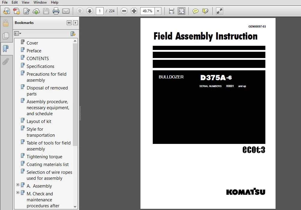
KOMATSU D375A-6 BULLDOZER Field Assembly Instruction Manual (SN:60001 & UP) KOMATSU D375A 6 – PDF Download
Original price was: $81.95.$27.95Current price is: $27.95.
- KOMATSU D375A-6 BULLDOZER Field Assembly Instruction Manual
- SERIAL NUMBER:60001 & UP
- PUBLICATION NUMBER:GEN00097-03
Instant PDF Download
Available immediately
Save to Your Device
Download & keep forever
Antivirus Scanned
100% virus-free
Trusted Worldwide
175,000+ customers
Description
KOMATSU D375A-6 BULLDOZER Field Assembly Instruction Manual (SN:60001 & UP) KOMATSU D375A 6
KOMATSU D375A-6 BULLDOZER FIELD ASSEMBLY INSTRUCTION MANUAL (SN:60001 & UP) KOMATSU D375A 6 – PDF DOWNLOAD:
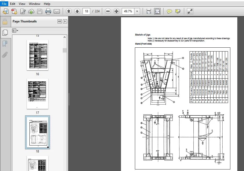
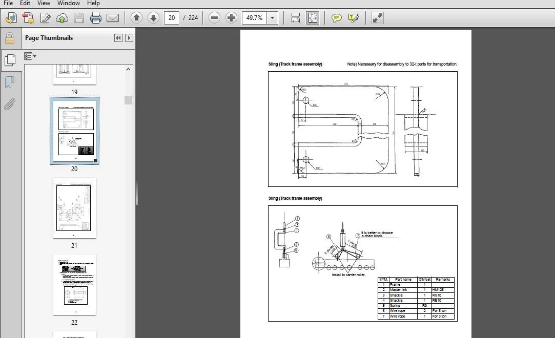
IMAGE PREVIEW:
DESCRIPTION:
KOMATSU D375A-6 BULLDOZER Field Assembly Instruction Manual (SN:60001 & UP) KOMATSU D375A 6
- Since this machine is large in size, it is divided into some units to meet the transportation conditions and regulations applied to the transporta- tion route when shipped from our factory. This manual describes how to assemble the units into the complete machine in the field. We hope that this machine will display its quality and you will use it safely according to the operation manual.
- Many units are large in size and heavy in weight and may be handled in a dangerous place or posture and many workers may have to work together to sling them with cranes. Accordingly, before starting the assembly work, the work supervisor is required to hold a safety meeting to oblige the workers to put on pro- tective gear and appoint a work leader and a crane work signal man and allot roles to all the workers for safe work.
- In particular, the above meeting is more important when worker of dif- ferent languages and customs work together. The following is a reference supervision system diagram. When the work equipment is installed, the engine must be operated. Accordingly, before installing the work equipment, inspect and main- tain the machine thoroughly. Note that this manual does not describe the whole specification of the machine but describes only the basic specification.
TABLE OF CONTENTS:
KOMATSU D375A-6 BULLDOZER Field Assembly Instruction Manual (SN:60001 & UP) KOMATSU D375A 6
Cover..............................................................................................  1
Preface............................................................................................  2
CONTENTS...........................................................................................  4
Specifications.....................................................................................  6
Precautions for field assembly.....................................................................  7
Disposal of removed parts..........................................................................  8
Assembly procedure, necessary equipment, and schedule..............................................  9
Layout of kit...................................................................................... 10
Style for transportation........................................................................... 11
Table of tools for field assembly.................................................................. 16
Tightening torque.................................................................................. 22
Coating materials list............................................................................. 27
Selection of wire ropes used for assembly.......................................................... 30
A.  Assembly....................................................................................... 32
	A-1 Installation of chassis.................................................................... 33
	A-2 Installation of undercover................................................................. 36
	A-3 Installation of pivot shaft................................................................ 37
	A-4 Installation of undercarriage.............................................................. 39
	A-5 Adding oil to recoil chamber and pivot chamber............................................. 66
	A-6.1 Installation of engine air inlet hood.................................................... 67
	A-6.2 Installation of engine air pre-cleaner (if equipped)..................................... 68
	A-7 Installing direction of exhaust pipe....................................................... 69
	A-8 Installation of blade lift cylinder........................................................ 70
	A-9 Installation of ripper..................................................................... 72
	A-10 Installation of track..................................................................... 79
	A-11 Assembly of blade......................................................................... 81
	A-12 Installation of blade..................................................................... 97
	A-13 Installation of operator's cab............................................................106
	A-14 Installation of rear monitor camera (if equipped).........................................124
	A-15 Installation of additional cab lights (if equipped).......................................128
	A-16 Installation of ROPS......................................................................130
	A-17 Installation of VHMS, ORBCOMM antenna.....................................................132
	A-18 Installation of revolving warning lamp to top of ROPS (if equipped).......................133
	A-19 Check track tension.......................................................................136
	A-20 Check fuel, coolant and lubricants........................................................138
	A-21 Bleeding air from hydraulic cylinders.....................................................140
	A-22 Lubricating...............................................................................141
	A-23 Installation of fuel quick charge piping (if equipped)....................................144
M. Check and maintenance procedures after completion of assembly...................................146
	M-1 Check and adjustment of operator's cab.....................................................147
	M-2 Inspection of machine monitor..............................................................154
	M-3 Checking operation of dual tilt mechanism (If equipped)....................................168
	M-4 Setting procedure for USER ADJUST MODE.....................................................169
	M-5 Setting procedure for maximum cooling fan speed............................................171
	M-6 Replacement of return filter (Replacement of standard filter -> special flushing parts)....172
	M-7 Flushing of hydraulic circuit, and bleeding air from hydraulic cylinders (Part 1)..........174
	M-8 Replacement of return filter (Replacement of special flushing parts -> standard filter)....175
	M-9 Bleeding air from hydraulic cylinders (Part 2).............................................177
APPENDIX 1. Installation procedure for spill guard (Installation by welding).......................178
APPENDIX 2. Precautions for initialization procedures for VHMS controller..........................190
Field assembly inspection report...................................................................210
PLEASE NOTE:
⦁ This is not a physical manual but a digital manual – meaning no physical copy will be couriered to you. The manual can be yours in the next 2 mins as once you make the payment, you will be directed to the download page IMMEDIATELY.
⦁ This is the same manual used by the dealers inorder to diagnose your vehicle of its faults.
⦁ Require some other service manual or have any queries: please WRITE to us at [email protected]




Donald –
I received what I ordered and was exactly what I was looking for to diagnose what I was working on.