
Komatsu D375A-6 Bulldozer Shop Manual SEN05006-06 PDF Download
Original price was: $39.95.$24.95Current price is: $24.95.
Complete shop manual for Komatsu D375A-6 bulldozer serial numbers 60001 and up covering structure, testing, troubleshooting and disassembly procedures.
Description
File Details
- Manual Type: Shop Manual
- Brand: Komatsu
- Model: D375A-6 Bulldozer
- Language: English
- Page Count: 542
- Publication Number: SEN05006-06
- Revision: 6th revision
- Serial Range: 60001 and up
- File Format: PDF
Chapters Covered
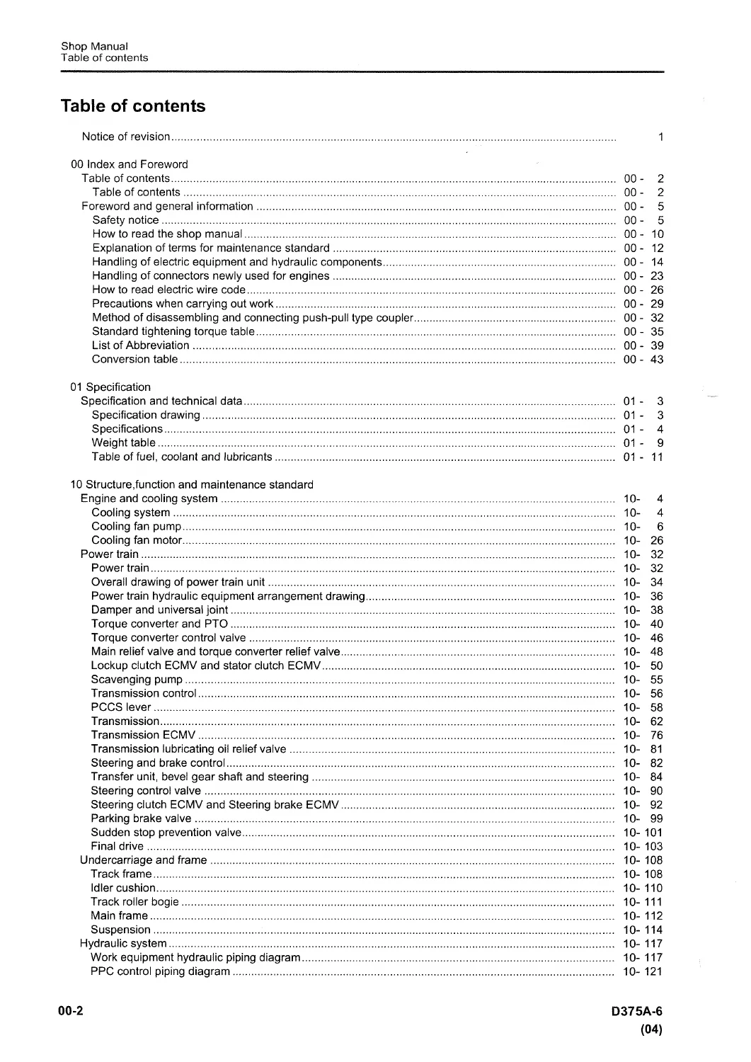
- 00 Index and Foreword – Table of contents, safety notice, how to read the shop manual, abbreviations, conversion tables
- 01 Specification – Specification and technical data, weight table, table of fuel, coolant and lubricants
- 10 Structure, function and maintenance standard – Engine and cooling system, power train, undercarriage and frame, hydraulic system, work equipment, cab, electrical system including monitor, VHMS and ORBCOMM
- 20 Standard value table – Standard service value table for engine and machine
- 30 Testing and adjusting – Tools, engine and cooling system tests, power train, undercarriage, hydraulic system, work equipment, cab, electrical system special functions
- 40 Troubleshooting – General information, failure codes table, troubleshooting by failure code for power train, electrical, hydraulic and engine systems
- 50 Disassembly and assembly – Engine and cooling system, power train, undercarriage and frame, hydraulic system, work equipment, cab and electrical system removal and installation procedures
- 60 Maintenance Standard – Engine mount, power train components, undercarriage, hydraulic valves and cylinders, work equipment
- 80 Appendix – Air conditioner system details and troubleshooting
- 90 Diagrams and Drawings – Hydraulic diagrams, electrical circuit diagrams
This comprehensive shop manual provides technicians with detailed guidance on the structure and function of major systems on the D375A-6, complete with maintenance standards, testing procedures, extensive failure code diagnostics and step-by-step disassembly and assembly instructions for engine, transmission, final drives, undercarriage, hydraulics and work equipment.
Key Systems and Procedures
The manual details the power train including torque converter, TORQFLOW transmission, steering and final drives. Hydraulic system coverage includes work equipment pumps, control valves, PPC valves and cylinders for blade and ripper. Electrical content spans engine control, machine monitor, sensors and vehicle health monitoring. Testing sections cover compression, fuel pressure, oil pressures, track tension and hydraulic drift checks. Troubleshooting addresses hundreds of specific failure codes for clutches, brakes, sensors and controllers along with symptom-based diagnosis for engine, travel and work equipment issues.
Safety and Service Information
Safety notices emphasize proper use of tools, lifting equipment, pressure release and personal protective equipment. Standard torque tables for bolts, hoses and fittings are provided along with coating materials and special tools lists. Procedures include air bleeding for hydraulic systems and precautions for handling high-pressure components.
Testing and Adjusting Coverage
Section 30 provides detailed procedures for testing engine speed, intake air pressure, exhaust temperature and gas color, valve clearance adjustment, compression pressure, blow-by pressure, engine oil pressure, EGR valve drive oil pressure, fuel pressure, leakage from pressure limiter, air bleeding from fuel circuit, fan speed and circuit oil pressure. Power train tests include oil pressure checks, transmission output speed sensor adjustment, brake performance tests and emergency escape methods. Hydraulic testing covers work equipment oil pressure, control circuit main pressure, PPC valve output and play, cylinder leakage and hydraulic drift diagnosis for blade and ripper. Electrical special functions of the machine monitor (EMMS) and controller replacement procedures are included.
Troubleshooting Depth
The troubleshooting section is extensive with general information on sequence of events, checks before troubleshooting, classification of procedures, failure codes table and phenomena mapping. Specific failure code diagnosis covers battery charge, lock up clutch slip, transmission clutch abnormalities, fill high/low for forward reverse and speed clutches, brake thermal load, sensor errors for charge air, throttle, oil pressure, coolant temperature, fuel temperature, rail pressure, EGR valve, injector circuits, CAN communication losses, relay disconnections and short circuits, switch signal disagreements and many more. Electrical system E-mode troubleshooting addresses engine starting issues, preheater, monitor displays, gauges, lamps, wipers, priming pump and gear shift problems. Hydraulic and mechanical H-mode covers lack of power, travel issues, turning problems, brake function, torque converter lockup, work equipment speed and drift. Engine S-mode diagnoses hard starting, lack of power, black smoke, oil consumption, overheating and abnormal noise.
Disassembly and Assembly Guidance
Section 50 includes general information, coating materials list, special tools list and sketches. Detailed removal and installation cover fuel supply pump, injectors, cylinder head, radiator guard, cooling assembly, engine assembly, fan drive, fuel tank, damper, power train unit, PTO, torque converter, TORQFLOW transmission, steering case, pumps, final drive, track frame, idler, recoil spring, track roller, carrier roller, bogie, track shoe, pivot shaft, equalizer bar, hydraulic tank, work equipment pump, fan pump, control valve, PPC valves, hydraulic cylinders, blade, giant ripper, ROPS, operator cab, floor frame, air conditioner, and various controllers and monitor.
Maintenance Standards and Diagrams
Section 60 provides maintenance standards for engine mount, cooling fan pump and motor, power train unit, damper and universal joint, torque converter and PTO, lockup clutch ECMV, scavenging pump, transmission, power train and lubrication pump, transfer and bevel gear shaft, steering control valve, parking brake valve, final drive, sprocket, track frame, idler, track roller, carrier roller, bogie, track shoe, main frame, suspension, PPC valve, hydraulic cylinder, quick drop valve, work equipment pump, control valve, self-pressure reducing valve, cylinder stay, blade and cutting edge, ripper. Appendix 80 covers air conditioner refrigerant caution, configuration, testing and troubleshooting charts for the air conditioner system. Section 90 includes hydraulic diagrams with symbols, power train hydraulic circuit diagram, work equipment hydraulic piping, and electrical circuit diagrams with symbols and full wiring information.
Technicians gain complete support for diagnosing complex electronic and hydraulic interactions on this large dozer, performing overhauls of major components and maintaining the machine to original performance standards using the listed special tools and correct torque values.
The foreword section explains how to use the manual, standard tightening torque tables for various bolts, hoses, O-ring bosses and engine series fasteners, methods for push-pull type couplers, and general precautions for removal, installation and completing work including air bleeding sequences for hydraulic cylinders after reassembly.
Get Your Manual Now
Use this shop manual to perform accurate testing, diagnose failure codes correctly, follow proper disassembly sequences and apply the right maintenance standards on your Komatsu D375A-6. Correct procedures prevent damage and keep the machine productive. Instant PDF download after payment, no shipping required, viewable on any device and ready to print for workshop use.

Reviews
There are no reviews yet.