
Trusted Business
Verified & Licensed
Virus Free Files
100% Safe Downloads
Secure Payment
SSL Protected
Instant Delivery
Available Immediately
Sale!


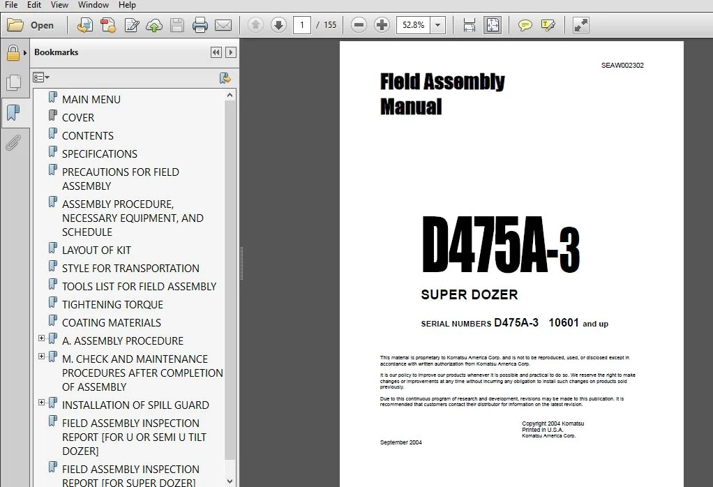
KOMATSU D475A-3 SUPER DOZER FIELD ASSEMBLY MANUAL (SN:10601 & UP) KOMATSU D475A-3 – PDF DOWNLOAD
Original price was: $73.95.$26.95Current price is: $26.95.
- KOMATSU D475A-3 SUPER DOZER FIELD ASSEMBLY MANUAL
- Serial Number:10601 & UP
- Publication Number:SEAW002302
Instant PDF Download
Available immediately
Save to Your Device
Download & keep forever
Antivirus Scanned
100% virus-free
Trusted Worldwide
175,000+ customers
Description
KOMATSU D475A-3 SUPER DOZER FIELD ASSEMBLY MANUAL (SN:10601 & UP) KOMATSU D475A-3
KOMATSU D475A-3 SUPER DOZER FIELD ASSEMBLY MANUAL (SN:10601 & UP) KOMATSU D475A-3 – PDF DOWNLOAD:
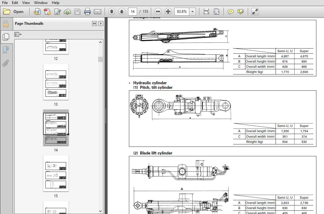
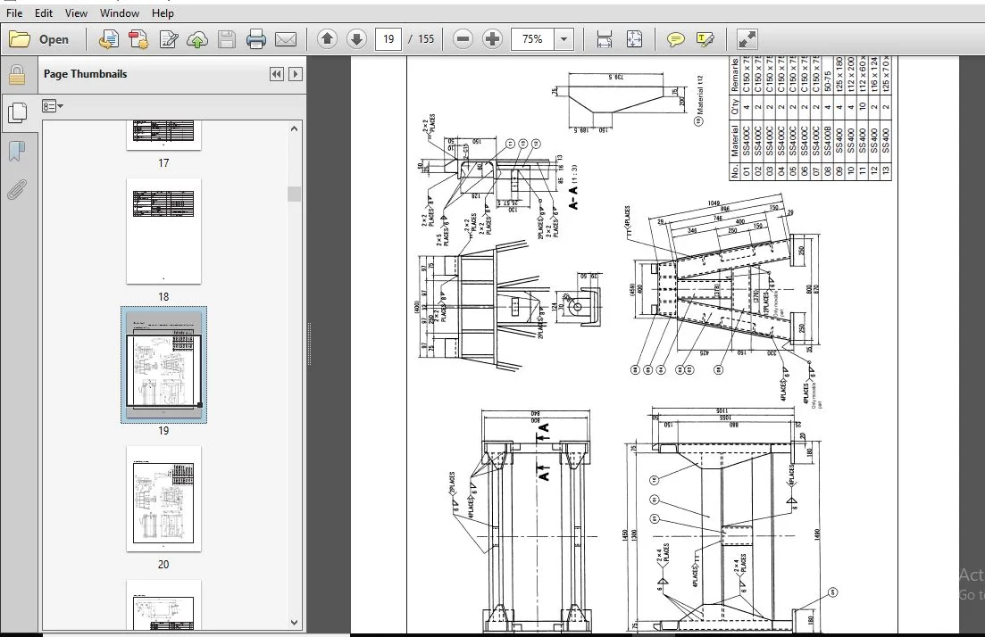
IMAGE PREVIEW:
DESCRIPTION:
KOMATSU D475A-3 SUPER DOZER FIELD ASSEMBLY MANUAL (SN:10601 & UP) KOMATSU D475A-3
- You are required to execute full inspection and maintenance before starting the engine and assembling the work equipment. Since the work is often carried out in dangerous places and positions by a team, hold a safety meeting in advance and appoint a crane director, work leader, etc. so that the all member can work safely.
- When the work is carried out in an overseas country, difference in language, customs, etc. lowers safety. Accordingly, the field liaison man and work supervisor must examine the above point and take necessary measures. We hope that the all members will cooperate with each other and assemble the work equipment quickly in the field, observing the safety, quality, and delivery time.
TABLE OF CONTENTS:
KOMATSU D475A-3 SUPER DOZER FIELD ASSEMBLY MANUAL (SN:10601 & UP) KOMATSU D475A-3
MAIN MENU......................................................................................  0
COVER..........................................................................................  1
CONTENTS.......................................................................................  4
SPECIFICATIONS.................................................................................  6
PRECAUTIONS FOR FIELD ASSEMBLY.................................................................  9
ASSEMBLY PROCEDURE, NECESSARY EQUIPMENT, AND SCHEDULE.......................................... 10
LAYOUT OF KIT.................................................................................. 11
STYLE FOR TRANSPORTATION....................................................................... 12
TOOLS LIST FOR FIELD ASSEMBLY.................................................................. 17
TIGHTENING TORQUE.............................................................................. 24
COATING MATERIALS.............................................................................. 28
A. ASSEMBLY PROCEDURE.......................................................................... 30
	A-1 INSTALLATION OF UNDERCARRIAGE.......................................................... 31
	A-2 INSTALLATION OF RIPPER................................................................. 43
	A-3 INSTALLATION OF TRACKS................................................................. 46
	A-4 ADDING OIL TO PIVOT CHAMBER............................................................ 48
	A-5 INSTALLATION OF RIPPER SHANK........................................................... 49
	A-6 INSTALLATION OF BLADE LIFT CYLINDER.................................................... 50
	A-7 INSTALLATION OF TILT HOSES AND TRUNNION................................................ 52
	A-8 ASSEMBLY OF BLADE...................................................................... 55
	A-9 ADJUSTMENT OF ARM JOINT (U-BLADE)...................................................... 67
	A-10 INSTALLATION OF BLADE................................................................. 68
	A-11 INSTALLATION OF COUNTERWEIGHT......................................................... 70
	A-12 INSTALLATION OF OPERATOR'S CAB........................................................ 71
	A-13 INSTALLATION OF ROPS.................................................................. 81
	A-14 ADJUSTMENT OF POTENTIOMETER ROD....................................................... 82
	A-15 PROCEDURE FOR ADJUSTING BLADE TILT LIMIT ANGLE........................................ 83
	A-16 METHOD OF CHECKING AUTO-RESET SYSTEM (SUPERDOZER)..................................... 92
	A-17 CHECK TRACK TENSION................................................................... 93
	A-18 CHECK OF OIL/COOLANT LEVEL IN EACH PART............................................... 95
	A-19 GREASING OF GREASING POINT............................................................ 97
	A-20 INSTALLATION OF ORBCOMM ANTENNA AND WIRING HARNESS....................................100
	A-21 REPLACEMENT OF RETURN FILTER (REPLACEMENT OF STANDARD FILTER WITH FLUSHING FILTER)....101
	A-22 INSTALLING DIRECTION OF EXHAUST PIPE..................................................104
	A-23 BLEEDING AIR FROM HYDRAULIC CYLINDERS.................................................105
M. CHECK AND MAINTENANCE PROCEDURES AFTER COMPLETION OF ASSEMBLY...............................106
	M-1 TESTING AND ADJUSTING OPERATOR'S CAB...................................................107
	M-2 ERROR CODE.............................................................................113
	M-3 FLUSHING HYDRAULIC CIRCUIT.............................................................119
INSTALLATION OF SPILL GUARD....................................................................120
	1. INTRODUCTION............................................................................120
	2. ADDITIONAL PARTS........................................................................120
	3. MANUFACUTURE DRAWING FOR SPILL GUARD....................................................121
		3-1. FOR SEMI-U-BLADE..................................................................121
		3-2. FOR FULL-U-BLADE..................................................................124
	4. INSTALLATION PROCEDURE..................................................................127
FIELD ASSEMBLY INSPECTION REPORT [FOR U OR SEMI U TILT DOZER]..................................128
FIELD ASSEMBLY INSPECTION REPORT [FOR SUPER DOZER].............................................142
PLEASE NOTE:
⦁ This is not a physical manual but a digital manual – meaning no physical copy will be couriered to you. The manual can be yours in the next 2 mins as once you make the payment, you will be directed to the download page IMMEDIATELY.
⦁ This is the same manual used by the dealers inorder to diagnose your vehicle of its faults.
⦁ Require some other service manual or have any queries: please WRITE to us at [email protected]




Jett Richard –