
Komatsu D475A-5 Crawler Dozer Shop Manual – S/N 20001 & Up PDF
Original price was: $44.95.$26.95Current price is: $26.95.
Complete Komatsu D475A-5 shop manual covering serial numbers 20001 and up. Engine, powertrain, hydraulics, undercarriage, testing, troubleshooting, disassembly and assembly for the D475A-5 crawler dozer.
Description
Komatsu D475A-5 Crawler Dozer Shop Manual (S/N 20001 & Up)
This Komatsu D475A-5 shop manual is the complete service and repair guide for D475A-5 crawler dozers from serial number 20001 and up. Whether you are a professional heavy equipment mechanic, a fleet maintenance technician, or a serious owner-operator, this D475A-5 shop manual gives you the procedures, specifications, and diagnostic information needed to keep this large dozer running correctly.
File Details
- Manual type: Shop Manual (Service and Repair)
- Brand: Komatsu
- Model: D475A-5 Crawler Dozer
- Serial number coverage: 20001 and up
- Engine: Komatsu SDA12V140E-1
- Document number: SEBM033703
- Language: English
- Page count: 1,194
- File format: PDF
Chapters Covered
- 01 GENERAL
- Foreword, safety notices, general precautions
- How to read the shop manual
- Hoisting instructions and wire rope data
- Connector handling procedures
- Coating materials and adhesives
- Standard tightening torque tables
- Electric wire code and conversion tables
- Specification drawings and dimensions
- Fuel, coolant and lubricant specifications
- 10 STRUCTURE, FUNCTION AND MAINTENANCE STANDARD
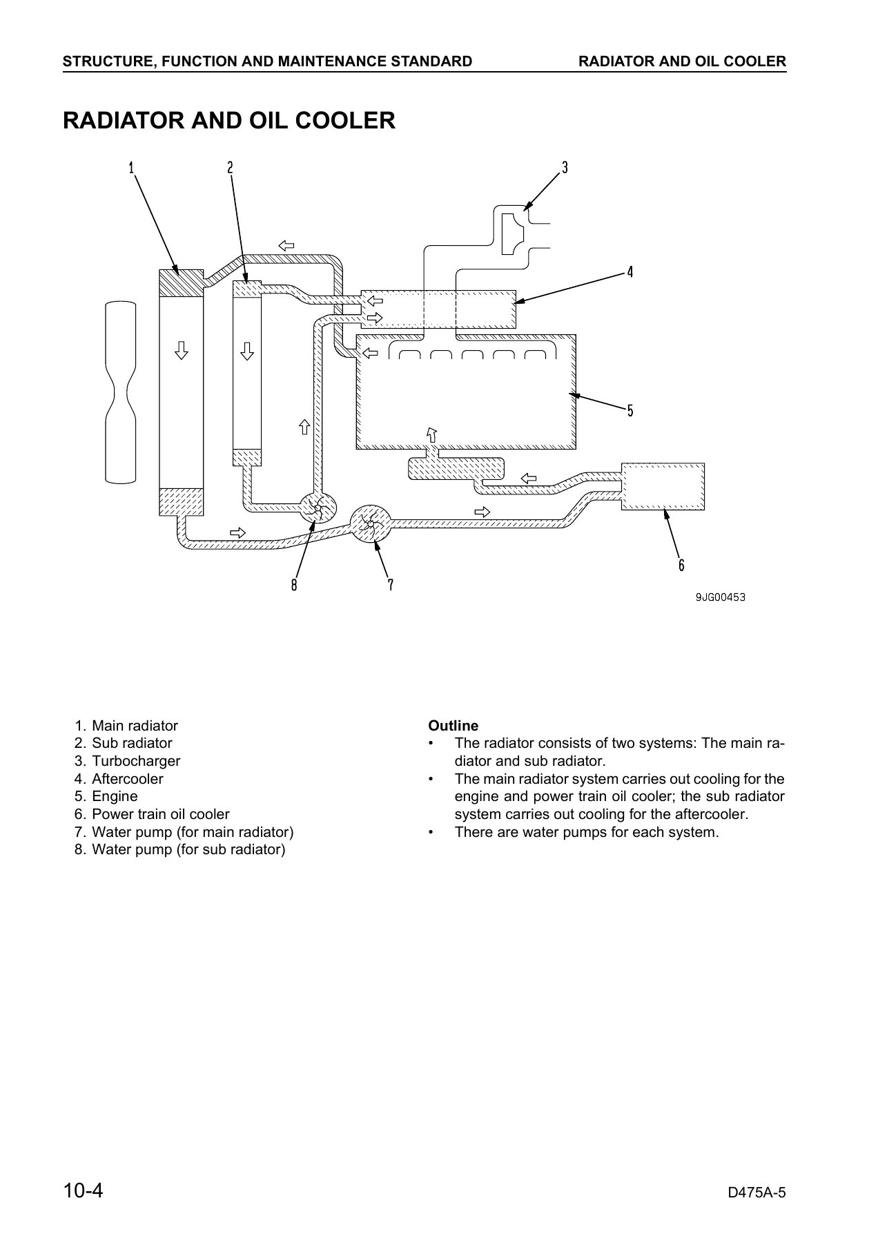
- Radiator and oil cooler
- Engine mount
- Power train hydraulic equipment arrangement
- Damper and universal joint
- Power train unit, torque converter and PTO
- Torque converter valve and lock-up control system
- Scavenging pump, transmission control, transmission ECMV
- Priority valve, lubricating oil relief valve
- Power train lubrication pump
- Steering and brake control
- Final drive, steering ECMV, parking brake valve
- Sprocket, track frame, recoil spring, idler
- Track roller, carrier roller, track shoe
- Main frame, suspension
- Work equipment hydraulic equipment arrangement
- Work equipment control and pump
- Cooling fan pump and motor
- PPC valve and electric lever
- Control valve, main relief valve, CLSS, unload valve
- LS pressure introduction, LS bypass plug
- Pressure compensation valve, blade lift valve
- Merge-divider valve, self-reducing pressure valve
- Pilot solenoid valve, hydraulic tank, accumulator
- Work equipment cylinder, piston valve, quick drop valve
- Blade control knob, pitch and dual solenoid valve
- Pin-puller hydraulic circuit and solenoid valve
- Cylinder stay, blade, ripper equipment
- Cab mount, cab, air conditioner
- Engine control, monitor system, sensors
- Mode selection system (SSC)
- Electrical equipment, steering electronic control system
- VHMS controller, communication controller/antenna
- 20 TESTING AND ADJUSTING
- Standard value tables for engine and chassis
- Measuring engine speed, intake air pressure, exhaust temperature
- Measuring exhaust gas color, compression pressure, blow-by pressure
- Measuring engine oil pressure, fuel injection timing
- Adjusting valve clearance, alternator belt, air conditioner belt
- Adjusting engine speed sensor, fuel control dial, decelerator pedal
- Measuring power train oil pressure
- Adjusting transmission speed sensor, brake pedal, parking brake lever
- Adjusting PCCS lever console position
- Emergency escape method when power train has trouble
- Adjusting idler clearance, inspecting sprocket wear
- Testing and adjusting track shoe tension
- Testing and adjusting work equipment oil pressure
- Testing and adjusting control circuit basic pressure
- Measuring PPC valve output pressure and solenoid valve output pressure
- Adjusting PPC valve play
- Measuring ripper pin puller solenoid valve output pressure
- Testing parts causing hydraulic drift, measuring internal leakage
- Releasing residual pressure, bleeding air from cylinders
- Adjusting blade lever stroke, ripper lever position, safety lock lever
- Measuring fan motor speed and fan circuit oil pressure
- Blade tilt control angle measurement procedures
- Testing and adjusting operator’s cab, adjusting blade
- Special functions of monitor panel (EMMS)
- Adjustment method of replaced controller
- VHMS controller initialization procedures
- Quick PM procedures and PM clinic service
- 30 DISASSEMBLY AND ASSEMBLY
- Method of using manual, precautions, special tool list
- Removal and installation of engine oil cooler, fuel injection pump
- Removal and installation of aftercooler core, nozzle holder
- Removal and installation of engine front and rear seals
- Removal and installation of cylinder head, fuel tank
- Removal and installation of main radiator, sub radiator
- Removal and installation of radiator guard, fan drive
- Removal and installation of fan motor pump, engine assembly
- Removal and installation of damper assembly
- Disassembly and assembly of damper assembly
- Removal and installation of power train unit
- Removal and installation of PTO, torque converter assembly
- Disassembly and assembly of torque converter
- Disassembly and assembly of PTO assembly
- Removal and installation of TORQFLOW transmission
- Disassembly and assembly of TORQFLOW transmission
- Disassembly and assembly of steering case
- Disassembly and assembly of steering clutch and brake
- Disassembly and assembly of transfer gear housing
- Removal and installation of power train pump
- Removal and installation of scavenging pump
- Removal and installation of torque converter oil cooler
- Removal and installation of torque converter valve
- Disassembly and assembly of torque converter valve
- Removal and installation of transmission control valve
- Disassembly and assembly of transmission control valve (ECMV)
- Removal and installation of steering control valve
- Disassembly and assembly of steering control valve
- Removal and installation of final drive assembly
- Disassembly and assembly of final drive assembly
- Removal and installation of track frame assembly
- Disassembly and assembly of idler assembly
- Removal and installation of recoil spring assembly
- Disassembly and assembly of recoil spring assembly
- Removal and installation of track roller assembly
- Disassembly and assembly of track roller assembly
- Removal and installation of carrier roller assembly
- Disassembly and assembly of carrier roller assembly
- Removal and installation of bogie assembly
- Disassembly and assembly of bogie assembly
- Removal and installation of No. 1 bogie assembly
- Removal and installation of track shoe assembly
- Overall disassembly and assembly of track shoe
- Press-fitting jig dimension table for link press
- Field disassembly and assembly of one link
- Disassembly and assembly of master link
- Removal and installation of pivot shaft assembly
- Removal and installation of equalizer bar
- Disassembly and assembly of equalizer bar bushing
- Removal and installation of hydraulic pump assembly
- Removal and installation of hydraulic valve assembly
- Disassembly and assembly of control valve
- Disassembly and assembly of merge-divider valve and self-reducing pressure valve
- Removal and installation of PPC relief valve
- Disassembly and assembly of hydraulic cylinder
- Disassembly and assembly of ripper pin-puller cylinder
- Removal and installation of blade assembly
- Disassembly and assembly of giant ripper assembly
- Removal and installation of ROPS guard
- Removal and installation of operator’s cab
- Removal and installation of floor frame
- Removal and installation of controller assembly
- Removal and installation of air conditioner condenser, compressor, unit
- Removal and installation of hood assembly
- Removal and installation of fan drive and fan motor
- 90 OTHERS
- Power train hydraulic circuit diagram
- Work equipment hydraulic circuit diagrams (single tilt, dual tilt, superdozer)
- Electrical circuit diagrams (monitor panel, engine controller, transmission controller, steering controller, VHMS controller, inside cab)
What This Komatsu D475A-5 Shop Manual Covers
The D475A-5 is a large crawler dozer with a operating weight of approximately 77,310 kg for the tractor alone, rising to over 102,000 kg with a semi-U tiltdozer, variable giant ripper, ROPS cab, and air conditioner. Its Komatsu SDA12V140E-1 engine is a 12-cylinder, 4-cycle, water-cooled, V-type, direct-injection unit with turbocharger and aftercooler, displacing 30.48 litres and producing 641 kW (860 HP) at 2,000 rpm. This shop manual covers the complete machine with the exception of the engine itself, which is covered in the separate 12V140-1 Series Engine Shop Manual as noted in the foreword.
The STRUCTURE, FUNCTION AND MAINTENANCE STANDARD chapter is the heart of this D475A-5 repair manual. It explains how each major system is built and how it operates, and it provides the maintenance standards, clearances, wear limits, and adjustment values you need to judge whether a component is serviceable. Systems covered include the radiator and oil cooler, engine mount, damper and universal joint, power train unit, torque converter and PTO, torque converter valve and lock-up control, scavenging pump, transmission and transmission ECMV, priority valve, steering and brake control, final drive, steering ECMV, parking brake valve, sprocket, track frame, recoil spring, idler, track roller, carrier roller, track shoe, main frame, suspension, work equipment hydraulics, work equipment pump, cooling fan pump and motor, PPC valve, control valve, main relief valve, CLSS, unload valve, LS pressure, pressure compensation valve, blade lift valve, merge-divider valve, self-reducing pressure valve, pilot solenoid valve, hydraulic tank, accumulator, work equipment cylinder, piston valve, quick drop valve, blade control knob, pin-puller circuit, ripper equipment, cab, air conditioner, engine control, monitor system, mode selection system, steering electronic control system, VHMS controller, and communication controller.
Engine and Powertrain Systems
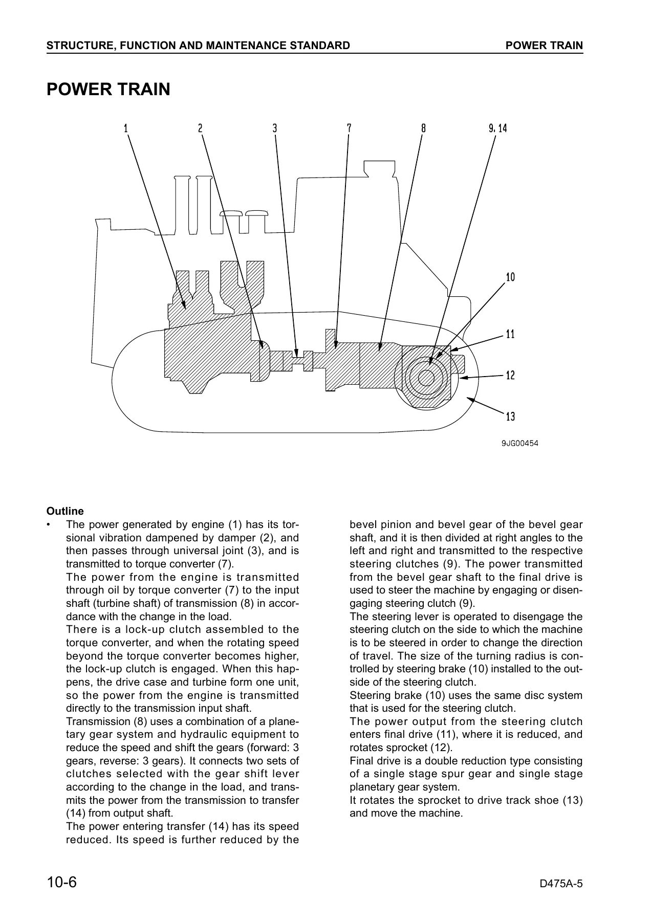
For the D475A-5 powertrain, this manual covers the damper assembly that absorbs torsional vibration from the engine, the universal joint that transmits power to the torque converter, and the torque converter itself, which is a 3-element, 1-stage, 1-phase type with a lock-up clutch and stator clutch. The lock-up control system is described in detail, including the conditions that lock and unlock the converter and the operation of the lock-up solenoid valve, selector valve, and modulating valves. The transmission is a planetary gear, multiple disc clutch, hydraulic, pump-forced lubrication unit with 3 forward and 3 reverse speeds, and the manual provides the clutch pressures, reduction ratios, and the ECMV operation table. The steering system uses wet multiple disc clutches and brakes with hydraulic actuation, and the manual explains the operation of the steering ECMV, sudden stop prevention valve, and parking brake valve. The final drive is a single-stage spur gear and single-stage planetary gear reduction unit, and the manual gives the complete disassembly and assembly procedure with bearing preload, backlash, and tooth contact adjustments.
Hydraulic and Work Equipment Systems
The work equipment hydraulic system on the D475A-5 is a CLSS (Closed center Load Sensing System) with a variable displacement pump, pressure compensation valves, and LS control. This D475A-5 service manual covers the work equipment pump (HPV125 + 125), the CO valve, LS valve, and LS-EPC valve, explaining how the pump swash plate angle is controlled to match load demand. The control valve is a 6-spool valve with a merge-divider valve, and the manual provides the complete disassembly and assembly procedure for each spool, the pressure compensation valves, the main relief valve, the unload valve, and the LS shuttle valves. The blade lift valve, blade tilt valve, ripper lift valve, and ripper tilt valve are all covered with their neutral, raise, lower, float, and tilt positions. The manual also covers the quick drop valve for the blade lift cylinder, the piston valve that cushions the stroke end, the accumulator that allows the work equipment to be lowered after the engine is stopped, and the PPC valve that provides pilot control. The cooling fan circuit, including the fan pump (LPV90 + 30), fan motor (LMF180), and the PC valve and EPC valve that control fan speed, is also described in full.
Testing, Adjusting and Troubleshooting
The TESTING AND ADJUSTING chapter of this Komatsu D475A-5 workshop manual provides standard value tables for both engine and chassis, giving the new-machine values and service limit values for speeds, pressures, temperatures, strokes, operating efforts, and clearances. The manual explains how to measure engine speed, intake air pressure (boost pressure), exhaust temperature, exhaust gas color, compression pressure, blow-by pressure, and engine oil pressure. It covers adjustment of valve clearance, fuel injection timing, alternator belt tension, air conditioner compressor belt tension, engine speed sensor, fuel control dial, and decelerator pedal. For the chassis, it covers power train oil pressure measurement, transmission speed sensor adjustment, brake performance testing, brake pedal and parking brake lever adjustment, PCCS lever console position adjustment, idler clearance, sprocket wear inspection, track shoe tension, work equipment oil pressure, control circuit basic pressure, PPC valve output pressure, and hydraulic drift testing. The monitor panel (EMMS) special functions are explained, including the service mode, adjustment mode, real-time monitoring mode, and dual display monitoring mode.
The TROUBLESHOOTING chapter is extensive and is divided into electrical system (E mode), hydraulic and mechanical system (H mode), and engine body (S mode). The electrical troubleshooting covers error codes for the transmission controller, steering controller, engine controller, and VHMS controller, with detailed circuit diagrams and connector pin numbers. The hydraulic and mechanical troubleshooting covers symptoms such as no force, no travel, steering problems, brake problems, torque converter lock-up problems, and work equipment speed and power problems. The engine troubleshooting covers starting performance, engine stops, hunting, lack of output, black exhaust gas, oil consumption, oil contamination, fuel consumption, coolant problems, oil pressure, oil level rise, overheating, abnormal noise, and vibration.
Disassembly and Assembly Procedures
The DISASSEMBLY AND ASSEMBLY chapter provides step-by-step procedures for removing, installing, disassembling, and assembling every major component of the D475A-5. Each procedure includes the special tools required, the tightening torques, the coating materials to use, and the precautions to observe. Major procedures include engine oil cooler, fuel injection pump, aftercooler core, nozzle holder, engine front and rear seals, cylinder head, fuel tank, main and sub radiators, radiator guard, fan drive, fan motor pump, engine assembly, damper, power train unit, PTO and torque converter, TORQFLOW transmission, steering case, steering clutch and brake, transfer gear housing, final drive, track frame, idler, recoil spring, track roller, carrier roller, bogie assembly, No. 1 bogie, track shoe, pivot shaft, equalizer bar, hydraulic pump, control valve, merge-divider valve, PPC relief valve, hydraulic cylinders, ripper pin-puller cylinder, blade assembly, giant ripper, ROPS guard, operator’s cab, floor frame, controller assembly, air conditioner components, hood assembly, and fan motor. The track shoe section includes the overall disassembly and assembly procedure, the press-fitting jig dimension table for the link press, field disassembly and assembly of one link, and disassembly and assembly of the master link.
Why This D475A-5 Shop Manual Matters
Working on a machine the size of the D475A-5 requires accurate information. A torque value that is too low can cause a track frame to shift, a pressure setting that is wrong can damage a transmission clutch, and an incorrect assembly procedure can lead to a final drive failure. This Komatsu D475A-5 shop manual gives you the specifications and procedures that Komatsu technicians use, so you can diagnose problems correctly, repair them safely, and return the machine to service with confidence. The testing and adjusting section alone is worth the investment, because it tells you exactly what to measure, what values are acceptable, and what to do when a reading is out of range. The troubleshooting section helps you find the root cause of a problem instead of replacing parts until something works.
IMAGES PREVIEW
This D475A-5 PDF manual is delivered instantly after purchase. There is no shipping, no waiting for a physical book, and no risk of a lost or damaged package. You can download it to your computer, tablet, or smartphone and access it whenever you need it. The PDF can be printed if you prefer a paper copy in the workshop, and you can print only the pages you need for a particular job. Whether you are servicing the hydraulic system, rebuilding the transmission, or adjusting the undercarriage, this Komatsu D475A-5 shop manual is the reference you will reach for again and again.


Reviews
There are no reviews yet.