
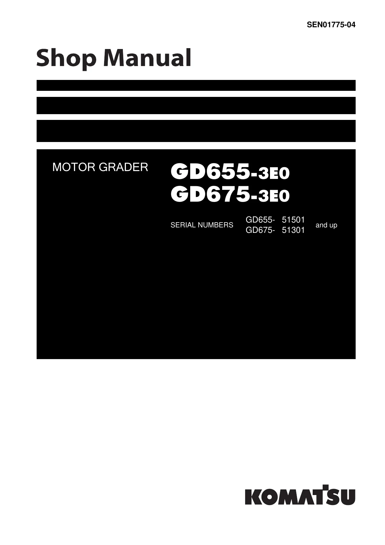
Komatsu GD655-3E0 GD675-3E0 Motor Grader Shop Manual SEN01775-04 – PDF Download
Original price was: $59.95.$39.95Current price is: $39.95.
Full Komatsu shop manual for GD655-3E0 and GD675-3E0 motor graders (SEN01775-04) — engine, power train, hydraulics, steering, brakes, electrical, testing, troubleshooting and disassembly.
Description
Komatsu GD655-3E0 and GD675-3E0 Motor Grader Shop Manual — SEN01775-04
This is the complete Komatsu shop manual for the GD655-3E0 and GD675-3E0 motor graders, issued by Komatsu under form number SEN01775-04. It covers both machines from serial GD655-51501 and up and GD675-51301 and up, and it is the same service documentation a Komatsu workshop technician uses on the floor: structure and function breakdowns, testing and adjusting procedures, standard value tables, troubleshooting by failure code, disassembly and assembly steps, and the wiring and hydraulic diagrams to go with them. Everything is written around the SAA6D114E-3 engine and the wet-clutch, eight-forward / four-reverse power shift transmission that these graders share.
File Details
- Manual type: Komatsu Shop Manual (SEN01775-04)
- Brand: Komatsu
- Models: GD655-3E0, GD675-3E0
- Serial numbers: GD655-51501 and up, GD675-51301 and up
- Engine: SAA6D114E-3 (6-cylinder, 114 x 135 mm, 8.27 L, turbocharged and aftercooled)
- Language: English
- File format: PDF
- Approx. pages: 1,029
Chapters Covered
- 00 Index and foreword
- 01 Specification
- 10 Structure, function and maintenance standard
- 20 Standard value table
- 30 Testing and adjusting
- 40 Troubleshooting
- 50 Disassembly and assembly
- 90 Diagrams and drawings
01 Specification
Opens with a general assembly drawing and a full machine specification sheet for each grader: overall length, height and width, wheelbase, tread, ground clearance, machine weight distribution front and rear, travel speeds in every gear (3.3 km/h in F1 up to 21.2 km/h in F6), maximum drawbar pull, gradeability, minimum turning radius and static stability. Engine data lists flywheel horsepower (134.2 – 149.2 kW / 1,900 rpm), maximum torque, no-load speeds and fuel consumption rate. The chapter also includes the weight table for major components and the fuel, coolant and lubricant selection chart keyed to ambient temperature.
10 Structure, Function and Maintenance Standard
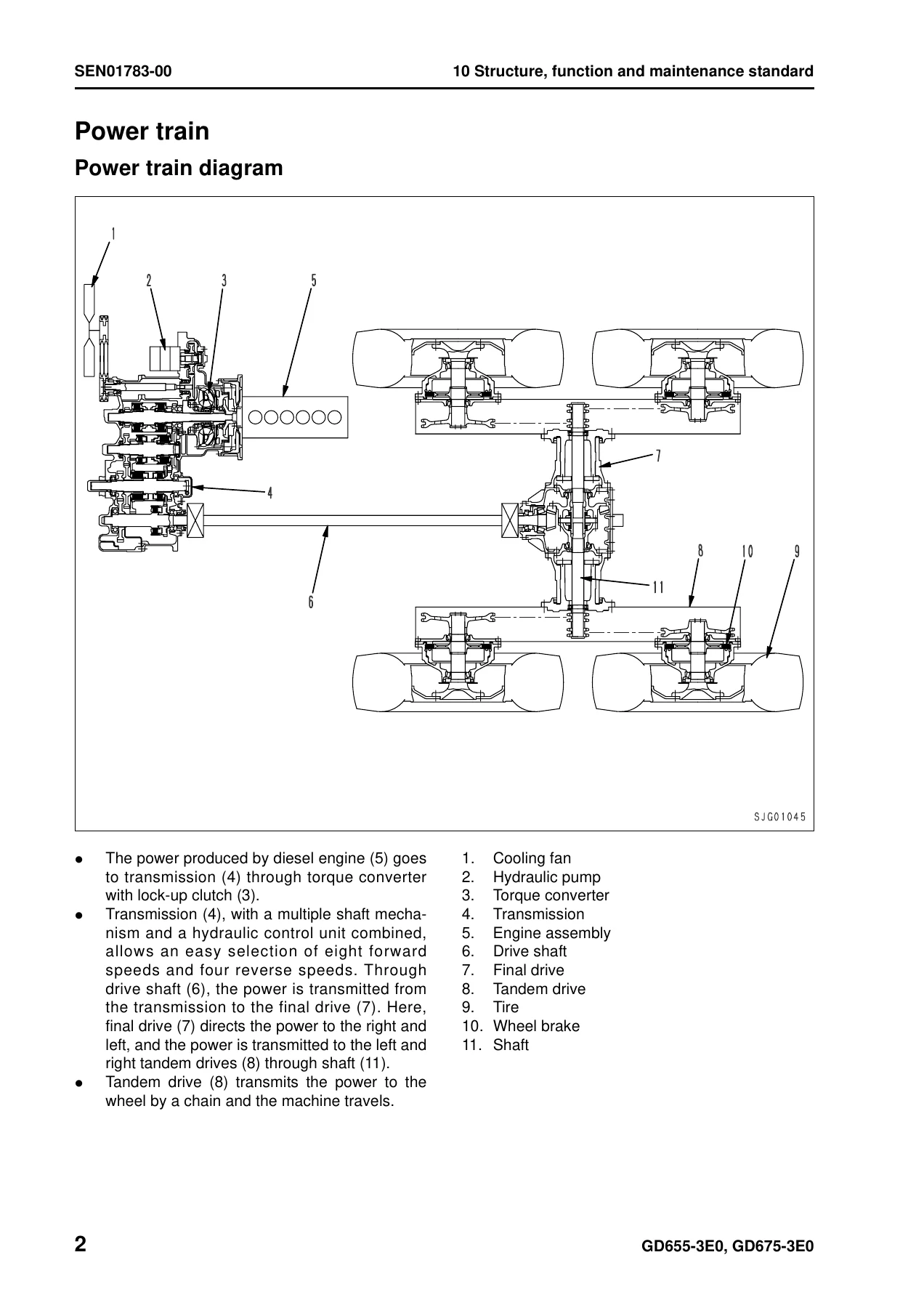
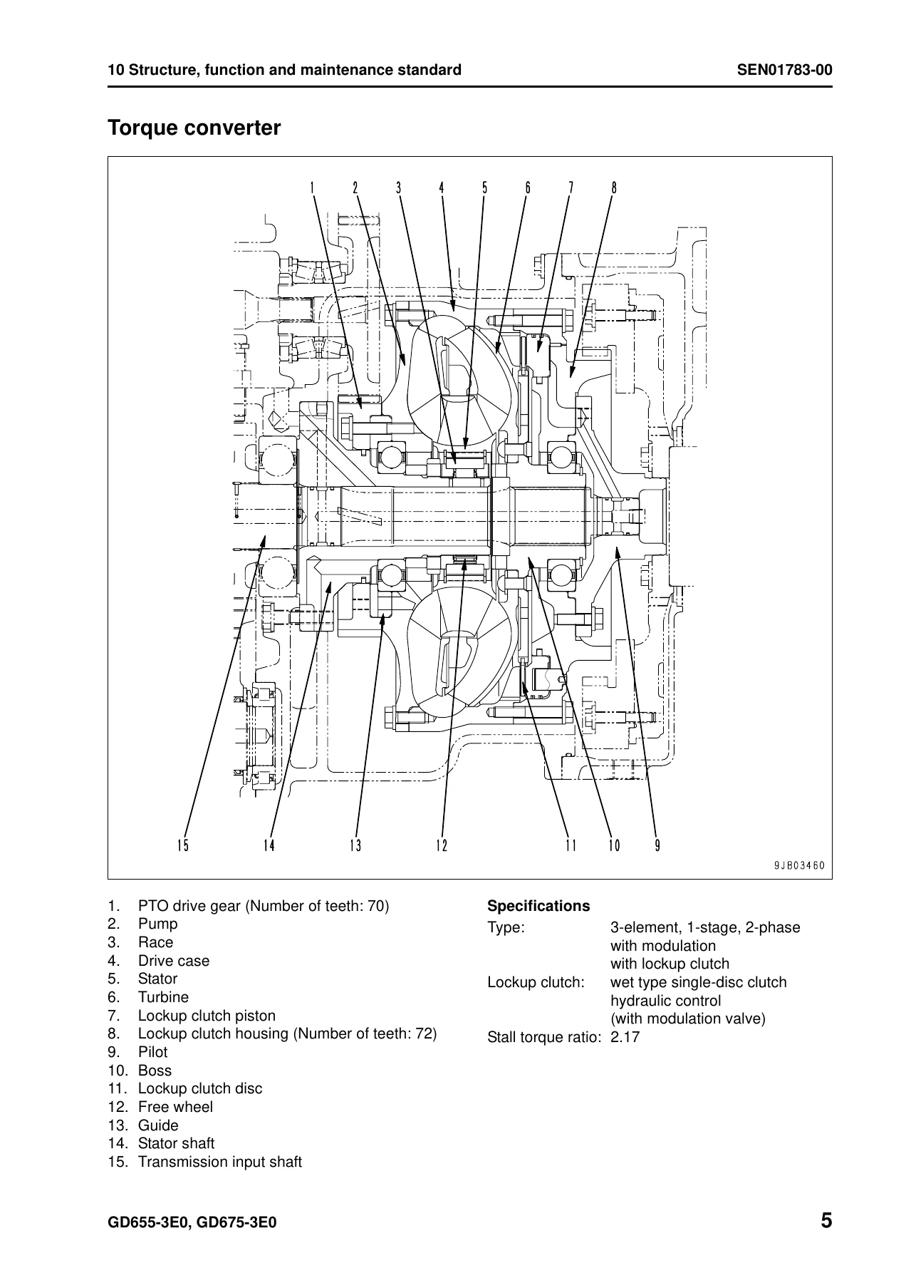
The largest section of the manual. It breaks the machine into engine and cooling, power train, steering, brake system, undercarriage and frame, hydraulic system, work equipment, cab, and electrical system. Each subsystem is described with cross-section illustrations, flow diagrams and function write-ups, then followed by maintenance standard tables giving standard size, tolerance, standard clearance, repair limit and the remedy (repair or replace). You will find the full torque converter, transmission, ECMV, main relief, final drive and tandem drive breakdowns here, plus the CLSS hydraulic pump, main control valves (left 5-spool and right 4-spool), priority valve, accumulator pressure governor valve, wheel brake, slack adjuster, parking brake, blade float and accumulator circuits, and the electrical architecture (transmission controller, machine monitor, sensors, communication controller, KOMTRAX terminal).
20 Standard Value Table
A single reference chapter that pulls together the standards you need to make pass/fail calls: engine rotation speeds, intake air pressure, exhaust temperature and gas color, valve clearance, blow-by pressure, engine oil pressure, hydraulic and power train oil pressures, torque converter stall speed, work equipment speeds, hydraulic drift limits and cylinder leakage limits for the GD655-3E0 and GD675-3E0.
30 Testing and Adjusting
Split into Part 1 and Part 2. Part 1 lists the special tools and then walks through every measurable item: exhaust color and temperature, boost pressure, blow-by, engine oil pressure, engine speed, fan and air conditioner belt tension, torque converter stall speed, clutch oil pressures, torque converter pressures, speed sensor adjustment, transmission flushing, brake disc wear, parking brake pad clearance and emergency release, accumulator charge pressure, work equipment oil pressure and LS differential pressure, PC valve adjustment, hydraulic air bleeding, internal cylinder leakage, differential lock oil pressure, steering and brake pressures, nitrogen charging of the brake and blade accumulators, circle guide clearance, slip clutch rotary device adjustment, potentiometer idle/full memorization, and initial learning for the transmission controller. Part 2 covers the machine monitor (EMMS) special functions, self-diagnosis of the gear shift lever, handling of the engine controller high-voltage circuit, moving the machine when the transmission valve fails, and the Pm-clinic check sheets.
40 Troubleshooting
Four sub-sections. The failure code table lists every code (CA, AB, B@, D, DA, DB, DD, DF, DG, DJ, DK, DL, DV, DW, DX, 2G) with its meaning, applicable controller, action code and history classification. Then come the code-by-code troubleshooting charts with cause, standard value in normal state and step-by-step test procedure, followed by E-mode (electrical symptoms such as no-start, no shift, brake, parking brake, lamp, gauge, buzzer and air conditioner faults), H-mode (hydraulic and mechanical symptoms such as no travel, slow travel, long shift lag, high torque converter oil temperature, wheel brake and work equipment faults), and S-mode (engine symptoms such as hard starting, no start, smoke, oil consumption, overheat, low oil pressure). This is the section that lets you diagnose a fault on the GD655-3E0 or GD675-3E0 from the symptom rather than by guessing.
50 Disassembly and Assembly
Step-by-step removal, disassembly, assembly and installation of every major component, with the coating material list, special tool list and special tool sketches. Covered assemblies include the fuel supply pump, fuel injectors, cylinder head, engine front and rear seals, complete engine, fuel / hydraulic / coolant tank assembly, air conditioner condenser, oil cooler, aftercooler, radiator, engine hood, engine and transmission assembly, transmission, torque converter, final drive, final brake case, side case, bevel gear, bevel gear shaft, bevel pinion, steering valve, work equipment control valves, hydraulic cylinders, blade, circle drawbar, blade circle gear, circle rotation gear (shear pin and slip clutch types), operator’s cab, floor frame, operator’s seat, cab glass, air conditioner unit, and the machine monitor and controllers.
90 Diagrams and Drawings
Power train hydraulic circuit diagram, brake hydraulic circuit, full hydraulic circuit diagrams (1/2 and 2/2), and electrical circuit diagrams (1/6 through 6/6) plus a connector arrangement diagram with pin counts and component names for every connector on the machine.
Why This Manual Matters for GD655-3E0 and GD675-3E0 Owners
Motor graders live or die by small tolerances: circle guide clearance, parking brake pad clearance, transmission clutch pressure, LS differential pressure, accumulator charge pressure. Get any of them wrong and you either damage expensive hardware or lose fine control on the blade. This manual gives you the exact Komatsu numbers, the exact Komatsu procedures, and the exact Komatsu safety instructions for every one of those adjustments. When a failure code appears on the machine monitor, the troubleshooting chapter tells you which circuit to check, what the normal reading is, and in what order to test — so you stop swapping parts on guesswork. When the transmission has to come out, the disassembly and assembly chapter shows the lifting points, the coating materials, the tightening torques and the sequence for every mounting bolt.
It covers engine and cooling, power train, steering, brake system, undercarriage and frame, hydraulic system, work equipment, cab and its attachments, and electrical system — the same scope a Komatsu service department would work from. Everything from a routine filter and oil change to an out-of-frame engine rebuild, from a sensor fault to a full transmission overhaul, is supported by procedures and values in this document.
IMAGES PREVIEW
Instant PDF Delivery
This Komatsu motor grader shop manual is delivered as a downloadable PDF the moment payment clears. There is no shipping, no waiting for a courier, and no physical binder to store. Open it on a laptop, a tablet or a phone in the workshop, print the pages you need for the job at hand, and take only those pages under the machine. Whether you are a Komatsu dealer technician, an independent heavy equipment mechanic, a fleet maintenance manager, or an owner-operator who wants to service the GD655-3E0 or GD675-3E0 properly, this SEN01775-04 shop manual is the reference to keep within reach. Add it to your library and stop chasing secondhand paper copies that arrive incomplete or unreadable — download it, keep it, use it.
Reviews
There are no reviews yet.