
Komatsu GD705A-4 Motor Grader Shop Manual PDF – Serial 23001 and Up
Original price was: $39.95.$23.95Current price is: $23.95.
Complete Komatsu GD705A-4 motor grader shop manual covering serial numbers 23001 and up. Includes structure and function, testing and adjusting, disassembly and assembly, hydraulic and electrical circuit diagrams for the S6D125-1 powered GD705A-4.
Description
Komatsu GD705A-4 Motor Grader Shop Manual – Complete Service Reference for Serial 23001 and Up
This Komatsu GD705A-4 shop manual is the complete technical reference for servicing and repairing the GD705A-4 motor grader, covering machines from serial number 23001 and upward. Prepared for Komatsu service personnel, it combines the structure and function of every major assembly, testing and adjusting procedures, disassembly and assembly instructions, and maintenance standards into one indexed document. Whether you are diagnosing a fault in the HYDROSHIFT transmission, adjusting the steering system, or overhauling the hydraulic cylinders, this manual provides the specifications and step-by-step procedures needed to carry out the work correctly.
The GD705A-4 mounts the Komatsu S6D125-1 diesel engine; for detailed engine overhaul, Komatsu refers technicians to the 6D125 Series Engine Shop Manual. This GD705A-4 shop manual itself covers the chassis and powertrain systems around the engine in five main chapters, with each chapter divided into the relevant component groups.
File Details
- Manual type: Shop Manual
- Brand: Komatsu
- Model: GD705A-4 Motor Grader
- Serial number: 23001 and up
- Engine: Komatsu S6D125-1 diesel engine
- Language: English
- Page count: 429
- File format: PDF
Chapters Covered
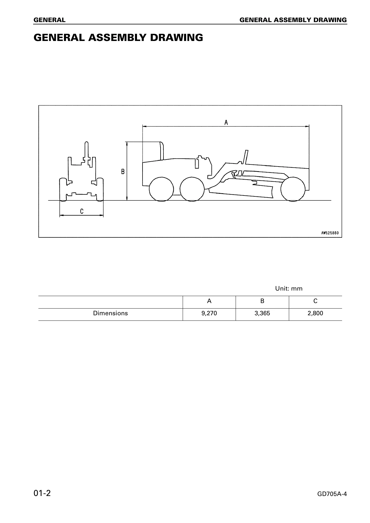
- 01 General – General assembly drawing, specifications, weight table
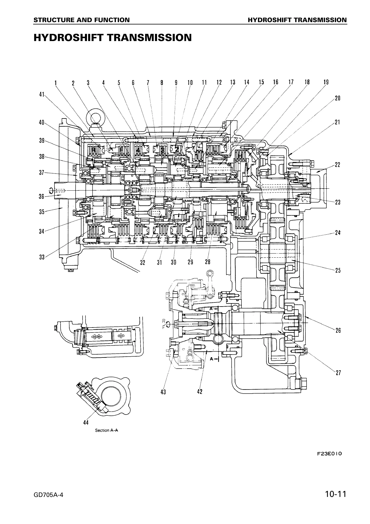
- 10 Structure, Function and Maintenance Standard – Radiator, fuel tank, power train, HYDROSHIFT transmission (planetary gear system, disc clutch, rotary clutch, control valve, priority valve, modulating valve, speed stage changing valve, inching valve), steering system, front axle, brakes, hydraulic pump, hydraulic cylinders, work equipment, blade and circle, ripper and scarifier
- 20 Testing and Adjusting – Standard value tables for the engine and chassis, testing and adjusting procedures, troubleshooting charts for electrical and mechanical systems
- 30 Disassembly and Assembly – Removal, installation, disassembly, and assembly of the HYDROSHIFT transmission, transmission pump, tandem and final drive assembly, wheel brake, front axle, steering pump, hydraulic control valves, and work equipment cylinders
- 90 Others – Hydraulic circuit diagrams (STD and DDV specifications), HYDROSHIFT transmission control circuit diagram, electrical circuit diagrams (1/2 and 2/2), air conditioner circuit diagram, and cab circuit diagram
The structure of the manual makes it practical for both planned maintenance and emergency repairs. The structure and function chapter explains how each component works and provides the maintenance standards for judging wear. The testing and adjusting chapter gives the measured values and adjustment procedures that keep the machine within specification. The disassembly and assembly chapter walks through each procedure with illustrations and torque values, and the others chapter supplies the circuit diagrams needed to trace hydraulic and electrical faults.
Key Systems Documented in Detail
The GD705A-4 is a motor grader with a planetary-type HYDROSHIFT transmission providing 8 forward and 8 reverse speeds. The manual explains the clutch combinations for each speed, the modulating and quick return valve operation that smooths gear changes, and the inching valve that allows fine control during travel. Detailed cross-sections show the arrangement of the forward, reverse, and speed clutches, the planetary gear sets, and the transfer case.
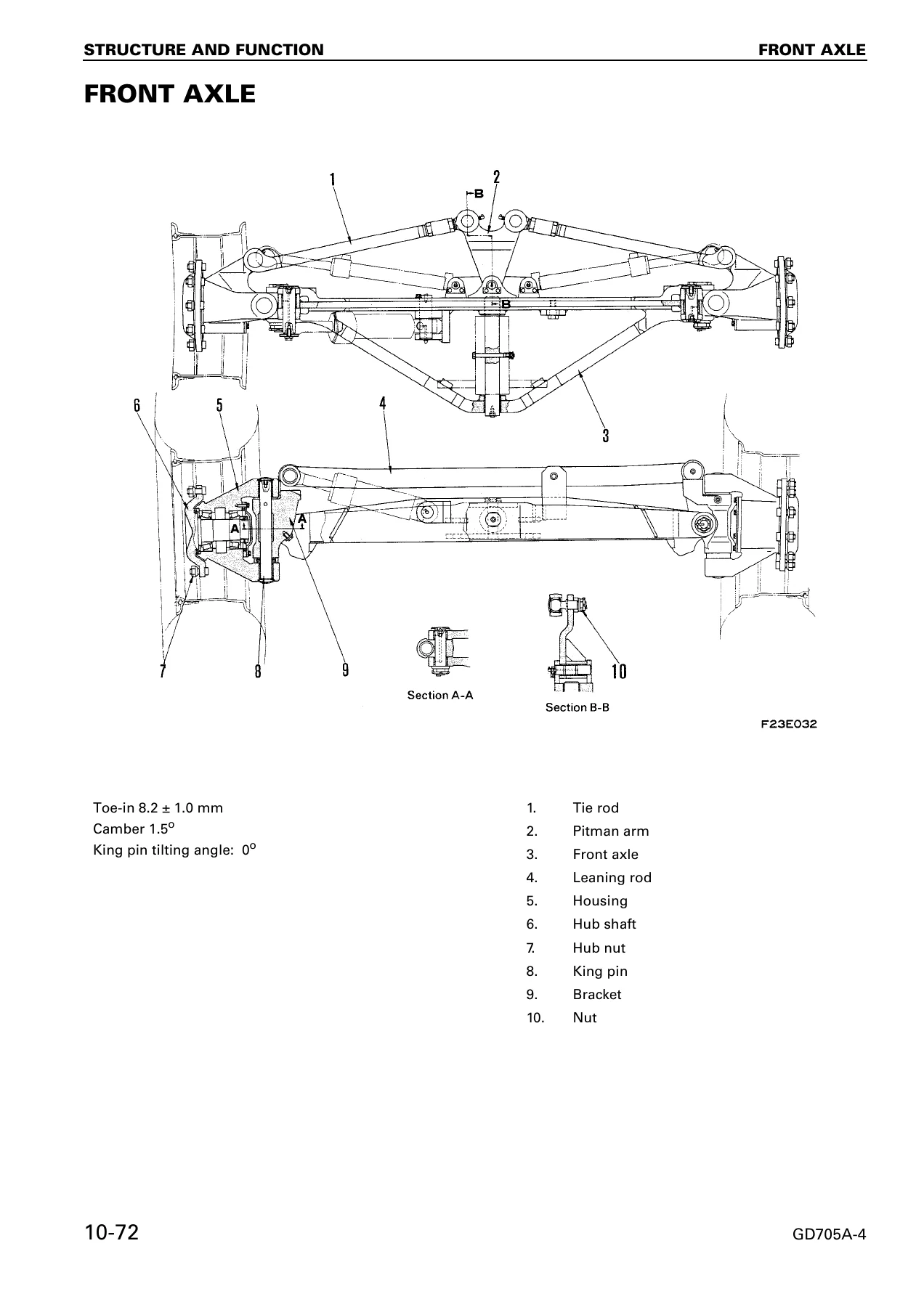
The steering system is fully hydraulic with an orbit-roll type steering valve. The manual covers the valve’s operation when the steering wheel is manipulated and when the oil pump malfunctions, along with the hand pump that allows emergency steering. Front axle alignment is documented including camber, toe-in, king pin inclination, and caster, with adjustment procedures and standard values.
The brake system combines air-over-hydraulic actuation with disc brakes at the wheels and a mechanical parking brake. The manual includes the air circuit components (compressor, governor, reservoir, relay valve, safety valve, pressure switches, and air drier), the brake valve operation in normal and failure modes, and the disc brake assembly with wear limits and adjustment.
Hydraulic system coverage includes the work equipment pumps, control valves, flow divider, dual demand valve (DDV), mode control valve, pilot check valves, and the full range of cylinders used on the blade, drawbar, leaning, articulate, power tilt, ripper, and scarifier. Testing and adjusting procedures give the relief pressures, drift limits, and operating speeds.
What the Testing and Adjusting Chapter Gives You
The testing and adjusting chapter opens with standard value tables for the engine and chassis, listing the acceptable ranges for engine speed, intake and exhaust temperatures, compression pressure, lubrication pressure, fuel injection timing, and cooling system operation. Chassis values cover lever strokes and operating forces, heat balance limits, tire pressures and alignment angles, steering wheel play, and work equipment speeds.
Individual testing and adjusting procedures follow for valve clearance, compression pressure, blow-by, fan belt tension, fuel injection timing, inching pedal stroke, transmission control lever stroke, F/R control cable, transmission control linkage, steering wheel play, tire play and air pressure, toe-in, parking brake lever stroke, brake disc wear, hydraulic oil pressure and temperature, work equipment control lever stroke, and hydraulic drift of the blade.
Troubleshooting is presented with charts correlating problems to causes, plus an electrical troubleshooting section (E mode) covering engine start failure, electric system failure, service meter, water temperature gauge, fuel gauge, and engine oil pressure gauge circuits.
Who This Shop Manual Is For
This GD705A-4 shop manual is written for service technicians, maintenance planners, and owners who need the correct procedures and specifications for the machine. It assumes familiarity with diesel engines, hydraulic systems, and heavy equipment repair practices, and it uses the standard Komatsu notation for safety, tightening torque, coating materials, and measurement units.
The general chapter includes safety notices, hoisting instructions, coating material lists, standard tightening torques, conversion tables, and unit conventions used throughout the manual. Technicians working on the GD705A-4 for the first time will find the structure and function explanations give the background needed to interpret the testing and disassembly procedures.
Get the Complete Komatsu GD705A-4 Shop Manual
With this Komatsu GD705A-4 shop manual PDF, you can carry out scheduled maintenance, diagnose hydraulic and electrical faults, adjust systems to specification, remove and reinstall major assemblies, and rebuild the HYDROSHIFT transmission, final drive, tandem drive, brakes, and work equipment cylinders. The manual gives the torque values, clearances, wear limits, and step-by-step sequences that prevent damage and ensure the machine returns to correct operation.
Correct procedures and specifications matter on a motor grader because the work equipment, steering, and powertrain all interact under load. Using the wrong clearance or torque can lead to premature failure, while following the manual’s testing and adjusting sequences keeps the machine productive and safe.
IMAGES PREVIEW
This Komatsu GD705A-4 motor grader shop manual is delivered as an instant PDF download after payment. There is no shipping, no waiting for a physical book, and no restriction on the device you use to read it. You can view it on a laptop or tablet in the workshop, print the pages you need for the job at hand, and search the contents to find the specification or procedure you are looking for. The PDF format keeps the diagrams, tables, and photographs legible whether you are working from a screen or a printed copy.

Reviews
There are no reviews yet.