Komatsu GTB45 GASOLINE ENGINE (ECU) Shop Manual TB45(CARB201 0)-BE1 PDF
$28.95
Komatsu GTB45 GASOLINE ENGINE (ECU) Shop Manual TB45(CARB201 0)-BE1 – PDF DOWNLOAD
FORKLIFT TRUCK MODEL
FG40ZTU/40TU/45TU/50ATU-10
FG40Z/35/40/45/50A-10
SERIAL No.
134756 and up
Description
Komatsu GTB45 GASOLINE ENGINE (ECU) Shop Manual TB45(CARB201 0)-BE1 – PDF DOWNLOAD
FILE DETAILS:
Komatsu GTB45 GASOLINE ENGINE (ECU) Shop Manual TB45(CARB201 0)-BE1 – PDF DOWNLOAD
Language : English
Pages :218
Downloadable : Yes
File Type : PDF
DESCRIPTION:
Komatsu GTB45 GASOLINE ENGINE (ECU) Shop Manual TB45(CARB201 0)-BE1 – PDF DOWNLOAD
FORKLIFT TRUCK MODEL
FG40ZTU/40TU/45TU/50ATU-10
FG40Z/35/40/45/50A-10
SERIAL No.
134756 and up
Description
• Observe the following precautions for safe and proper maintenance.
• Only qualified and appointed persons shall inspect, repair, or
adjust the vehicle.
• Keep the workplace and tools clean.
Safe Work
• Do not run the engine in a place which has no exhaust ducts and which is poorly ventilated.
• Ventilate the workplace well and do not place a combustible thing there. Take extreme care when handling a combustible
thing or a hazardous material such as gasoline.
• Dispose of the replaced oil, parts washing oil, etc. according to laws.
• When working on parts which become hot, rotary parts, or sliding parts, take care not to burn or injure yourself.
• When working in a pit or a closed place, ventilate it to discharge harmful materials in advance.
• Do not work on the vehicle jacked up. When working on it, support it by the specified parts on wood blocks, etc.
• When lifting up the vehicle, support it by the specified parts and apply a safety device.
• When removing a heavy part such as the engine, vehicle body, etc. take care not to drop it by unbalancing it.
• Do not smoke while maintaining the vehicle.
• When maintaining the vehicle, take off rings and necklace to prevent a short circuit in the electrical system.
• Before starting repair which does not need the battery power, turn the key switch OFF and disconnect the negative (–)
terminal of the battery
TABLE OF CONTENTS:
Komatsu GTB45 GASOLINE ENGINE (ECU) Shop Manual TB45(CARB201 0)-BE1 – PDF DOWNLOAD
FORKLIFT TRUCK MODEL
FG40ZTU/40TU/45TU/50ATU-10
FG40Z/35/40/45/50A-10
SERIAL No.
134756 and up
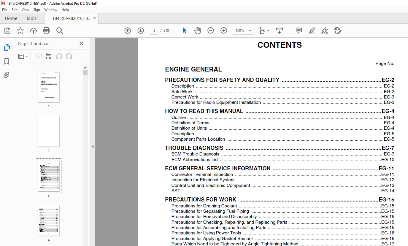
ENGINE GENERAL
PRECAUTIONS FOR SAFETY AND QUALITY EG-2
Description EG-2
Safe Work EG-2
Correct Work EG-3
Precautions for Radio Equipment Installation EG-3
HOW TO READ THIS MANUAL EG-4
Outline EG-4
Definition of Terms EG-4
Definition of Units EG-4
Description EG-5
Component Parts Location EG-5
TROUBLE DIAGNOSIS EG-7
ECM Trouble Diagnosis EG-7
ECM Abbreviations List EG-10
ECM GENERAL SERVICE INFORMATION EG-11
Connector Terminal Inspection EG-11
Inspection for Electrical System EG-12
Control Unit and Electronic Component EG-13
SST EG-14
PRECAUTIONS FOR WORK EG-15
Precautions for Draining Coolant EG-15
Precautions for Separating Fuel Piping EG-15
Precautions for Removal and Disassembly EG-15
Precautions for Checking, Repairing, and Replacing Parts EG-15
Precautions for Assembling and Installing Parts EG-15
Precautions for Using Power Tools EG-16
Precautions for Applying Gasket Sealant EG-16
Parts Which Need to be Tightened by Angle Tightening Method EG-17
PREPARATION EG-18
Special Service Tools EG-18
Service Parts EG-20
SERVICE DATA EG-21
Periodical Inspection EG-21
Standard, Repair Limit EG-23
Tightening Torque EG-24
ENGINE MECHANICAL
INTAKE MANIFOLD EM-2
Component Parts Location EM-2
Removal and Installation of Intake Manifold EM-3
Removal and Installation of Air Horn Bolt EM-3
Inspection EM-3
EXHAUST MANIFOLD EM-4
Component Parts Location EM-4
Removal and Installation EM-4
2
OIL PAN AND OIL STRAINER EM-6
Component Parts Location EM-6
Removal and Installation EM-6
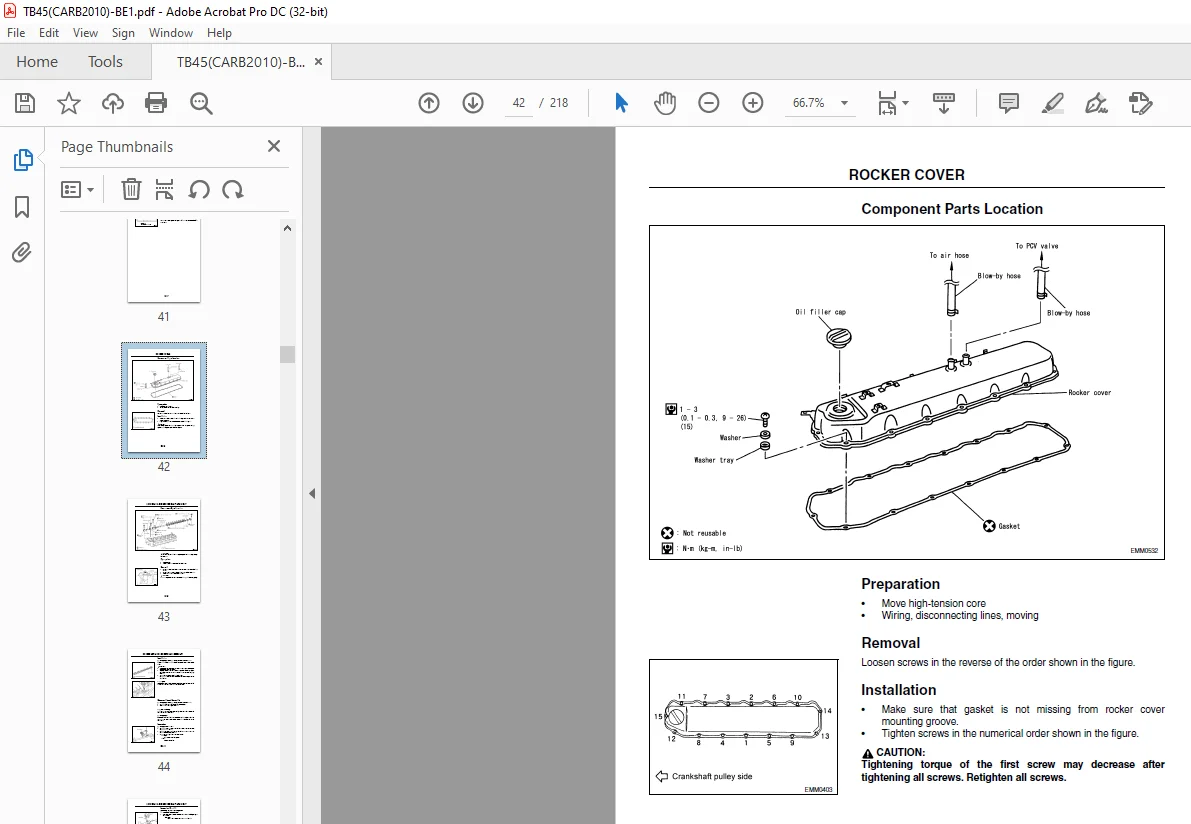
ROCKER COVER EM-8
Component Parts Location EM-8
Preparation EM-8
Removal EM-8
Installation EM-8
ROCKER ARM AND ROCKER SHAFT ASSEMBLY EM-9
Component Parts Location EM-9
Preparation EM-9
Removal EM-9
Installation EM-10
Disassembly and Assembly EM-10
Inspection EM-10
CYLINDER HEAD EM-12
Component Parts Location EM-12
Preparation EM-12
Cylinder Head Auxiliary Bolt EM-13
Cylinder Head Bolt EM-13
Cylinder Head Bolt Washer EM-14
Cylinder Head Gasket EM-14
Cylinder Head Assembly EM-15
TIMING CHAIN EM-20
Component Parts Location EM-20
Removal EM-20
Installation EM-23
CYLINDER BLOCK EM-27
Component Parts Location EM-27
Disassembly EM-27
Selective-Fit Service Parts EM-31
Inspection After Disassembly EM-31
Assembly EM-44
ENGINE LUBRICATION
OIL PUMP LU-2
Component Parts Location LU-2
Disassembly and Assembly LU-2
Inspection LU-3
ENGINE COOLING SYSTEM
CHANGING ENGINE COOLANT LU-2
Draining Engine Coolant LU-2
Refilling Engine Coolant LU-2
WATER PUMP LU-3
Component Parts Location LU-3
Removal and Installation LU-3
Water Pump Inspection LU-3
3
THERMOSTAT LU-4
Component Parts Location LU-4
Removal and Installation LU-4
ENGINE CONTROL
PRECAUTIONS EC-3
General Precautions for Service Operations EC-3
On Board Diagnostic (OBD) System of Engine EC-4
Precaution EC-4
Special Service Tools EC-7
ENGINE CONTROL SYSTEM EC-8
Description EC-8
System Diagram EC-9
Sensors and Actuators Control Items EC-10
TROUBLE DIAGNOSIS EC-11
Trouble Diagnosis Procedure EC-11
Diagnosis Chart by Symptom EC-15
Locations of components EC-26
Circult Diagram EC-30
ECM Terminal Layout EC-31
ECM Input/Output Signal Specifications EC-34
SST EC-40
Self-diagnosis Function (without SST) EC-44
Service Tool EC-46
Method of indicating failure code with troubleshooting tool EC-47
Example of indication of failure code EC-48
Method of indicating failure code with meter panel EC-48
SST Reference Value in Data Monitor EC-49
Fail-Safe Function EC-50
ECM Input/Output Signal Specifications EC-51
Circuit Diagram EC-51
CRANKSHAFT POSITION SENSOR 1° (POS) EC-52
ECM Input/Output Signal Specifications EC-52
Circuit Diagram EC-52
CRANK ANGLE SENSOR 120° (REF) SIGNAL SYSTEM EC-53
ECM Input/Output Signal Specifications EC-53
Circuit Diagram EC-53
Component Parts Inspection EC-53
MASS AIR FLOW SENSOR SYSTEM EC-54
SST Data Monitor Display EC-54
ECM Input/Output Signal Specifications EC-54
Circuit Diagram EC-54
Component Parts Inspection EC-54
HEATED OXYGEN SENSOR SYSTEM EC-55
SST Data Monitor Display EC-55
ECM Input/Output Signal Specifications EC-55
Circuit Diagram EC-55
VEHICLE SPEED SENSOR SYSTEM EC-56
SST Data Monitor Display EC-56
ECM Input/Output Signal Specifications EC-56
Circuit Diagram EC-56
4
THROTTLE POSITION SENSOR SYSTEM EC-57
SST Data Monitor Display EC-57
ECM Input/Output Signal Specifications EC-57
Circuit Diagram EC-57
Component Parts Inspection EC-57
ACCELERATOR PEDAL POSITION SENSOR SYSTEM EC-58
SST Data Monitor Display EC-58
ECM Input/Output Signal Specifications EC-58
Circuit Diagram EC-58
INTAKE AIR TEMPERATURE SENSOR SYSTEM EC-59
SST Data Monitor Display EC-59
ECM Input/Output Signal Specifications EC-59
Circuit Diagram EC-59
Component Parts Inspection EC-59
IGNITION SYSTEM EC-60
SST Data Monitor Display EC-60
ECM Input/Output Signal Specifications EC-60
Circuit Diagram EC-60
Component Parts Inspection EC-60
FUEL INJECTOR SYSTEM (GASOLINE) EC-61
SST Data Monitor Display EC-61
ECM Input/Output Signal Specifications EC-61
Circuit Diagram EC-61
Component Parts Inspection EC-61
THROTTLE CONTROL MOTOR SYSTEM EC-62
ECM Input/Output Signal Specifications EC-62
Circuit Diagram EC-62
Component Parts Inspection EC-62
HEATED OXYGEN SENSOR HEATER SYSTEM EC-63
SST Data Monitor Display EC-63
ECM Input/Output Signal Specifications EC-63
Circuit Diagram EC-63
Component Parts Inspection EC-63
LPG INJECTOR SYSTEM EC-64
ECM Input/Output Signal Specifications EC-64
Inspection EC-64
LPG ASSISTANCE INJECTOR SYSTEM EC-65
ECM Input/Output Signal Specifications EC-65
Circuit Diagram EC-65
Component Parts Inspection EC-65
LPG FUEL PRESSURE SENSOR SYSTEM EC-66
ECM Input/Output Signal Specifications EC-66
Circuit Diagram EC-66
MAP SENSOR SYSTEM EC-67
ECM Input/Output Signal Specifications EC-67
Circuit Diagram EC-67
Component Parts Inspection EC-67
FUEL CUT FUNCTION EC-69
Inspection Procedure EC-69
5
INTERCEPTION VALVE SYSTEM EC-70
SST Data Monitor Display EC-70
ECM Input/Output Signal Specifications EC-70
Circuit Diagram EC-70
FUEL CHANGING SWITCH SYSTEM EC-71
SST Data Monitor Display EC-71
ECM Input/Output Signal Specifications EC-71
Circuit Diagram EC-71
BLOW-BY GAS REDUCING DEVICE EC-72
System Chart EC-72
Removal and Installation of Blow-by Control Valve EC-72
Inspection of Blow-by Control Valve EC-72
ECM COMPONENTS EC-73
ECM EC-73
Crankshaft Position Sensor (Integrated Into the Distributor) EC-73
Mass Air Flow Sensor EC-73
Engine Coolant Temperature Sensor EC-73
Heated Oxygen Sensor (With Heated Oxygen Sensor Heater) EC-74
Throttle Position Sensor (Electric Throttle Control Actuator Assembly) EC-74
LPG Injector Holder EC-75
Map Sensor EC-75
SERVICE DATA AND SPECIFICATIONS (SDS) EC-76
Standard, Repair Limit EC-76
ENGINE FUEL SYSTEM
FUEL SYSTEM FL-2
Description FL-2
Component Parts Location FL-2
Gasoline Specification FL-2
LPG Specification FL-3
Specification for Combined Gasoline and LPG FL-3
FUEL INJECTOR (GASOLINE AND COMBINED USE) FL-4
Preparation FL-4
Fuel Hose FL-4
Fuel Tube and Fuel Injector FL-4
Inspection FL-6
LPG PARTS FL-7
LPG Device (Specifications for LPG and Gasoline/LPG) FL-7
Injector Holder FL-9
Vaporizer FL-12
ENGINE ELECTRICAL SYSTEM
STARTING SYSTEM EL-2
Component Parts Location EL-2
Starter Motor EL-2
STARTING MOTOR EXPRODED EL-3
6
MAINTENANCE OF STARTER EL-4
Starter Motor EL-4
Armature Coil EL-4
Data related to brush commutators EL-4
CHARGING SYSTEM EL-5
Component Parts Location EL-5
PROCEDURE FOR DISASSEMBLING AND INSPECTING THE ALTERNATOR EL-6
Component Parts Location EL-6
Disassembly EL-7
Inspection EL-9
HIGH-TENSION CABLE EL-13
Assembly EL-13
ENGINE TUNE-UP
VALVE CLEARANCE ET-2
Description ET-2
Inspection ET-2
Adjustment ET-3
ENGINE DRIVE BELT ET-4
Inspection ET-4
Belt Tension Adjustment ET-5
ENGINE OIL ET-6
Inspection ET-6
Replacement ET-7
Oil Filter Replacement ET-8
COMPRESSION PRESSURE ET-10
Inspection ET-10
SPARK PLUG ET-11
Removal and Installation ET-11
Inspection After Removal ET-11
IMAGES PREVIEW OF THE MANUAL:
S.M 15/12/24