
Komatsu HD1500-8 Dump Truck Shop Manual – SEN06630-02 PDF Workshop Guide
Original price was: $44.95.$27.95Current price is: $27.95.
Complete Komatsu HD1500-8 dump truck shop manual (SEN06630-02) covering serial numbers 81001 and up. 2730-page PDF workshop guide with engine, transmission, brake, hydraulic, and electrical service procedures, specifications, troubleshooting, and disassembly instructions.
Description
Komatsu HD1500-8 Dump Truck Shop Manual
This is the complete Komatsu HD1500-8 shop manual, document number SEN06630-02, covering dump trucks with serial numbers 81001 and up. The manual spans 2730 pages and provides comprehensive technical information for servicing, repairing, and maintaining the HD1500-8 mining dump truck. Everything from engine overhaul to hydraulic troubleshooting is documented with specifications, procedures, and reference values.
File Details
- Manual type: Shop Manual (Workshop Manual)
- Brand: Komatsu
- Model: HD1500-8
- Serial numbers: 81001 and up
- Document number: SEN06630-02
- Language: English
- Page count: 2730
- File format: PDF
Chapters Covered
- 00 INDEX AND FOREWORD — Abbreviations, foreword, safety, basic information, how to read the shop manual, safety notice for operation, precautions to prevent fire, exhaust gas regulations, handling hydraulic equipment, electrical equipment, fuel system, intake system, KOMTRAX, push-pull couplers, Deutsch connectors, standard tightening torque, conversion tables
- 01 SPECIFICATIONS — Specifications, specification drawing, weight table, fuel, coolant, and lubricating oil
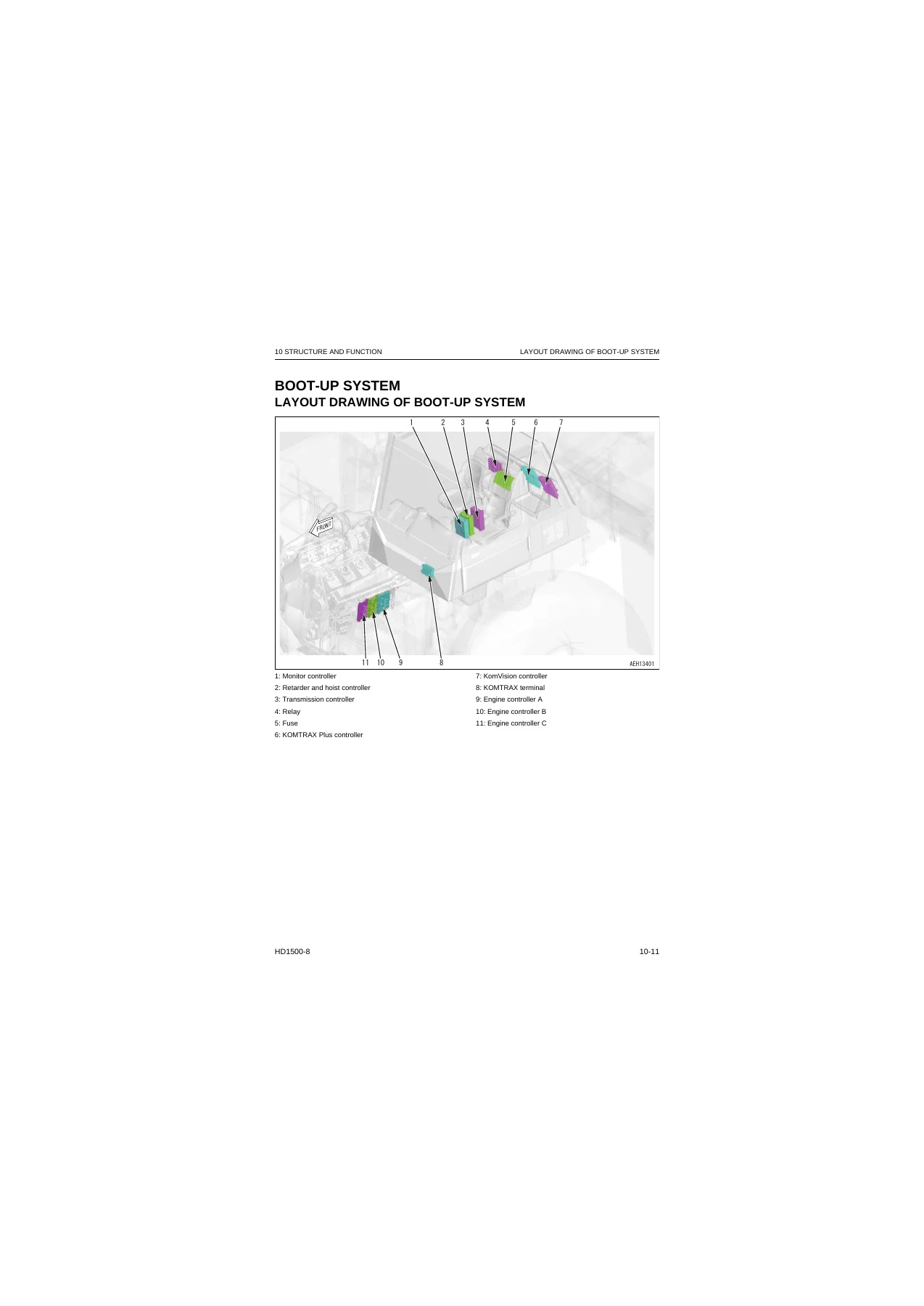
- 10 STRUCTURE AND FUNCTION — Boot-up system, engine system, cooling system, control system, hydraulic system, power train system, work equipment system, steering system, brake system, undercarriage and frame, cab and attachments
- 20 STANDARD VALUE TABLE — Standard value table for engine and machine, machine posture and procedure for measuring performance
- 30 TEST AND ADJUST — Engine and cooling system, power train, steering system, brake system, hydraulic system, work equipment, cab and attachments, electrical system, machine monitor setting and operation, KOMTRAX settings, Pm clinic
- 40 TROUBLESHOOTING — Failure codes table, troubleshooting by failure code, electrical system (E-mode), hydraulic and mechanical systems (H-mode), connectors list and layout, fuse location table, T-branch box and adapter tables
- 50 DISASSEMBLY AND ASSEMBLY — Engine and cooling system, power train, brake system, steering system, undercarriage and frame, hydraulic system, work equipment, cab and attachments, electrical system
- 60 MAINTENANCE STANDARD — Engine and cooling system, power train, steering system, brake system, undercarriage and frame, hydraulic system, work equipment, cab and attachments
- 80 THE OTHER INFORMATION — Air conditioner system, KomVision system
- 90 CIRCUIT DIAGRAMS — Hydraulic circuit diagrams and electrical circuit diagrams
The scope of this workshop manual is unusually broad. It covers the SDA16V159-3 engine, the torque flow transmission with seven forward and one reverse speeds, the torque converter with lockup clutch, the full hydraulic system for steering and hoist control, the oil-cooled multiple-disc brakes with retarder and parking brake functions, the hydropneumatic suspension, and the complete electrical/electronic control architecture including the machine monitor, KOMTRAX Plus, and KomVision systems. Within the troubleshooting chapter, failure codes are individually indexed — from transmission clutch failures to sensor circuit faults — with step-by-step diagnostic procedures, connector pin assignments, and resistance/voltage criteria. The disassembly and assembly chapter details removal, installation, and overhaul procedures for the engine, transmission, torque converter, differential, final drive, brakes, suspension cylinders, hoist cylinder, steering cylinder, and hydraulic valves, with tightening torques and coating material specifications.
What This Manual Enables
With this Komatsu HD1500-8 shop manual, a technician can perform the full range of service work on the machine. That includes:
- Reading and clearing failure codes from the machine monitor, and tracing each code to its root cause
- Testing engine speed, blowby pressure, fuel pressure, and exhaust gas color to evaluate engine condition
- Measuring power train oil pressures at the main relief valve, torque converter inlet and outlet, and each clutch circuit
- Diagnosing and repairing the transmission control system, including ECMV solenoid circuits, fill switches, and speed sensors
- Servicing the brake system: accumulator charge pressure, brake valve, slack adjusters, retarder control, and parking brake release
- Overhauling the engine, torque converter, transmission, differential, final drive, and wheel brakes with proper tolerances and torque values
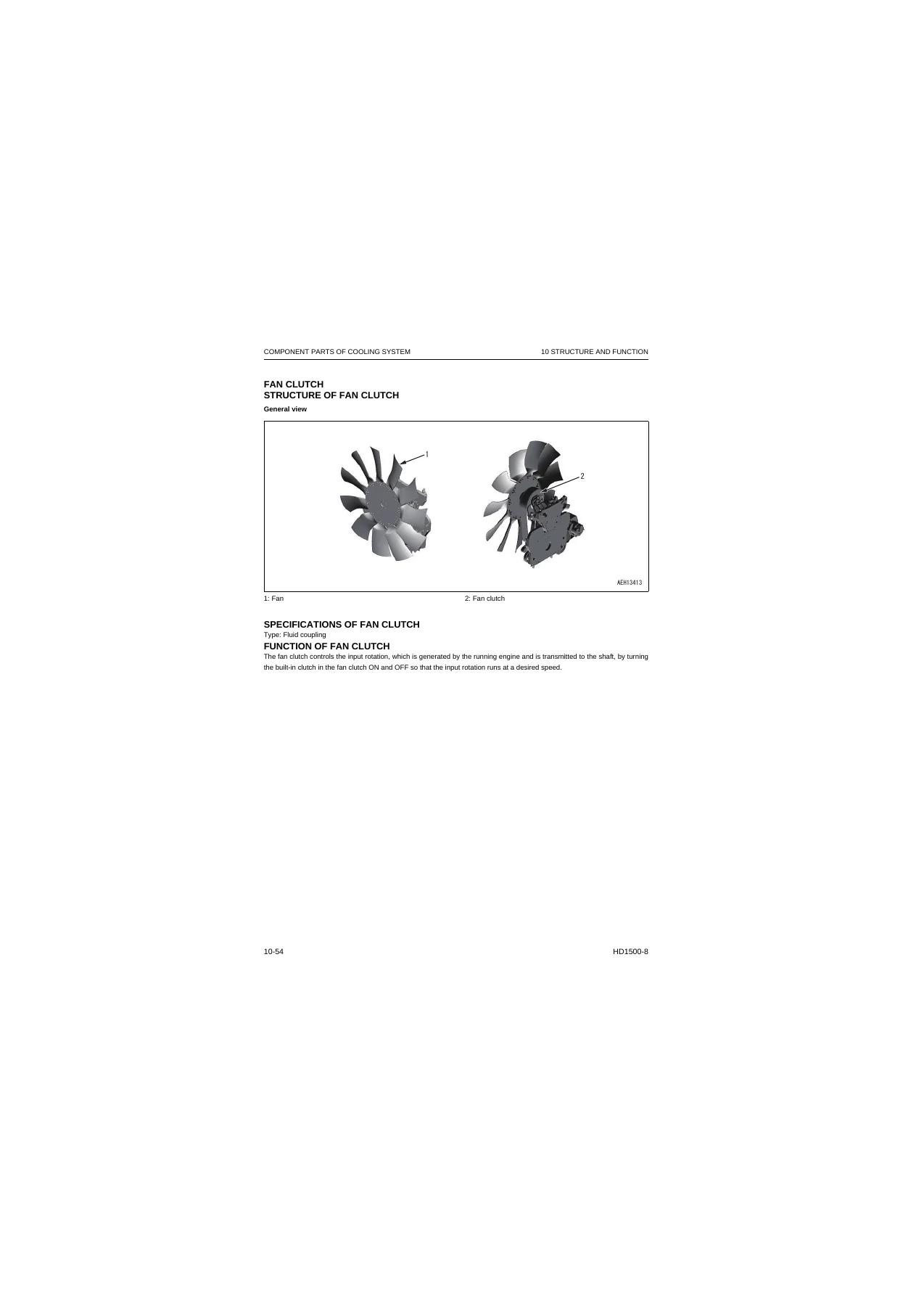
- Testing and adjusting the steering circuit, hoist circuit, suspension cylinders, and fan clutch
- Using the machine monitor service mode for monitoring, abnormality records, maintenance settings, payload meter configuration, and KOMTRAX settings
- Performing the Pm clinic inspection and quick Pm data collection
- Navigating the electrical circuit diagrams and hydraulic circuit diagrams to trace wiring and piping
What distinguishes a shop manual from a general repair guide is the precision of the information. This manual provides the standard values, repair limits, tightening torques, and adjustment criteria that factory-trained technicians use. Without those exact specifications, a repair can end up out of tolerance — leading to premature failure, poor performance, or unsafe operating conditions. The testing and adjusting chapter tells you not just what to measure but how to set up the test, what conditions the machine must be in, and what the acceptable range is. The troubleshooting chapter narrows down a fault systematically instead of leaving you to guess which component is at fault.
Who This Manual Is For
This shop manual is written for professional diesel technicians, fleet maintenance managers, and heavy equipment mechanics who service Komatsu HD1500-8 mining dump trucks. It assumes familiarity with diesel engines, powershift transmissions, hydraulic systems, and electrical diagnostics. The procedures are detailed enough for a technician to disassemble and reassemble major components, test circuits, and interpret failure codes without needing the factory software. It is also a valuable reference for equipment owners who want to understand the machine’s systems, plan maintenance, or verify that a repair is being done correctly.
The manual covers the HD1500-8 with the SDA16V159-3 engine, serial numbers 81001 and up. It is not a generic guide — it is specific to this model and engine combination, with serial-number-specific information where applicable.
Why the Right Specifications Matter
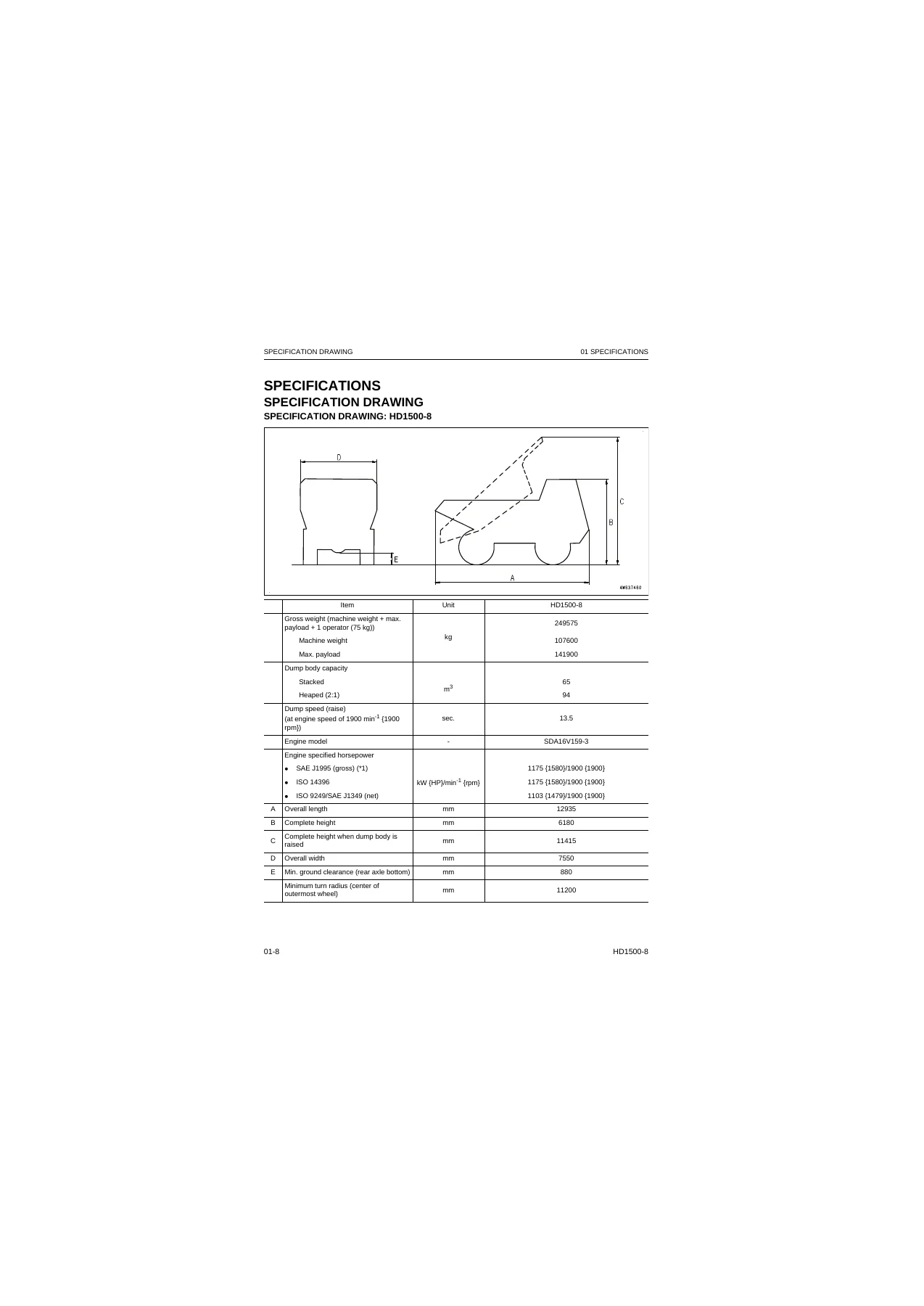
On a machine of this size — the HD1500-8 has a gross weight of nearly 250 tonnes and a payload capacity of almost 142 tonnes — incorrect repair procedures carry serious consequences. A transmission clutch pack assembled with the wrong clearance can slip and burn out under load. A brake circuit not bled properly can fail to stop the machine on a grade. An engine assembled with incorrect bearing clearances can seize. The factory specifications in this manual exist to prevent those outcomes.
Consider just the oil pressure values. The power train main relief pressure is 4.09 MPa ± 0.20 MPa at 1900 rpm. The torque converter inlet pressure is 1.15 MPa ± 0.10 MPa. The lockup clutch operating pressure is 2.01 MPa ± 0.20 MPa. Each clutch circuit has its own specified operating pressure — L clutch at 1.91 MPa, H clutch at 1.67 MPa, 1st and 2nd clutches at 3.43 MPa, 3rd at 1.91 MPa, 4th at 1.86 MPa, and R clutch at 3.53 MPa. These are not arbitrary numbers; they are the pressures at which the transmission shifts correctly, holds under load, and wears evenly. Having the values and the test procedures to verify them is what allows a technician to diagnose a transmission problem accurately rather than replacing parts by guesswork.
The same principle applies throughout the manual. The brake accumulator cut-in pressure is 11.76 MPa, cut-out is 20.6 MPa. The steering circuit relief pressure is 24.0 ± 0.98 MPa. The hoist circuit relief pressure is 24.0 MPa for the steering and hoist pump and 25.4 ± 1 MPa for the hoist and front brake cooling remote motor drive pump. Each value corresponds to a specific test procedure with defined conditions — oil temperature ranges, engine speeds, and control lever positions — so the measurement is repeatable and meaningful.
IMAGES PREVIEW
Instant PDF Delivery
This Komatsu HD1500-8 shop manual is delivered as a PDF file that you can download immediately after purchase. There is no shipping, no waiting for a physical book, and no restriction on how many times you access the file. You can view it on a laptop, tablet, or smartphone, and print any page or section you need for the workshop floor. The PDF format preserves the original layout, including all diagrams, tables, and exploded views, so the information is presented exactly as it appears in the factory manual.
Whether you are performing routine maintenance, diagnosing a fault code, or overhauling a major component, this manual gives you the specifications and procedures to do the job correctly. Keep it on hand as a reference and you have the technical information for the HD1500-8 at your fingertips.
Reviews
There are no reviews yet.