
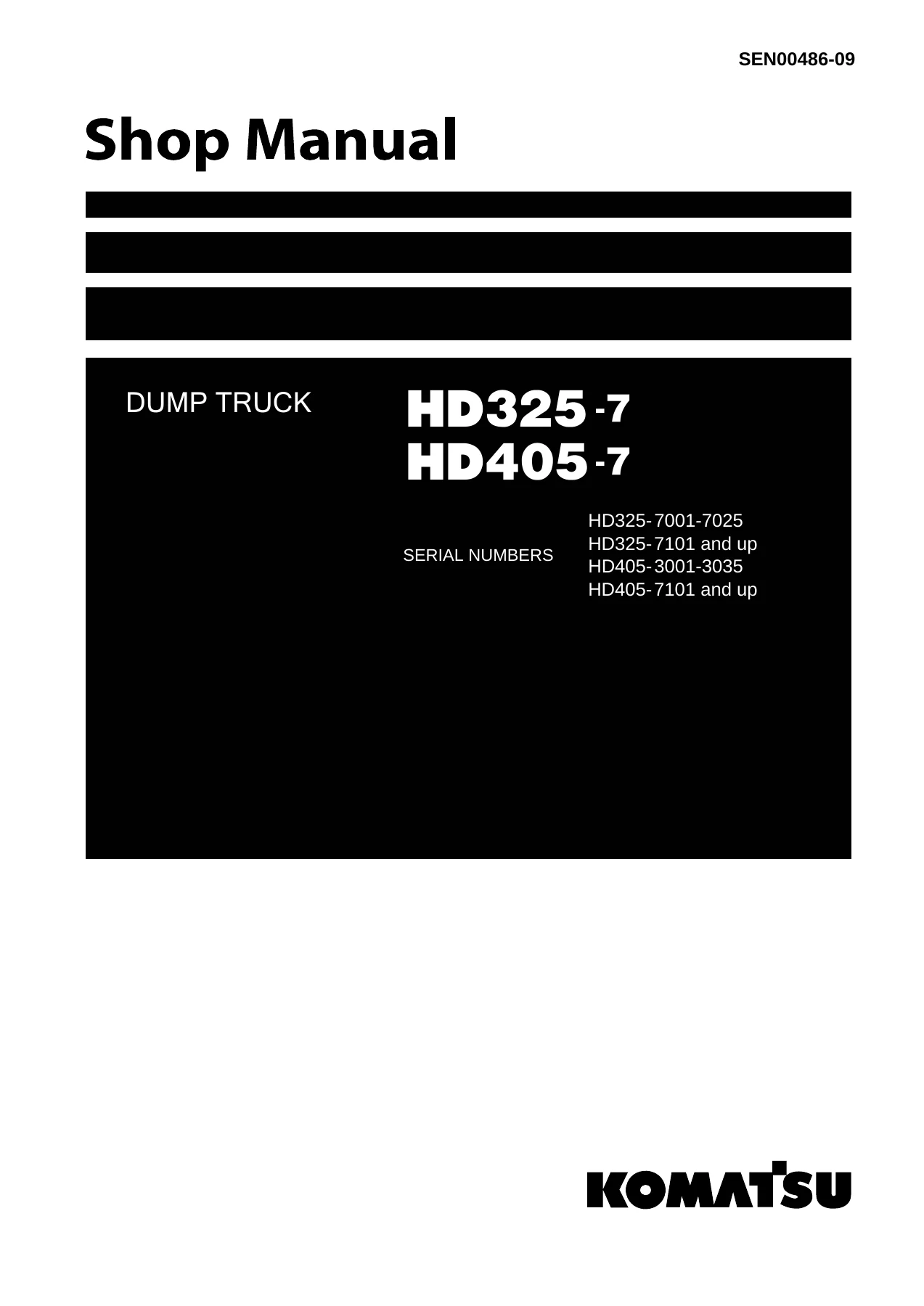
Komatsu HD325-7 & HD405-7 Dump Truck Shop Manual SEN00486-09 – Complete PDF Service & Repair Guide
Original price was: $69.95.$49.95Current price is: $49.95.
The complete Komatsu HD325-7 and HD405-7 dump truck shop manual (SEN00486-09) in a single PDF. Over 1,300 pages covering engine, power train, brakes, hydraulics, electrical systems, troubleshooting, testing and adjusting, disassembly and assembly, plus full hydraulic and electrical diagrams.
Description
Komatsu HD325-7 & HD405-7 Dump Truck Shop Manual – SEN00486-09
This is the complete Komatsu HD325-7 and HD405-7 dump truck shop manual, form number SEN00486-09, published by Komatsu in 2009. It is a single PDF containing every section of the original manual — the same technical content used by Komatsu service technicians to maintain, diagnose, repair and overhaul these machines.
Whether you are servicing a HD325-7 from serial 7001–7025 or 7101 and up, or an HD405-7 from serial 3001–3035 or 7101 and up, this manual covers the complete machine. It includes the KOMATSU SAA6D140E-5 engine, TORQFLOW transmission, torque converter, differential, final drive, steering, brakes, suspension, hydraulic system, electrical system, and all associated testing, adjusting, troubleshooting and disassembly procedures.
File Details
- Manual type: Shop Manual
- Brand / Manufacturer: Komatsu
- Models covered: HD325-7, HD405-7
- Serial numbers: HD325-7: 7001–7025, 7101 and up · HD405-7: 3001–3035, 7101 and up
- Document number: SEN00486-09
- Publication date: June 2009
- Language: English
- File format: PDF
- Page count: Approximately 1,394 pages
Chapters Covered
The manual is divided into the following top-level sections, each containing the full original technical content:
- 00 Index and foreword
- 01 Specification
- 10 Structure, function and maintenance standard
- 20 Standard value table
- 30 Testing and adjusting
- 40 Troubleshooting
- 50 Disassembly and assembly
- 90 Diagrams and drawings
01 Specification
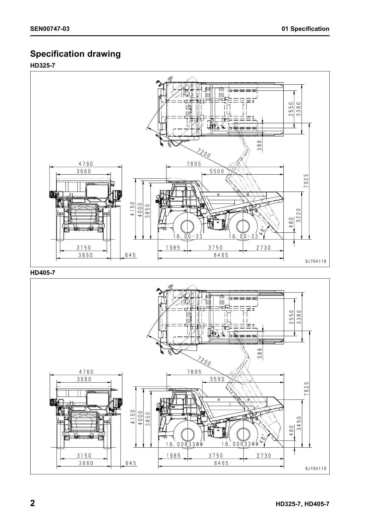
This section provides the specification drawing and full technical data for both the HD325-7 and HD405-7. It includes the specification drawing with overall dimensions, a comprehensive specifications table covering engine, power train, suspension, tires, brake system, hydraulic system and cylinders, a weight table listing component weights, and a fuel, coolant and lubricants chart. This is the starting point for anyone needing to confirm capacities, dimensions or standard machine data.
10 Structure, Function and Maintenance Standard
This is the largest section of the manual, covering the structure, function and maintenance standards for every major system on the truck. It begins with the engine and cooling system, covering the radiator, oil cooler, aftercooler and output shaft, with detailed specifications and maintenance criteria.
The power train section is divided into two parts. Part 1 covers the power train skeleton, drive shaft, torque converter and transmission hydraulic piping, power train charge pump, retarder cooling pump, torque converter, torque converter valve, transmission, transmission control valve and ECMV. Part 2 covers the axle, differential, final drive and wheel. The transmission section alone includes the full planetary gear system, clutch combinations for all seven forward speeds and reverse, and complete disassembly and assembly data.
The steering system section covers the steering column, steering linkage and related components. The brake system section is extensive, covering brake piping, brake valve, secondary brake valve, relay valve, front brake cut valve, accumulator charge valve, slack adjuster, brake, proportional reducing valve, parking brake, parking brake solenoid and hand brake (retarder).
The undercarriage and frame section covers the suspension, suspension cylinder and rear axle support. The hydraulic system section includes the steering and hoist oil pressure piping diagram, dump body control, hydraulic tank, steering valve, cross-over relief valve, steering control valve, hoist valve, dump control valve (EPC valve), steering cylinder, hoist cylinder, and the work equipment and steering pump.
The cab and its attachments section covers the ROPS cab, air conditioner and rear view monitor. The electrical system is divided into four parts: machine monitor system; automatic shift control system, transmission controller, auto emergency steering system, retarder control system, battery disconnector switch, dump control lever and auto suspension system; payload meter II (card type); and sensors, switches and KOMTRAX terminal system.
20 Standard Value Table
This section provides the standard service value table for the engine and for the machine. It lists the standard values for new machines and the service limit values used when testing, adjusting and troubleshooting. This includes engine speeds, intake and exhaust pressures, compression pressure, blow-by pressure, engine oil pressure, torque converter stall speed, transmission clutch pressures, brake pressures, hydraulic pressures, suspension cylinder pressures and much more.
30 Testing and Adjusting
This section is split into four parts and covers all testing and adjusting procedures with the required tools, measurement conditions, standard values and adjustment methods. Part 1 covers engine and cooling system testing: engine speed, intake air pressure, exhaust temperature, exhaust gas color, valve clearance, compression pressure, blow-by pressure, engine oil pressure, EGR valve and bypass valve drive oil pressure, fuel system handling, fuel pressure, fuel return rate, air bleeding, fuel circuit leakage, and belt tension for alternator, fan and air conditioner compressor. Part 2 covers power train and brake testing: torque converter stall speed, power train oil pressure, transmission speed sensor adjustment, brake oil pressure, accumulator nitrogen gas pressure and charging, brake performance, parking brake adjustment, brake circuit air bleeding, brake wear inspection, emergency parking brake release, suspension cylinder testing and adjustment, steering and hoist circuit hydraulic pressure, dump EPC circuit oil pressure, steering cylinder air bleeding, emergency body raising, body positioner sensor adjustment, engine controller high voltage circuit handling, transmission controller adjustment and emergency escape at electrical system failure. Part 3 covers setting and adjusting of devices and special functions of the machine monitor (EMMS). Part 4 covers KOMTRAX terminal operation, lamp display, Pm Clinic check sheet, and card-type payload meter setting.
40 Troubleshooting
The troubleshooting section is one of the most valuable parts of this manual. It begins with general information on troubleshooting, including points to remember, sequence of events, checks before troubleshooting, classification and procedures, connector pin number connection tables, and T-branch box and adapter tables.
The failure code troubleshooting is divided into five parts. Part 1 covers transmission and power train failure codes including dual engagement, transmission oil filter clogging, R to F shifting abuse, clutch disk abuse, clutch slipping, clutch solenoid fill signal and malfunction codes, lockup clutch solenoid, engine over run prevention, parking brake, accumulator oil pressure, engine oil filter clogging, air cleaner clogging, alternator malfunction, engine oil pressure, coolant level, engine overheat, brake oil overheat, torque converter oil overheat, battery electrolyte level, and steering oil overheat.
Part 2 covers engine controller failure codes including engine controller abnormality, engine Ne and Bkup sensors, charge pressure sensor, throttle sensor, oil pressure sensor, coolant temperature sensor, charge temperature sensor, sensor power sources, atmospheric pressure sensor, engine over speed, engine Ne speed sensor power source, fuel temperature sensor, PCV1 and PCV2 circuits, injector circuits for all six cylinders, engine controller data consistency, injector drive circuit, idle validation switch, power source voltage, common rail pressure, common rail pressure sensor, supply pump pressure feed, engine Ne speed sensor, engine Bkup speed sensor phase, loss of engine controller data, engine Bkup speed sensor, EGR valve servo, bypass valve solenoid drive, bypass valve servo, and more.
Part 3 covers bypass valve lift sensor, KOMNET, EGR inlet pressure sensor, throttle sensor power source, supply pump pressure feed, EGR valve lift sensor, EGR valve solenoid drive, intake air heater relay, stop lamp relay, front brake cut-off solenoid valve, connector connection, CAN communication, transmission controller power supply and memory, model selection, communication lost, retarder controller, ABS controller, ARSC and ASR system switches, clutch fill switches, gear shift lever, transmission oil temperature sensor, retarder oil temperature sensor, steering oil temperature sensor, and torque converter oil temperature sensor.
Part 4 covers suspension pressure sensors, torque converter oil pressure sensor, accumulator oil pressure sensors, fuel level sensor, steering angle potentiometer, retarder lever potentiometer, hoist lever potentiometers, body positioner sensor, steering speed sensor, pitch angle sensor, transmission input, intermediate and output shaft speed sensors, wheel speed sensors, buzzer output, auto suspension solenoids, kick-out solenoid, hoist select valve, rear brake BCV command, ASR shut-off valve, rear brake proportional pressure reducing solenoid valve, and hoist EPC valve output circuits.
Part 5 covers ASR proportional pressure reducing solenoid valves (right and left), lockup clutch solenoid output circuits, Hi clutch solenoid output circuits, Lo clutch solenoid output circuits, 1st clutch solenoid output circuits, 2nd clutch solenoid output circuits, 3rd clutch solenoid output circuits, R clutch solenoid output circuits, and 4th clutch solenoid output circuits.
There is also troubleshooting of the electrical system (E-mode) covering engine does not start, automatic preheating, machine monitor display, alarm buzzer, gauges and caution lamps, character display selection, power mode selection, AISS function, seat belt caution lamp, turn signal and hazard lamps, night illumination, and emergency steering. Troubleshooting of the hydraulic and mechanical system (H-mode) covers machine does not start, machine does not travel smoothly, lockup cannot be cancelled, excessive shock when starting or shifting, transmission does not shift up, machine lacks power or speed, time lag when starting or shifting, torque converter oil temperature and pressure, front and rear brake ineffectiveness, steering wheel heavy or not working or vibrating, dump body lifting speed slow, dump body does not work, and excessive hydraulic drift of dump body. Troubleshooting of the mechanical system (S-mode) covers starting performance, engine does not start, engine does not pick up smoothly, engine stops during operations, engine does not rotate smoothly, engine lacks output, exhaust gas color, oil consumption, oil contamination, fuel consumption, oil in coolant, oil pressure drops, oil level rises, coolant temperature too high, abnormal noise, and vibration.
50 Disassembly and Assembly
This section provides the complete disassembly and assembly procedures for every major assembly on the truck. It begins with general information on disassembly and assembly, including how to read the manual, a coating materials list, special tool list and sketches of special tools. It then covers engine and cooling system (engine assembly, radiator assembly, output shaft assembly, fuel supply pump assembly, cylinder head assembly, fuel injector assembly, engine front seal and engine rear seal), power train Part 1 (torque converter and transmission assembly, torque converter and control valve assembly, torque converter assembly, PTO assembly, transmission assembly, transmission control valve assembly and ECMV assembly), power train Part 2 (differential assembly, rear final drive carrier assembly, rear final drive assembly and front wheel hub assembly), steering system (steering cylinder assembly and emergency steering motor pump assembly), brake system (front brake caliper pad and assembly, rear brake assembly, parking brake pad and caliper assembly, front brake caliper pad assembly, parking brake spring cylinder assembly, slack adjuster assembly), undercarriage and frame (front and rear wheel assemblies, front and rear suspension cylinder assemblies, variable damping selector valve assembly), hydraulic system (hoist cylinder assembly), body assembly, cab and its attachments (operator’s seat assembly and air conditioner unit assembly), and electrical system (engine controller assembly, transmission controller assembly and retarder controller assembly).
90 Diagrams and Drawings
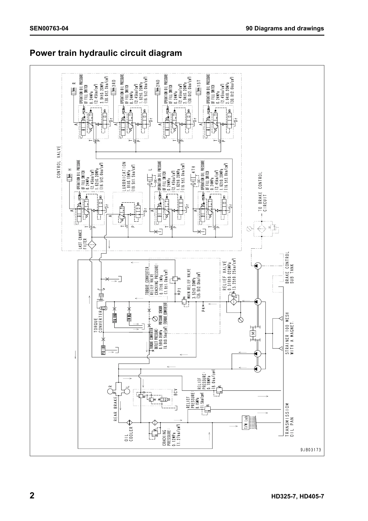
This section contains the hydraulic diagrams and drawings, including the power train hydraulic circuit diagram, steering and hoist hydraulic circuit diagram (with separate versions for different serial number ranges), and brake hydraulic circuit diagram. It also contains the electrical diagrams and drawings, including the electrical circuit diagram for inside cab (five parts with separate versions for different serial number ranges), electrical circuit diagram for outside cab (three parts), air conditioner electrical circuit diagram, and connectors table and arrangement drawing. These diagrams are essential for tracing circuits, understanding hydraulic flow paths and diagnosing electrical faults.
Why This Komatsu Shop Manual Matters
The Komatsu HD325-7 and HD405-7 are heavy-duty off-highway dump trucks designed for demanding mining, quarry and construction applications. When a machine goes down, every hour of downtime costs money. Having the correct service information on hand means the difference between a quick, correct repair and a prolonged, expensive guessing game.
This manual gives you the complete structure and function of every major system, the exact standard values and service limits, the full testing and adjusting procedures, the troubleshooting logic to pinpoint faults, and the disassembly and assembly steps to carry out repairs correctly. It covers the engine and cooling system, torque converter and transmission, differential and final drive, steering, brakes, suspension, hydraulic system, electrical system, machine monitor, payload meter and KOMTRAX terminal.
For anyone responsible for maintaining, repairing or overhauling a HD325-7 or HD405-7, this manual is the definitive technical reference. It is not a generic guide or a selection of extracts — it is the complete shop manual in a single PDF.
IMAGES PREVIEW
Instant PDF Delivery – No Shipping, No Waiting
This Komatsu HD325-7 HD405-7 shop manual is delivered as an instant PDF download. There is no physical book to ship, no waiting for delivery, and no risk of a damaged or lost parcel. As soon as your order is complete, you can download the manual and start using it immediately.
The PDF can be viewed on any device — desktop computer, laptop, tablet or smartphone — and you can print the pages you need for the workshop. Whether you are working in the field, in the service bay or at the office, the manual is always accessible. Keep it on your device for quick reference, or print the sections you use most and keep them with the machine.
With over 1,300 pages of technical content, this is the most comprehensive single resource available for the Komatsu HD325-7 and HD405-7. It covers everything from routine maintenance and adjustment to complete overhaul and troubleshooting of the engine, transmission, hydraulics and electrical systems. If you own, operate, maintain or repair these machines, this manual belongs in your library.
Reviews
There are no reviews yet.