
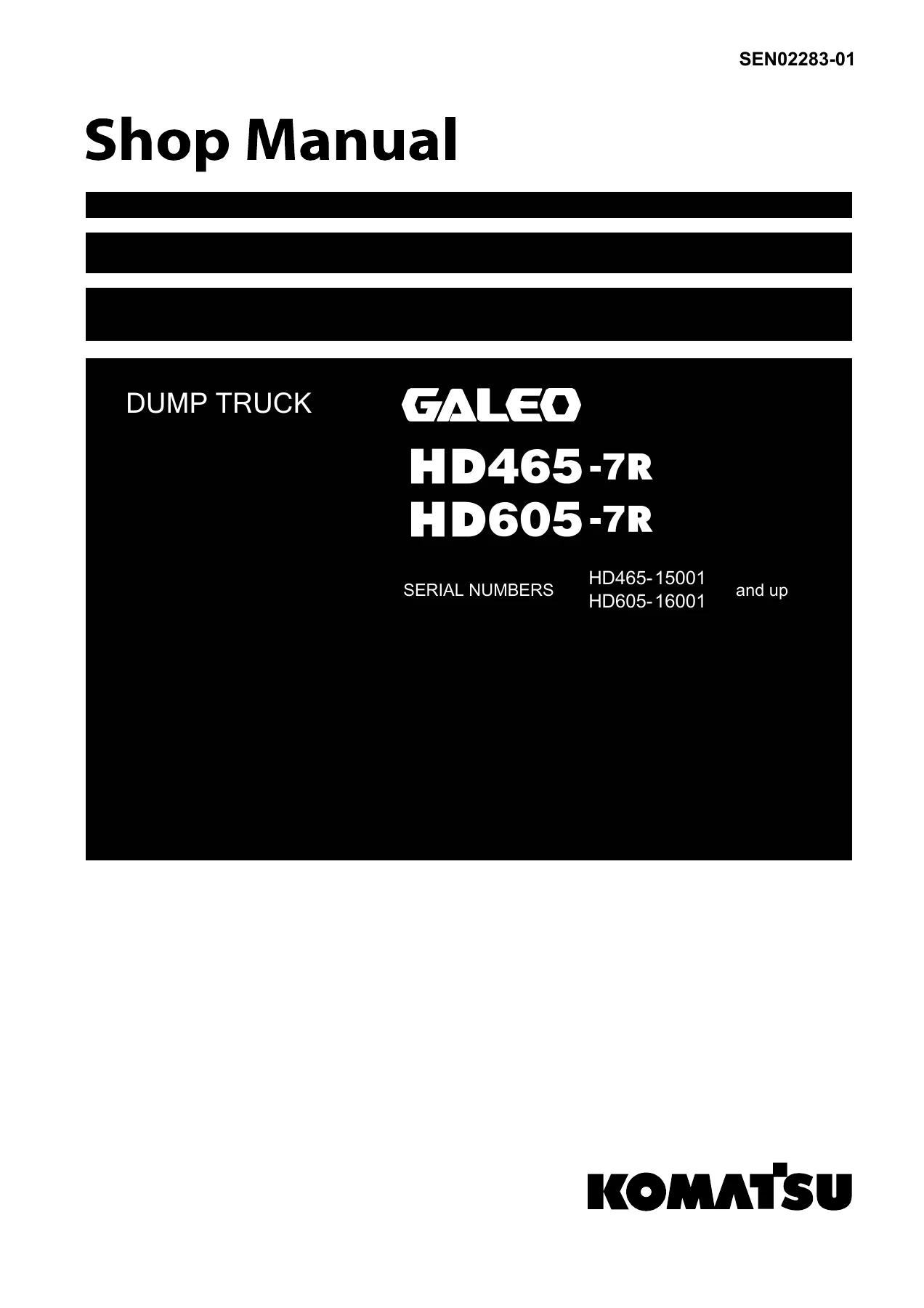
Komatsu HD465-7R HD605-7R Dump Truck Shop Manual – Complete Workshop PDF
Original price was: $49.95.$29.95Current price is: $29.95.
Full Komatsu shop manual for the GALEO HD465-7R and HD605-7R dump trucks (S/N HD465-15001 and up, HD605-16001 and up). Covers specification, structure and function, standard values, testing and adjusting, troubleshooting, and hydraulic/electrical circuit diagrams across roughly 1,225 pages.
Description
Komatsu HD465-7R & HD605-7R Dump Truck Shop Manual
This is the complete Komatsu shop manual covering the GALEO HD465-7R and HD605-7R dump trucks. It is the multi-volume workshop reference Komatsu service personnel use for specification data, component structure and function, standard values, testing and adjusting procedures, failure-code driven troubleshooting, and circuit diagrams. The manual applies to HD465-7R units from serial number 15001 and up, and HD605-7R units from serial number 16001 and up.
The Komatsu HD465-7R HD605-7R Dump Truck Shop Manual is written for technicians who need factory-level detail on the SAA6D170E-5 engine, TORQFLOW transmission, torque converter with lockup clutch, rear axle, brakes, suspension, steering and hoist hydraulics, and the machine monitor network that ties the controllers together. Everything is presented in English with metric and imperial unit pairs, so workshop staff can work directly from the text without converting values.
File Details
- Manual type: Shop Manual (workshop service manual set)
- Brand: Komatsu
- Models covered: HD465-7R, HD605-7R (GALEO)
- Serial ranges: HD465-15001 and up, HD605-16001 and up
- Language: English
- Page count: Approximately 1,225 pages
- File format: PDF
- Form numbers: SEN02283-01 (binder), SEN02284-01 through SEN02314-01 (individual sections)
- Publication data: Komatsu, printed in Japan, 11-06 (02) / 01-07 (02)
Chapters Covered
The manual is assembled from numbered sections, each with its own form number. The structure follows Komatsu’s standard shop manual layout:
- 00 Index and Foreword – index, composition list, safety notice, how to read the manual, maintenance standard terms, handling of electrical and hydraulic components, wiring code reading, general operation precautions, push-pull coupler disconnection, standard tightening torque tables, conversion tables
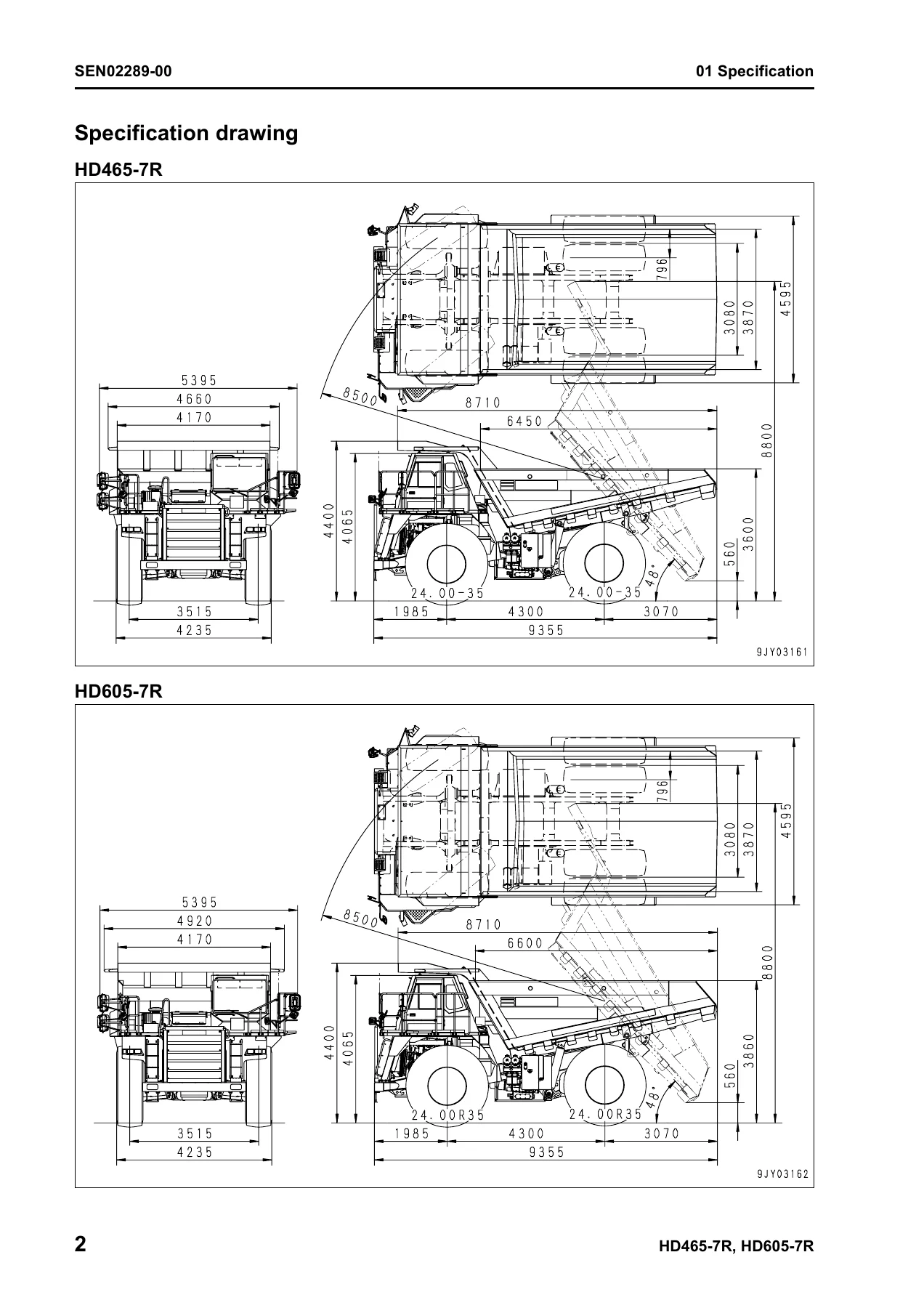
- 01 Specification – specification drawings, machine specifications, weight table, fuel/coolant/lubricant recommendations and capacities
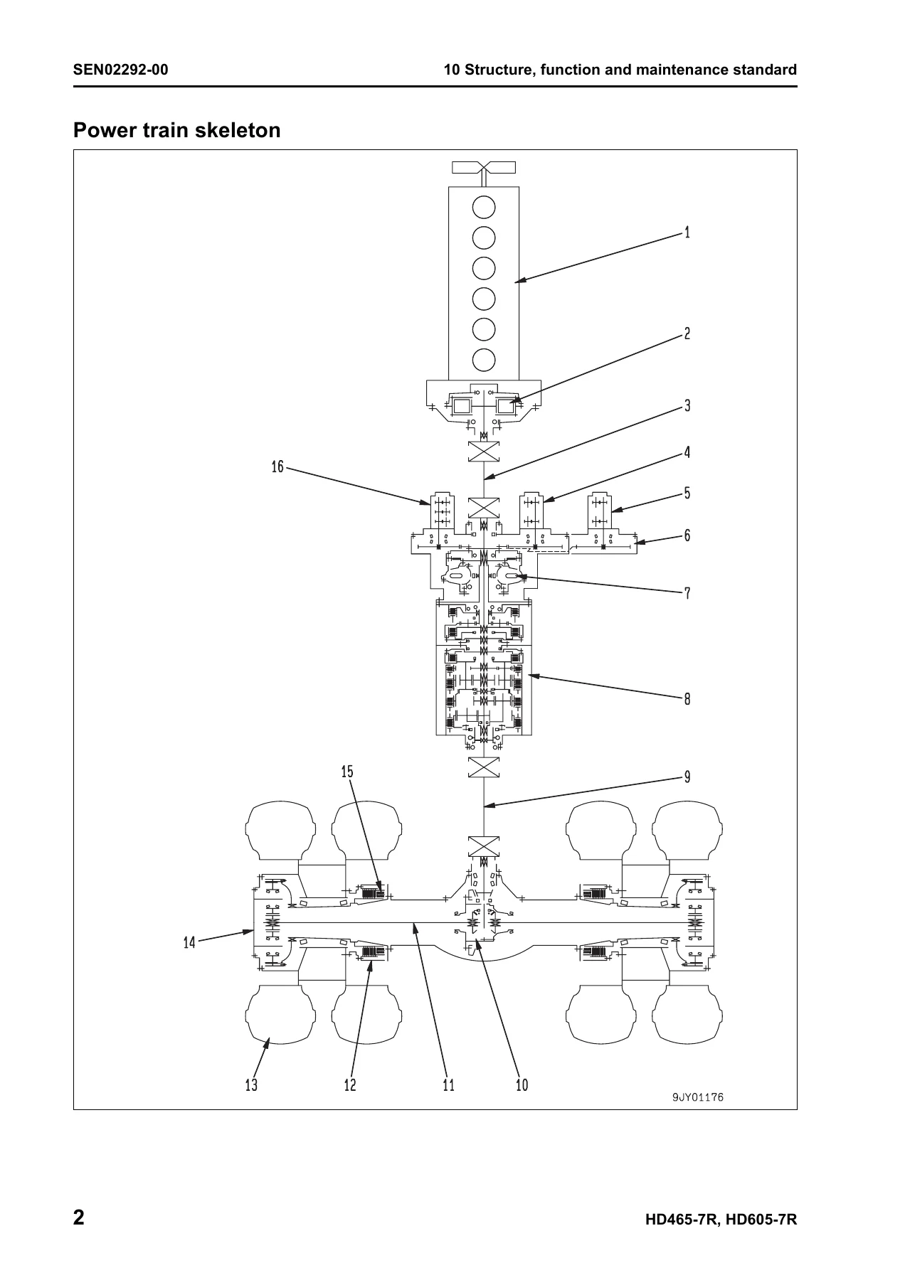
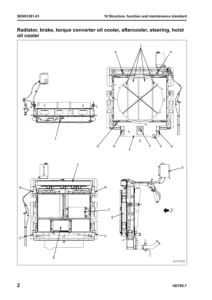
- 10 Structure, Function and Maintenance Standard – engine and cooling system (radiator, torque converter oil cooler, aftercooler, work equipment oil cooler, fuel system, brake oil cooler, output shaft); power train system part 1 (power train skeleton, drive shaft, torque converter and transmission hydraulic piping, brake cooling oil control valve, torque converter, torque converter valve, transmission, transmission control valve, ECMV); power train system part 2 (axle, differential, final drive, wheels); steering system (steering column, steering linkage); brake system (brake piping, brake valve, secondary brake valve, relay valve, front brake off valve, accumulator charge valve, accumulator, slack adjuster, brake, parking brake solenoid valve); undercarriage and frame (suspension, suspension cylinder, rear axle support); hydraulic system (steering and hoist piping, dump body control, hydraulic tank, steering valve, crossover relief valve, steering cylinder, steering control valve, hoist valve, EPC valve, hoist cylinder, hydraulic pump); cab and its attachments (air conditioner); electrical system parts 1–4 (machine monitor, automatic shift control, transmission controller, emergency steering, auto suspension, retarder control, payload meter, VHMS controller, sensors and switches)
- 20 Standard Value Table – engine standard values, steering and hoist hydraulic circuit values, machine standard values
- 30 Testing and Adjusting – testing tools, engine speed, boost pressure, exhaust temperature and gas colour, valve clearance, compression pressure, blow-by, engine oil pressure, fuel system pressure, cylinder cut-out and no-injection cranking, torque converter stall speed, power train and brake oil pressure, transmission speed sensor, accumulator gas charge, brake performance and wear, suspension cylinder adjustment, steering/hoist and dump EPC circuit pressure, body positioner sensor, transmission controller adjustment, emergency escape procedures, and monitor service functions (EMMS)
- 40 Troubleshooting – failure code table and fuse locations, general troubleshooting procedure, troubleshooting by failure code (Parts 1–9), troubleshooting of electrical system (E-mode), hydraulic and mechanical system (H-mode), and engine (S-mode)
- 90 Diagrams and Drawings – power train hydraulic circuit diagram, steering and hoist hydraulic circuit diagram, brake hydraulic circuit diagram, electrical circuit diagrams for inside and outside the cab, connector table and arrangement drawings
Reading through the Komatsu HD465-7R HD605-7R dump truck shop manual as a whole gives a technician a complete lifecycle reference for the machine: the specification chapter establishes what the truck is, the structure and function chapters explain how each system is built and how it behaves, the standard value table establishes the pass/fail criteria, the testing and adjusting chapter tells you how to measure and correct it, the troubleshooting chapter tells you what to do when it misbehaves, and the diagrams chapter gives you the circuit-level view of the hydraulic and electrical systems.
Coverage for Both Truck Sizes
The two trucks share the shop manual but differ in payload class, weight distribution, and body capacity, so the specification and weight tables list both machines side by side. The HD465-7R is the smaller of the pair, and the HD605-7R carries more load. Both are powered by the Komatsu SAA6D170E-5, a 4-cycle, water-cooled, in-line six-cylinder direct injection diesel with turbocharger and aftercooler. The service chapters apply to either machine unless a heading or table states otherwise, and the serial-number scope (HD465-15001 and up, HD605-16001 and up) is printed on the cover of the manual.
Diagnostic and Circuit Detail
The failure-code sections in this shop manual are unusually granular. There are dedicated pages for clutch-system faults on individual transmission clutches, solenoid and fill-switch faults, accumulator oil pressure loss, engine controller and common rail codes, sensor disconnection and short-circuit faults, CAN communication faults across the machine monitor, transmission, retarder, engine, ABS and VHMS controllers, and output-circuit faults for the hoist EPC valve, the rear brake proportional valve, the ASR valves and the auto-suspension solenoids. Each code entry lists the contents of the trouble, the action the controller takes, the symptom the operator sees, and a cause-by-cause diagnostic route with resistance and voltage checks.
Alongside the failure codes, the E-mode, H-mode and S-mode sections cover symptoms that the machine cannot detect by itself – for example steering that is heavy, brakes that are ineffective, a hoist body that will not lift, or an engine that lacks power – each mapped back to a set of possible causes with the standard values required to judge them.
The diagrams section is the other half of the diagnostic toolkit. Hydraulic circuit diagrams cover the power train, steering and hoist, and brake circuits, and the electrical circuit diagrams are split between inside and outside the cab, with a connector table and arrangement drawing so a technician can trace a signal to the correct pin on the correct connector.
What You Can Do With This Manual
With the Komatsu HD465-7R HD605-7R Dump Truck Shop Manual on hand, a workshop can:
- Look up specification data and weights for either truck, and cross-check fuel, coolant, and lubricant requirements against the ambient temperature range
- Understand the structure and operating principle of the torque converter, transmission, brake cooling oil control valve, accumulator charge valve, slack adjuster, hoist valve, EPC valve, and the steering control valve before touching them
- Judge wear and clearance against the standard value table, including clutch disc and plate thicknesses, seal ring wear limits, spring free and installed lengths, backlashes, and cylinder and bushing clearances
- Carry out engine tests (speed, boost pressure, exhaust temperature and colour, valve clearance, compression pressure, blow-by, oil pressure, fuel pressure and return rate) and power train and brake tests (torque converter stall, main relief, clutch pressures, brake pressures, accumulator nitrogen pressure and brake performance)
- Perform the machine monitor service functions – real-time monitoring, reduced cylinder mode, no-injection cranking, transmission ECMV tuning, transmission initial learning, maintenance monitor settings, option selection and model selection
- Work through failure codes systematically, using the reference to the specific part 1–9 troubleshooting section instead of guessing at a fault
- Trace hydraulic and electrical circuits from the diagrams, including the CAN network that links the machine monitor with the transmission, engine, retarder, ABS and VHMS controllers
- Set up, initialize or replace the VHMS controller, the payload meter, and the card-type payload meter, using the dedicated testing and adjusting procedures
Why the Correct Procedures and Values Matter
The HD465-7R and HD605-7R are high-payload haul trucks. A clutch pressure that is out of tolerance, a drag in the parking brake, or an accumulator that has lost nitrogen charge will shorten component life or compromise braking and steering, and the cost of that is measured in downtime. The standard values printed in this shop manual – main relief pressures, torque converter inlet and outlet pressures, individual clutch set pressures, accumulator charge pressures, relief valve settings, and clearance limits – are the reference a technician needs to confirm a repair is correct rather than simply reassembled. The test procedures in the testing and adjusting sections specify the oil temperature and engine speed conditions that make a reading meaningful, and the failure-code sections tell you what the controller already knows before you start.
Because the manual is written for both trucks and covers all sub-assemblies from the engine output shaft through to the wheels, it also removes the need to chase separate documents for individual systems. Everything required to understand, test, diagnose, and adjust the truck is in one place, in English, with metric and imperial units side by side.
IMAGES PREVIEW
Instant PDF Delivery
This Komatsu HD465-7R HD605-7R dump truck shop manual is delivered as an instant PDF download. There is no physical shipment, no waiting for a courier, and no risk of a lost binder. Once payment is complete, the file is available to download and can be opened on a workshop laptop, a desktop PC, a tablet, or a phone, so the relevant section can be pulled up on the shop floor while the machine is being worked on. Any page, table, or diagram can be printed for use as a bench reference during a repair, and the file can be kept on file for as long as the truck is in service.
Reviews
There are no reviews yet.