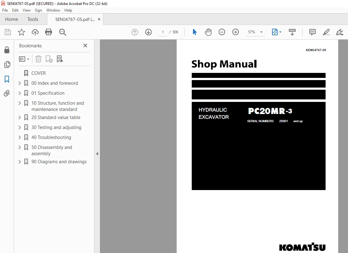
Komatsu Hydraulic Excavator PC20MRX-3 Shop Manual SEN04767-05 – PDF DOWNLOAD
$30.95
Komatsu Hydraulic Excavator PC20MRX-3 Shop Manual SEN04767-05 – PDF DOWNLOAD
SERIAL NUMBERS 20001 and up
Description
Komatsu Hydraulic Excavator PC20MRX-3 Shop Manual SEN04767-05 – PDF DOWNLOAD
FILE DETAILS:
Komatsu Hydraulic Excavator PC20MRX-3 Shop Manual SEN04767-05 – PDF DOWNLOAD
Language : English
Pages :506
Downloadable : Yes
File Type : PDF
DESCRIPTION:
Komatsu Hydraulic Excavator PC20MRX-3 Shop Manual SEN04767-05 – PDF DOWNLOAD
SERIAL NUMBERS 20001 and up
1. General precautions
k Mistakes in operation are extremely dangerous. Read the Operation and Maintenance Manual carefully before operating the machine. In addition, read this manual and understand its contents before starting the work.
TABLE OF CONTENTS:
Komatsu Hydraulic Excavator PC20MRX-3 Shop Manual SEN04767-05 – PDF DOWNLOAD
SERIAL NUMBERS 20001 and up
COVER 1
00 Index and foreword 3
100 Index 3
Composition of shop manual 4
Table of contents 6
200 Foreword and general information 11
Safety notice 12
How to read the shop manual 17
Explanation of terms for maintenance standard 19
Handling of electric equipment and hydraulic component 21
Handling of connectors newly used for engines 30
How to read electric wire code 33
Precautions when carrying out operation 36
Method of disassembling and connecting push-pull type coupler 39
Standard tightening torque table 42
01 Specification 53
100 Specification and technical data 53
Specification dimension drawing 54
Working range drawing 55
Specifications 56
Weight table 59
Table of fuel, coolant and lubricants 61
10 Structure, function and maintenance standard 63
100 Engine and cooling system 63
PTO 64
Cooling system 66
200 Power train 69
Power train 70
Swing circle 71
300 Undercarriage and frame 73
Track frame 74
Idler cushion 75
Idler 76
Track roller 78
Sprocket 79
Track shoe 80
401 Hydraulic system, Part 1 83
Hydraulic components layout drawing 84
Hydraulic tank and filter 85
Center swivel joint 86
Travel motor 87
Hydraulic cylinder 96
Solenoid valve 99
402 Hydraulic system, Part 2103
Hydraulic pump104
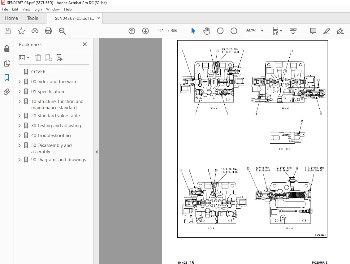
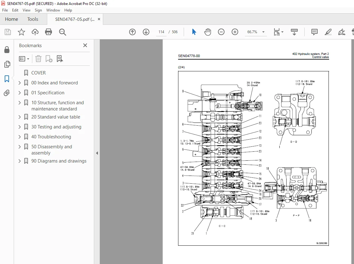
Control valve110
403 Hydraulic system, Part 3123
CLSS124
Operation for each function and valve128
Swing motor148
PPC valve159
500 Work equipment169
Work equipment171
Dimensions of each part of work equipment174
600 Cab and its attachments179
Floor180
700 Electrical system183
Engine control system184
Electric control system186
KOMTRAX system191
Component parts of system194
Monitor system195
Sensors198
20 Standard value table201
100 Standard service value table201
Standard value table for engine related parts202
Standard value table for chassis related parts203
30 Testing and adjusting215
100 Testing and adjusting215
List of testing, adjusting, and troubleshooting tools217
Measuring engine speed220
Adjusting valve clearance221
Measuring compression pressure222
Measuring engine oil pressure223
Testing and adjusting fuel injection timing224
Bleeding air from fuel circuit226
Testing and adjusting fan belt tension227
Adjusting fuel control lever linkage228
Measurement of clearance in swing circle bearings229
Testing and adjusting track shoe tension230
Testing and adjusting oil pressures in work equipment, travel, swing, and blade circuits232
Measuring control circuit basic pressure235
Testing and adjusting pump LS differential pressure236
Measuring solenoid valve output pressure238
Measuring PPC valve output pressure240
Adjusting play of work equipment and swing PPC valves242
Measuring swing holding brake release pressure242
Measurement of oil leakage from cylinder244
Releasing residual pressure from hydraulic circuit246
Bleeding air from cylinder246
Pressurizing hydraulic tank247
How to open and close (tilt) floor248
Inspection procedures for diode252
How to start operation of KOMTRAX terminal253
Lamp display of KOMTRAX terminal257
Preparation work for troubleshooting of electrical system261
40 Troubleshooting263
100 General Information on troubleshooting263
Points to remember when troubleshooting264
Sequence of events in troubleshooting265
Check before troubleshooting266
Classification and troubleshooting steps267
Probable problems and troubleshooting No268
Connection table for connector pin numbers271
T- branch box and T- branch adapter table307
200 Troubleshooting of electrical system (E-mode)311
Before starting E-mode troubleshooting312
Information contained in troubleshooting table314
E- 1 Engine does not start315
E- 2 Engine does not stop321
E- 3 When lock lever is in FREE position, whole work equipment, travel, swing, and blade systems do not work323
E- 4 When lock lever is in LOCK position, whole work equipment, travel, swing, and blade systems work326
E- 5 When machine starts traveling, travel alarm does not sound328
E- 6 When machine stops traveling, travel alarm does not stop sounding331
E- 7 Windshield wiper does not operate [Cab specification]333
E- 8 Windshield washer does not operate [Cab specification]335
E- 9 Heater does not operate337
300 Troubleshooting of hydraulic and mechanical system (H-mode)343
Information contained in troubleshooting table345
H- 1 Speed or power of whole work equipment, travel, swing, and blade is low346
H- 2 Engine speed lowers extremely or engine stalls349
H- 3 Whole work equipment, travel system, swing system, and blade do not work350
H- 4 Abnormal sound comes out from around hydraulic pump353
H- 5 Fine control performance or response is low353
H- 6 Speed or power of boom is low354
H- 7 Speed or power of arm is low355
H- 8 Speed or power of bucket is low356
H- 9 Speed or power of boom swing is low357
H-10 Work equipment does not move in its single operation358
H-11 Work equipment hydraulic drift is large358
H-12 Time lag of work equipment is large359
H-13 In compound operation of work equipment, speed of part loaded more is low359
H-14 Machine deviates during travel360
H-15 Travel speed or travel power is low362
H-16 Machine is not steered well or steering power is low362
H-17 Travel speed does not change363
H-18 Travel motor does not work (one side only)363
H-19 Speed or power of swing is low364
H-20 Machine does not swing366
H-21 Swing acceleration performance is low368
H-22 Machine overruns when it stops swinging369
H-23 Large shock is made when machine stops swinging370
H-24 When upper structure stops swinging, it makes large sound370
H-25 Hydraulic drift of swing is large371
H-26 Speed or power of blade is low372
H-27 Blade does not move373
H-28 Hydraulic drift of blade is large373
400 Troubleshooting of engine (S-mode)375
Troubleshooting charts376
500 Troubleshooting of Machine monitor System(M-mode)383
Before starting M-mode troubleshooting384
Information contained in troubleshooting table386
M- 1 When starting switch is turned ON, no monitor/gauge operates387
M- 2 When starting switch is turned ON, some monitors/gauges do not operate389
M- 3 Caution buzzer does not sound or does not stop sounding390
M- 4 While engine is running, engine oil pressure monitor flashes392
M- 5 While engine is running, charge level monitor flashes393
M- 6 Preheating system does not operate395
M- 7 Coolant temperature gauge does not indicate normally397
M- 8 Fuel level gauge does not indicate normally400
M- 9 Service meter does not operate while engine is running402
M-10Travel speed shifting system does not operate normally403
M-11 Machine monitor night lamp and working lamp do not right up406
50 Disassembly and assembly411
100 General information on disassembly and assembly411
How to read this manual412
Coating materials list414
Special tool list417
200 Engine and cooling system421
Removal and installation of fuel injection pump assembly422
Removal and installation of radiator and hydraulic oil cooler assembly424
Removal and installation of engine and hydraulic pump assembly428
300 Power train433
Removal and installation of swing circle assembly434
400 Undercarriage and frame437
Removal and installation of track shoe assembly438
Disassembly and assembly of idler assembly439
Disassembly and assembly of recoil spring441
Disassembly and assembly of track roller assembly444
Removal and installation of floor frame assembly445
Removal and installation of revolving frame assembly449
500 Hydraulic system453
Disassembly and assembly of control valve assembly454
Removal and installation of center swivel joint assembly458
Disassembly and assembly of center swivel joint assembly460
Removal and installation of swing motor and swing machinery assembly462
Disassembly and assembly of hydraulic cylinder assembly463
600 Work equipment469
Removal and installation of blade assembly470
Removal and installation of work equipment assembly471
700 Cab and its attachments475
Removal and installation of front window assembly476
Removal and installation of operator’s cab glass (stuck glass)477
800 Electric system487
Removal and installation of KOMTRAX terminal488
90 Diagrams and drawings491
100 Hydraulic diagrams and drawings491
Hydraulic circuit diagram493
200 Electrical diagrams and drawings497
Electrical circuit diagram (1/2)499
Electrical circuit diagram (2/2)501
Connector list and stereogram503
IMAGES PREVIEW OF THE MANUAL:
S.M 22/12/24