
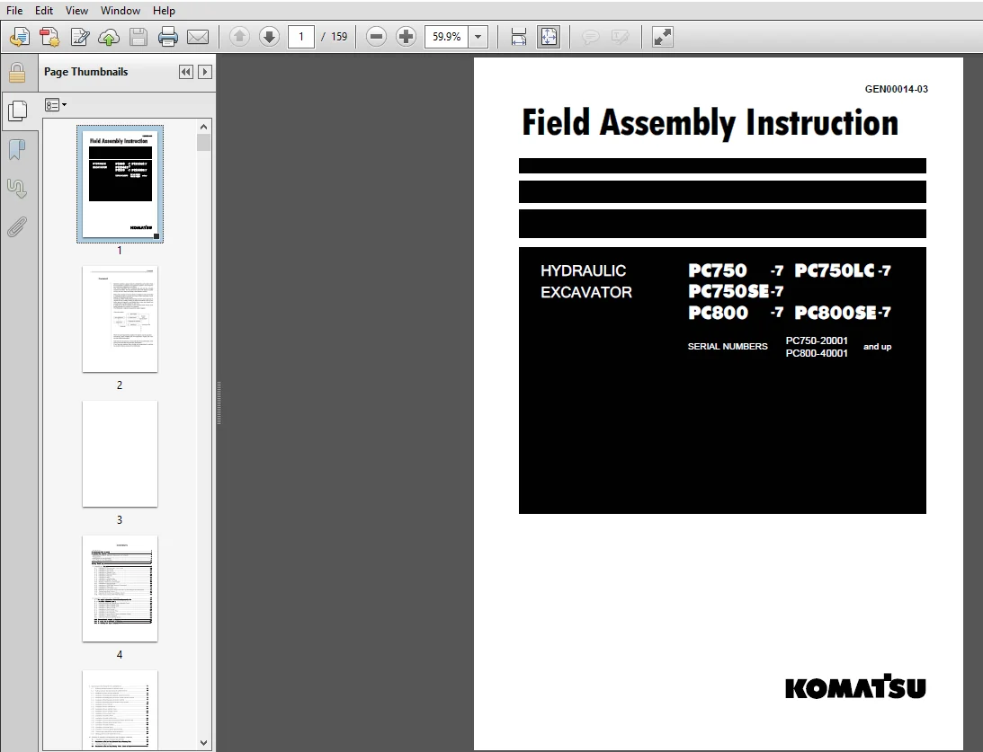
Komatsu Hydraulic Excavator PC750-7 PC750LC-7 PC750SE-7 PC800 PC800SE-7 Field Assembly Instruction Manual – PDF DOWNLOAD
Original price was: $56.95.$15.95Current price is: $15.95.
Komatsu Hydraulic Excavator PC750-7 PC750LC-7 PC750SE-7 PC800 PC800SE-7 Field Assembly Instruction Manual
SERIAL NUMBERS:
PC750-20001 and up
PC800-40001 and up
Description
Komatsu Hydraulic Excavator PC750-7 PC750LC-7 PC750SE-7 PC800 PC800SE-7 Field Assembly Instruction Manual
FILE DETAILS:
Komatsu Hydraulic Excavator PC750-7 PC750LC-7 PC750SE-7 PC800 PC800SE-7 Field Assembly Instruction Manual
Brands: Komatsu
Equipment Type: Hydraulic Excavator
Manuals Type: Field Assembly Instruction Manual
Machine Model: PC750-7 PC750LC-7 PC750SE-7 PC800 PC800SE-7
Serial Number: PC750-20001 and up, PC800-40001 and up
Book Code: GEN00014-03
Language: English
Pages: 159
File Format: Portable Document Format (PDF)
DESCRIPTION:
Komatsu Hydraulic Excavator PC750-7 PC750LC-7 PC750SE-7 PC800 PC800SE-7 Field Assembly Instruction Manual
FOREWORD:
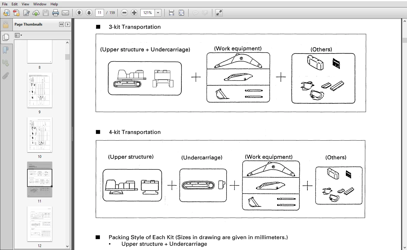
- Since this machine is large in size, it is divided into some units to meet the transportation conditions and regulations applied to the transportation route when shipped from our factory. This manual describes how to assemble the units into the complete machine in the field.
- We hope that this machine will display its quality and you will use it safely according to the operation manual. Many units are large in size and heavy in weight and may be handled in a dangerous place or posture and many workers may have to work together to sling them with cranes.
- Accordingly. before starting the assembly work. the work supervisor is required to hold a safety meeting to oblige the workers to put on protective gear and appoint a work leader and a crane work signal man and allot roles to all the workers for safe work
- . In particular. the above meeting is more important when worker of different languages and customs work together. When the work equipment ls installed. the engine must be operated. Accordingly. before installing the work equipment. inspect and maintain the machine thoroughly.
- Note that this manual does not describe the whole specification of the machine but describes only the basic specification. if you have any question when dividing and transporting the machine by yourself in future. ask one of our distributors.
TABLE OF CONTENTS:
Komatsu Hydraulic Excavator PC750-7 PC750LC-7 PC750SE-7 PC800 PC800SE-7 Field Assembly Instruction Manual
COVER
....................................................................................  1
Foreword
.................................................................................  2
CONTENTS .................................................................................  4
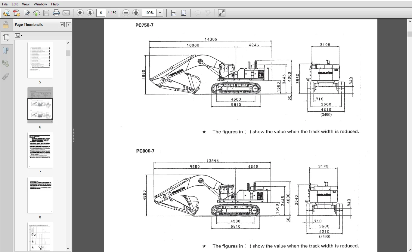
SPECIFICATIONS
...........................................................................  6
Precautions for field assembly............................................................  7
DISPOSAL OF REMOVED PARTS.................................................................  8
Assembling Procedures, Applicable Equipment and Schedule
.................................  9
TRANSPORTATION
........................................................................... 11
List of Tools for Field Assembling
....................................................... 17
TIGHTENING TORQUE......................................................................... 18
COATING MATERIALS LIST.................................................................... 22
A. ASSEMBLY OF CHASSIS.................................................................... 24
	A-1. Installation of Left and Right Track Frames ..................................... 25
	A-2. Installation of Travel Pipe ..................................................... 28
	A-3. Installation of Top Guard ....................................................... 31
	A-4. Installation of Radiator Cover .................................................. 32
	A-5. Installation of Rearview Mirror ................................................. 33
	A-6. Installation of Handrail ........................................................ 37
	A-7. Installation of Step ............................................................ 40
	A-8. Installation of Left Side Step .................................................. 41
	A-9. Installation of Muffler Tail Tube ............................................... 42
	A-10. Sticking of Sheet (to Counterweight) ........................................... 43
	A-11. Installation of Counterweight .................................................. 44
	A-12. Installation of ORBCOMM Antenna (if equipped) .................................. 45
	A-13. Installation of Step Light ..................................................... 46
	A-14. Installation of Travel Pipe Cover .............................................. 48
	A-15. Extension of Track Frame Gauge (Only When 3-split Packages are transported) .... 49
	A-16. Testing Track Shoe Tension ..................................................... 52
	A-17. Installation of Oil Amount and Water Amount .................................... 55
	A-18. Parts to be Touched up After Field Assembly .................................... 57
B.ASSEMBLING OF WORK EQUIPMENT OF BACKHOE
................................................ 58
	B-1. Pulling Out of Boom Foot Pin, and Boom Cylinder Foot Pin......................... 59
	B-2. Installation of Boom Assembly.................................................... 60
	B-3. Relieving Remaining Pressure from Hydraulic Circuit ............................. 61
	B-4. B-2. Installation of Boom Cylinder Foot.......................................... 62
	B-5.  Installation of Boom Cylinder Hose
............................................. 63
	B-6.  Installation of Boom Cylinder
.................................................. 64
	B-7.  Installation of Arm Cylinder
................................................... 65
	B-8.  Installation of Arm Cylinder Hose
.............................................. 66
	B-9. Installation of Arm Assembly  ................................................... 67
	B-10. Installation of Hose between Boom and Bucket Cylinder
.......................... 69
	B-11. Installation of Bucket Assembly
................................................ 70
	B-12. Lubrication Piping to Work Equipment
........................................... 71
	B-13. Connection of Wiring of Work Equipment.......................................... 72
	B-14. Greasing after Assembling Work Equipment........................................ 73
	B-15. Air Bleeding from Hydraulic Cylinder............................................ 74
C. ASSEMBLING OF WORK EQUIPMENT OF LOADING SHOVEL
........................................ 76
	C-1. Releasing residual pressure in hydraulic circuit
................................ 77
	C-2. Pulling out boom foot pin and boom cylinder foot pin
............................ 78
	C-3. Installation of boom and arm assembly
  ......................................... 79
	C-4. Installation of flushing piping between chassis and boom
........................ 80
	C-5. Installation of flushing piping for boom cylinder and arm cylinder
.............. 81
	C-6. Installation of
flushing piping for bucket cylinder ............................. 82
	C-7. Installation of flushing piping for bottom dump cylinder
........................ 83
	C-8. Installation of boom cylinder
................................................... 85
	C-9. Installation of boom cylinder foot
.............................................. 86
	C-10. Installation of boom cylinder hoses
............................................ 87
	C-11. Installation of boom cylinder rod pin
.......................................... 88
	C-12. Installation of arm cylinder hoses
............................................. 89
	C-13. Installation of bucket cylinder
................................................ 90
	C-14. Installation of bucket cylinder hose
........................................... 91
	C-15. Installation of connecting hoses between chassis and boom top .................. 92
	C-16. Installation of bottom dump cylinder hoses
..................................... 93
	C-17. Installation of bucket assembly
................................................ 94
	C-18. Installation of working lamps
.................................................. 96
	C-19. Installation of work equipment grease piping
................................... 97
	C-20. Greasing after assembling of work equipment
.................................... 98
	C-21 Bleeding air from hydraulic cylinder............................................. 99
M. PROCEDURE FOR INSPECTION AND MAINTENANCE AFTER COMPLETION OF ASSEMBLY
.................100
	M-1.Inspection of Oil Level in Hydraulic Tank and Refill..............................101
	M-2.Replacement of Return Filter (Standard Filter to Flushing Filter).................103
	M-3.Flushing of Hydraulic Circuit.....................................................104
	M-4.Replacement of Return Filter (Flushing Filter to Standard Filter).................106
FIELD ASSEMBLY INSPECTION REPORT (Backhoe)
...............................................108
FIELD ASSEMBLY INSPECTION REPORT (Loading Shovel)
........................................134
KOMATSU HYDRAULIC EXCAVATOR PC750-7 PC750LC-7 PC750SE-7 PC800 PC800SE-7 FIELD ASSEMBLY INSTRUCTION MANUAL – PDF DOWNLOAD:
IMAGES PREVIEW OF THE MANUAL:
PLEASE NOTE:
- This is the SAME manual used by the dealers to troubleshoot any faults in your vehicle. This can be yours in 2 minutes after the payment is made.
- Contact us at [email protected] should you have any queries before your purchase or that you need any other service / repair / parts operators manual.




Ameer Samuel –
Easy purchase