
Trusted Business
Verified & Licensed
Virus Free Files
100% Safe Downloads
Secure Payment
SSL Protected
Instant Delivery
Available Immediately
Sale!


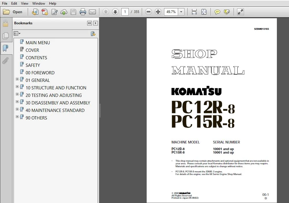
KOMATSU PC12R-8 PC15R-8 SERVICE REPAIR MANUAL (SN:10001 & UP) KOMATSU PC12R-8 PC15R-8 – PDF DOWNLOAD
Original price was: $73.95.$26.95Current price is: $26.95.
- KOMATSU PC12R-8 PC15R-8 SERVICE REPAIR MANUAL
- SERIAL NUMBER:PC12R-8-10001 & UP,PC15R-8-10001 & UP
- PUBLICATION NUMBER:SEBM013103
Instant PDF Download
Available immediately
Save to Your Device
Download & keep forever
Antivirus Scanned
100% virus-free
Trusted Worldwide
175,000+ customers
Description
KOMATSU PC12R-8 PC15R-8 SERVICE REPAIR MANUAL (SN:10001 & UP) KOMATSU PC12R-8 PC15R-8
KOMATSU PC12R-8 PC15R-8 SERVICE REPAIR MANUAL (SN:10001 & UP) KOMATSU PC12R-8 PC15R-8 – PDF DOWNLOAD:
IMAGE PREVIEW:
DESCRIPTION:
KOMATSU PC12R-8 PC15R-8 SERVICE REPAIR MANUAL (SN:10001 & UP) KOMATSU PC12R-8 PC15R-8
- This shop manual has been prepared as an aid to improve the quality of repairs by giving the serviceman an accurate understanding of the product and by showing him the correct way to perform repairs and make judgements. Make sure you understand the contents of this manual and use it to full effect at every opportunity.
- This shop manual mainly contains the necessary technical information for operations performed in a service workshop. For ease of understanding, the manual is divided into the following chapters; these chapters are further divided into the each main group of components.
- STRUCTURE AND FUNCTION
This section explains the structure and function of each component. It serves not only to give an understanding of the structure, but also serves as reference material for troubleshooting. - TESTING AND ADJUSTING
This section explains checks to be made before and after performing repairs, as well as adjustments to be made at completion of the checks and repairs. Troubleshooting charts correlating “Problems” to “Causes” are also included in this section. - DISASSEMBLY AND ASSEMBLY
This section explains the order to be followed when removing, installing, disassembling or assembling each component, as well as precautions to be taken for these operations. - MAINTENANCE STANDARD
This section gives the judgement standards when inspecting disassembled parts.
TABLE OF CONTENTS:
KOMATSU PC12R-8 PC15R-8 SERVICE REPAIR MANUAL (SN:10001 & UP) KOMATSU PC12R-8 PC15R-8
MAIN MENU.....................................................................................................................  0
COVER.........................................................................................................................  1
CONTENTS......................................................................................................................  2
SAFETY........................................................................................................................  5
00 FOREWORD...................................................................................................................  7
01 GENERAL.................................................................................................................... 25
	General assembly drawing.................................................................................................. 26
	Specifications............................................................................................................ 30
	List of lubricant and water............................................................................................... 34
10 STRUCTURE AND FUNCTION..................................................................................................... 35
	Power Train............................................................................................................... 36
	Swing circle.............................................................................................................. 37
	Track frame and recoil spring............................................................................................. 38
	Hydraulic piping.......................................................................................................... 39
	Hydraulic tank............................................................................................................ 40
	Hydraulic pump............................................................................................................ 41
	Control valve (PC12R-8)................................................................................................... 45
	CLSS (PC12R-8)............................................................................................................ 53
	Control valve (PC15R-8)................................................................................................... 76
	CLSS (PC15R-8)............................................................................................................ 84
	Center swivel joint.......................................................................................................105
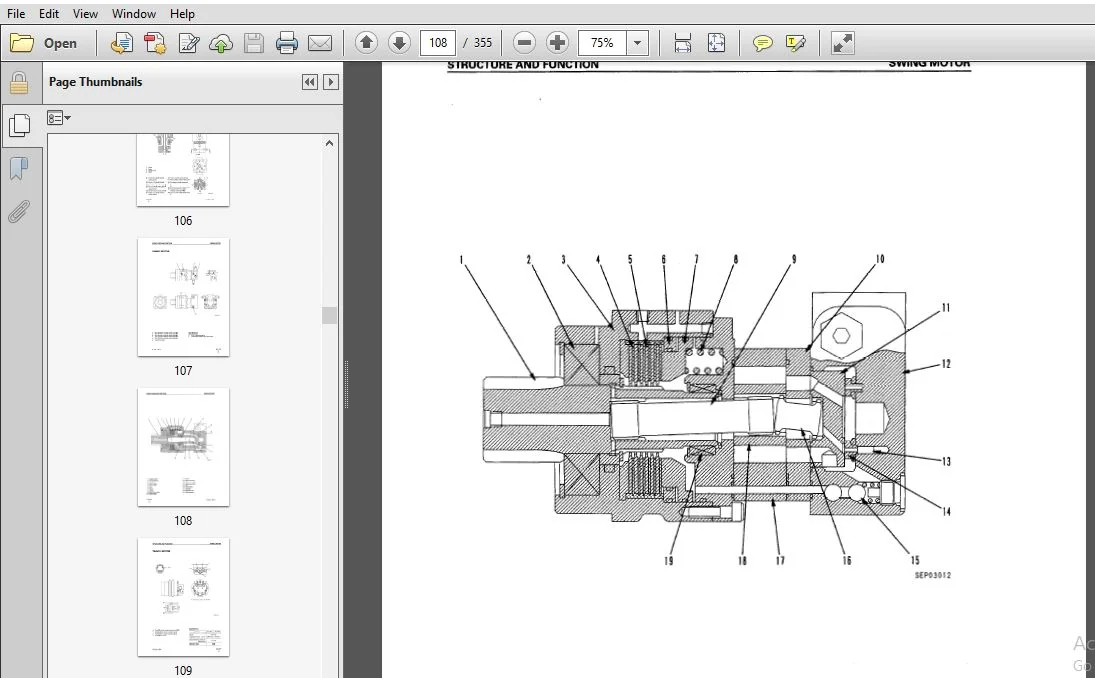
	Swing motor...............................................................................................................107
	Travel motor..............................................................................................................109
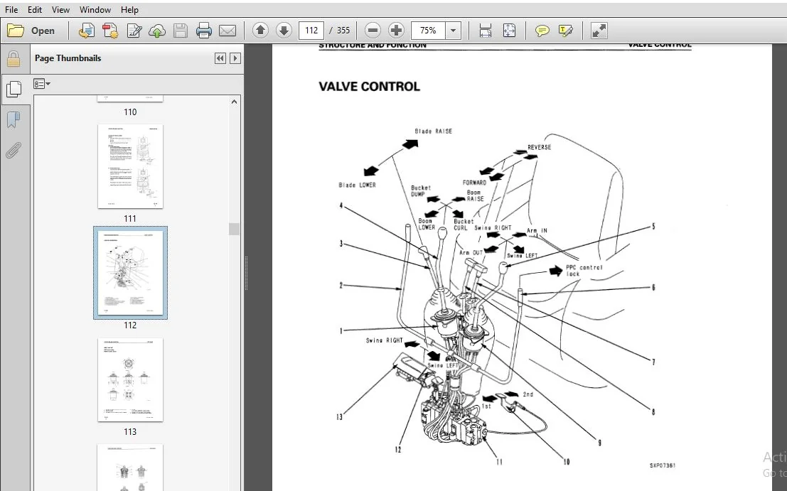
	Valve control.............................................................................................................112
	PPC valve.................................................................................................................113
	Work equipment............................................................................................................117
	Machine monitor system....................................................................................................118
20 TESTING AND ADJUSTING......................................................................................................121
	STANDARD VALUE TABLE......................................................................................................122
	Standard value table for engine related parts.............................................................................122
	Standard value table for chassis related parts............................................................................124
	Standard value table for electrical parts.................................................................................138
	TESTING AND ADJUSTING.....................................................................................................140
		Tools for testing, adjusting, and troubleshooting.....................................................................141
		Measuring engine speed................................................................................................142
		Measuring exhaust color...............................................................................................143
		Adjusting valve clearance.............................................................................................144
		Measuring compression pressure........................................................................................145
		Testing and adjusting fuel injection timing...........................................................................146
		Measuring engine oil pressure.........................................................................................147
		Testing and adjusting fan belt tension................................................................................148
		Testing and adjusting fuel control lever..............................................................................149
		Measuring sprocket wear...............................................................................................150
		Testing and adjusting track shoe tension..............................................................................151
		Testing and adjusting hydraulic pressure in work equipment, swing, travel circuit ....................................152
		Testing and adjusting LS differential pressure........................................................................158
		Adjusting PC valve spring.............................................................................................160
		Testing and adjusting control circut pressure.........................................................................161
		Measuring output pressure of PPC lock valve and travel boost valve....................................................163
		Testing PPC valve output pressure and swing holding brake inlet port pressure.........................................164
		Adjusting work equipment, swing PPC valve ............................................................................166
		Testing and adjusting travel deviation................................................................................167
		Measuring oil leakage inside work equipment cylinder..................................................................168
		Releasing remaining pressure from hydraulic circuit...................................................................169
		Releasing remaining pressure from hydraulic tank .....................................................................169
		Pressurizing hydraulic tank...........................................................................................169
		Bleeding air..........................................................................................................170
	TROUBLESHOOTING...........................................................................................................172
		Type of connector and position of installation........................................................................173
		Connection table for connector pin numbers ...........................................................................176
		Troubleshooting of engine electrical system (E mode)..................................................................186
			E-Mode related electrical circuit diagram.........................................................................187
			E-1 Engine does not start.........................................................................................188
				a) When starting motor does not turn (starting system)........................................................188
				b) When starting motor turns (engine stop solenoid system)....................................................190
			E-2 Engine does not stop..........................................................................................192
		Troubleshooting of hydraulic, mechanical system (H mode)..............................................................193
			Table of failure modes and causes.................................................................................194
			H- 1 Speeds of all work equipment, swing, travel are slow or lack power...........................................198
			H- 2 There is excessive drop in engine speed, or engine stalls....................................................200
			H- 3 No work equipment, travel, swing move........................................................................201
			H- 4 Abnormal noise generated (from around pump)..................................................................202
			H- 5 Fine control ability is poor or response is poor (PC15R).....................................................202
			H- 6 Boom is slow or lacks power..................................................................................203
			H- 7 Arm is slow or lacks power...................................................................................203
			H- 8 Bucket is slow or lacks power................................................................................204
			H- 9 Boom swing is slow or lacks power............................................................................204
			H-10 Blade is slow or lacks power.................................................................................205
			H-11 Boom, arm, bucket do not move (boom swing, blade, travel and swing are normal)...............................205
			H-12 Excessive hydraulic drift (boom, arm, bucket, boom swing, blade).............................................206
				a) Boom, bucket, boom swing, blade............................................................................206
				b) Arm........................................................................................................206
			H-13 Excessive time lag (engine at low idling)....................................................................206
				a) Boom, arm..................................................................................................206
				b) Bucket.....................................................................................................206
			H-14 In compound operations, work equipment with larger load is slow..............................................207
			H-15 Travel deviation.............................................................................................208
				a) Deviation in normal travel.................................................................................208
				b) Deviation when starting....................................................................................208
			H-16 Travel speed is slow or lacks power..........................................................................209
			H-17 Steering does not turn easily................................................................................209
			H-18 Travel speed does not switch.................................................................................210
			H-19 Travel does not move (one side only).........................................................................210
			H-20 Swing speed is slow or lacks power...........................................................................211
				a) Speed is slow or lacks power in both directions............................................................211
				b) Speed is slow or lacks power in one direction only (left or right).........................................211
			H-21 Does not swing...............................................................................................212
				a) Does not swing in either direction.........................................................................212
				b) Does not swing in one direction (left or right)............................................................212
			H-22 Swing acceleration is poor...................................................................................213
				a) Acceleration is poor in both directions....................................................................213
				b) Acceleration is poor in one direction only (left or right).................................................213
			H-23 Excessive overrun when stopping swing........................................................................214
				a) Overrun when stopping is excessive in both directions......................................................214
				b) Overrun when stopping is excessive in one direction only (left or right)...................................214
			H-24 Excessive shock when stopping swing (in one direction only)..................................................214
			H-25 Excessive abnormal noise when stopping swing.................................................................215
			H-26 Excessive hydraulic drift of swing...........................................................................215
		Troubleshooting of machine monitor system (M mode)....................................................................216
			Electrical circuit diagram for M Mode related parts...............................................................217
			M-1 Abnormality in engine oil pressure caution lamp system........................................................218
				a) Lamp does not light up when starting switch is turned ON...................................................218
				b) Lamp lights up when engine is running (engine oil pressure is normal)......................................218
			M-2 Abnormality in charge caution lamp system.....................................................................220
				a) Lamp does not light up when starting switch is turned ON...................................................220
				b) Lamp lights up when engine is running (battery charge is normal)...........................................220
			M-3 Abnormality in engine water temperature caution lamp system...................................................222
				a) Lamp does not stay lighted up for 3 seconds when starting switch is turned ON..............................222
				b) Lamp does not go out after starting switch has been at ON for 3 seconds....................................222
				c) Lamp lights up when engine is running (engine water temperature is normal).................................223
			M-4 Abnormality in preheating pilot lamp..........................................................................224
				a) Lamp does not light up when starting switch is turned to HEAT..............................................224
				b) Lamp does not go out when starting switch is at HEAT and preheating time (approx. 18 sec.) is completed....224
				c) Lamp lights up when starting switch is at position other than HEAT.........................................225
			M-5 Abnormality in fuel gauge system..............................................................................226
				a) Gauge does not go up from E when fuel is added to fuel tank................................................226
				b) Gauge does not go down from F even when there is no fuel in fuel tank......................................226
				c) Fuel level does not match gauge display....................................................................227
			M-6 Abnormality in service meter system...........................................................................228
				a) Service meter does not advance when starting switch is at ON...............................................228
				b) Service meter advances when starting switch is at OFF......................................................228
				c) Pilot lamp does not flash when service meter is advancing..................................................228
			M-7 Abnormality in night lighting system..........................................................................230
				a) Night lighting does not light up when lamp switch is turned ON.............................................230
				b) Night lighting lights up when lamp switch is turned OFF ...................................................230
30 DISASSEMBLY AND ASSEMBLY...................................................................................................232
	Method of using manual....................................................................................................234
	Precautions when carrying out operation...................................................................................235
	Special tool list.........................................................................................................237
	Starting motor............................................................................................................238
		Removal and installation..............................................................................................238
	Alternator ...............................................................................................................239
		Removal and installation..............................................................................................239
	Fuel injection pump ......................................................................................................240
		Removal and installation..............................................................................................240
	Nozzle holder ............................................................................................................241
		Removal and installation..............................................................................................241
	Water pump ...............................................................................................................242
		Removal and installation..............................................................................................242
	Thermostat ...............................................................................................................243
		Removal and installation..............................................................................................243
	Engine front seal.........................................................................................................244
		Removal and installation..............................................................................................244
	Engine rear seal..........................................................................................................245
		Removal...............................................................................................................245
		Installation..........................................................................................................246
	Cylinder head.............................................................................................................247
		Removal...............................................................................................................247
		Installation..........................................................................................................248
	Radiator..................................................................................................................249
		Removal...............................................................................................................249
		Installation..........................................................................................................250
	Engine, hydraulic pump....................................................................................................251
		Removal...............................................................................................................232
		Installation..........................................................................................................253
	Fuel tank.................................................................................................................254
		Removal and installation..............................................................................................254
	Damper....................................................................................................................255
		Removal and installation..............................................................................................255
	Center swivel joint.......................................................................................................256
		Removal and installation..............................................................................................256
		Disassembly and assembly..............................................................................................257
	Travel motor..............................................................................................................258
		Removal and installation..............................................................................................258
	Sprocket..................................................................................................................259
		Removal and installation..............................................................................................259
	Swing motor...............................................................................................................260
		Removal and installation..............................................................................................260
	Revolving frame...........................................................................................................261
		Removal...............................................................................................................261
		Installation..........................................................................................................262
	Swing circle..............................................................................................................263
		Removal and installation..............................................................................................263
	Idler.....................................................................................................................264
		Removal and installation..............................................................................................264
		Disassembly...........................................................................................................265
		Assembly..............................................................................................................266
	Idler cushion (rubber shoe)...............................................................................................267
		Removal and installation..............................................................................................267
		Disassembly and assembly..............................................................................................268
	Idler cushion (steel shoe)................................................................................................269
		Disassembly...........................................................................................................232
		Assembly..............................................................................................................270
	Track roller..............................................................................................................271
		Removal and installation..............................................................................................271
		Disassembly and assembly..............................................................................................272
	Rubber shoe...............................................................................................................273
		Removal and installation..............................................................................................273
	Steel shoe................................................................................................................274
		Removal and installation..............................................................................................274
	Hydraulic tank............................................................................................................275
		Removal...............................................................................................................275
		Installation..........................................................................................................276
	Hydraulic oil cooler......................................................................................................277
		Removal and installation..............................................................................................277
	Hydraulic pump............................................................................................................278
		Removal and installation..............................................................................................278
	Control valve.............................................................................................................279
		Removal...............................................................................................................279
		Installation..........................................................................................................280
		Disassembly...........................................................................................................281
		Assembly..............................................................................................................286
	PPC valve.................................................................................................................293
		Removal and installation..............................................................................................293
		Disassembly...........................................................................................................294
		Assembly..............................................................................................................295
	Boom cylinder.............................................................................................................296
		Removal...............................................................................................................296
		Installation..........................................................................................................297
	Arm cylinder..............................................................................................................298
		Removal...............................................................................................................298
		Installation..........................................................................................................299
	Bucket cylinder...........................................................................................................300
		Removal...............................................................................................................300
		Installation..........................................................................................................301
	Swing cylinder............................................................................................................302
		Removal...............................................................................................................302
		Installation..........................................................................................................303
	Blade cylinder............................................................................................................304
		Removal and installation..............................................................................................304
	Hydraulic cylinder........................................................................................................305
		Disassembly...........................................................................................................305
		Assembly..............................................................................................................308
	Work equipment............................................................................................................312
		Removal...............................................................................................................312
		Installation..........................................................................................................313
	Bucket....................................................................................................................314
		Removal and installation..............................................................................................314
	Arm.......................................................................................................................315
		Removal...............................................................................................................315
		Installation..........................................................................................................316
	Bucket, arm...............................................................................................................317
		Removal...............................................................................................................317
		Installation..........................................................................................................318
	Boom......................................................................................................................319
		Removal ..............................................................................................................319
		Installation..........................................................................................................320
	Swing bracket.............................................................................................................321
		Removal...............................................................................................................321
		Installation..........................................................................................................322
	Blade.....................................................................................................................323
		Removal and installation..............................................................................................323
	Canopy....................................................................................................................324
		Removal and installation..............................................................................................324
40 MAINTENANCE STANDARD.......................................................................................................325
	Swing circle..............................................................................................................326
	Track frame, recoil spring................................................................................................327
	Idler.....................................................................................................................328
	Track roller..............................................................................................................329
	Track shoe................................................................................................................330
	Hydraulic pump (PC15R-8)..................................................................................................332
	Control valve (PC12R-8)...................................................................................................333
	Control valve (PC15R-8)...................................................................................................339
	Center swivel joint.......................................................................................................345
	Swing motor...............................................................................................................346
	PPC valve.................................................................................................................347
	Hydraulic cylinder........................................................................................................348
	Work equipment............................................................................................................350
90 OTHERS.....................................................................................................................352
	Hydraulic circuit diagram PC12R-8.........................................................................................353
	Hydraulic circuit diagram PC15R-8.........................................................................................354
	Electric circuit diagram PC12R,15R-8......................................................................................355
PLEASE NOTE:
⦁ This is the same manual used by the DEALERSHIPS to SERVICE your vehicle.
⦁ The manual can be all yours – Once payment is complete, you will be taken to the download page from where you can download the manual. All in 2-5 minutes time!!
⦁ Need any other service / repair / parts manual, please feel free to contact us at heydownloadss @gmail.com . We may surprise you with a nice offer




Elian Reese –
It was nice.