
Komatsu PC130-8 Hydraulic Excavator Shop Manual – Complete Service Repair PDF
Original price was: $39.95.$24.95Current price is: $24.95.
The complete Komatsu PC130-8 Hydraulic Excavator Shop Manual covering specifications, structure and function, standard values, testing and adjusting, troubleshooting, disassembly and assembly, and full hydraulic/electrical diagrams. Serial number 80001 and up. Engine SAA4D95LE-5. Instant PDF download.
Description
Komatsu PC130-8 Shop Manual – Full Workshop Coverage
This Komatsu PC130-8 Shop Manual is the complete workshop service and repair guide for the PC130-8 hydraulic excavator, serial number 80001 and up. It brings together the full set of Komatsu shop manual sections — from specification and technical data through to disassembly and assembly — in a single downloadable PDF. Whether you are servicing the SAA4D95LE-5 diesel engine, troubleshooting a hydraulic fault code, or overhauling the travel motor, this manual provides the procedures, specifications, and reference data needed to complete the work correctly.
File Details
- Manual type: Shop Manual (Workshop Service and Repair)
- Brand: Komatsu
- Model: PC130-8 Hydraulic Excavator
- Serial number range: 80001 and up
- Engine: Komatsu SAA4D95LE-5 Diesel Engine
- Language: English
- File format: PDF
- Document numbers: SEN03763 through SEN03785 series
- Publication date: 2007-2010 (revisions as marked)
- Page count: 1000+ pages
Chapters Covered
- 00 Index and foreword — Composition of shop manual, safety notice, how to read the shop manual, explanation of terms for maintenance standard, handling of electric equipment and hydraulic components, handling of connectors newly used for engines, how to read electric wire code, precautions when carrying out operation, method of disassembling and connecting push-pull type coupler, standard tightening torque table, conversion table
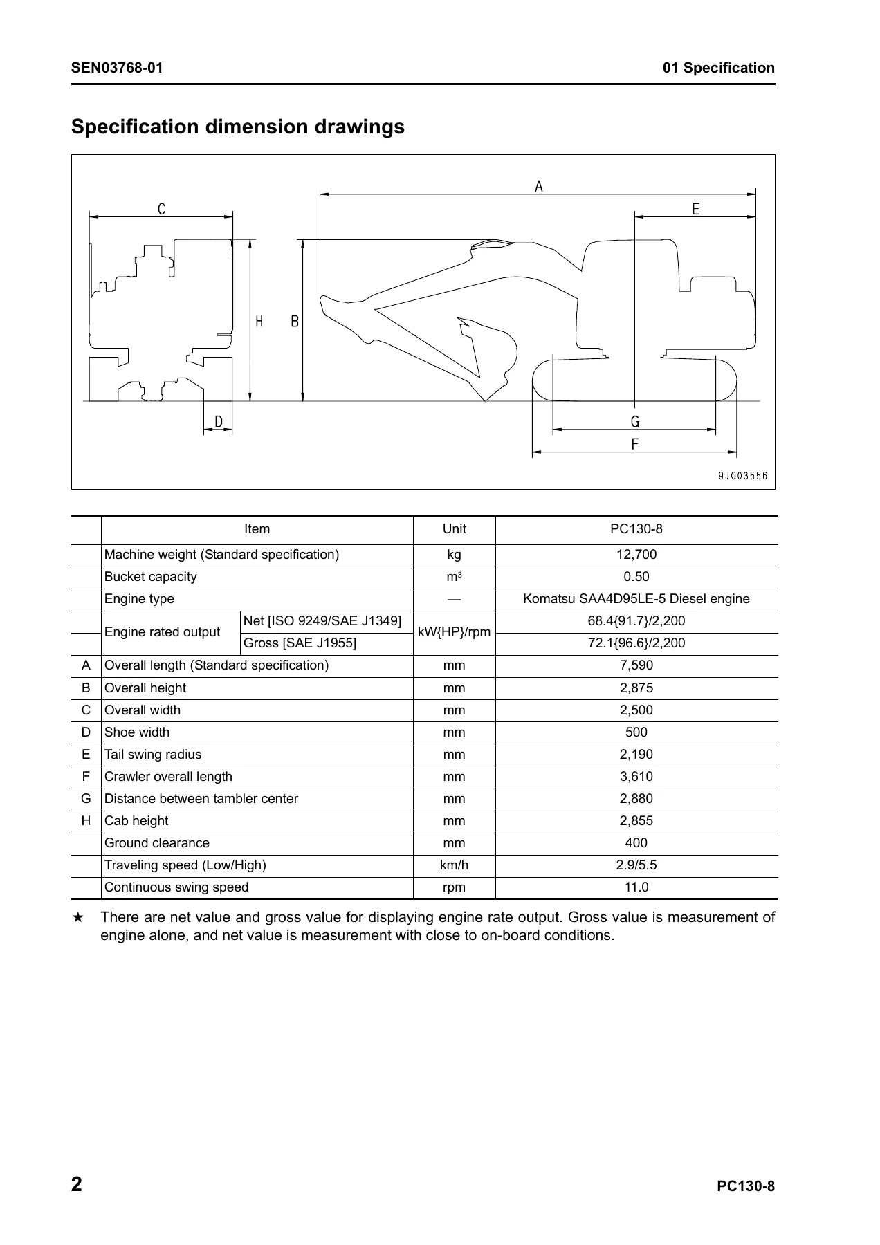
- 01 Specification — Specification dimension drawings, working range diagram, specifications, list of weights, list of lubricant and coolant to be filled
- 10 Structure, function and maintenance standard — Engine mount, PTO, cooling system, power train, swing circle, swing machinery, track frame, idler cushion, idler, track roller, carrier roller, sprocket, track shoe, hydraulic equipment layout drawing, valve control, hydraulic tank and filter, hydraulic pump, control valve, CLSS, functions and operation by valve, PPC valve, travel motor, center swivel joint, solenoid valve, accumulator, holding valve, hydraulic cylinder, work equipment, air conditioner, electronic control system, machine monitor system, KOMTRAX system, sensor
- 20 Standard value table — Standard value table for engine related parts, standard value table for chassis related parts
- 30 Testing and adjusting — Tools for testing, adjusting, and troubleshooting, sketches of special tools, testing engine speed, testing exhaust temperature, checking exhaust gas color, adjusting valve clearance, testing compression pressure, testing blow-by pressure, testing engine oil pressure, reduced cylinder mode operation, no-injection cranking, handling fuel system parts, releasing residual pressure from fuel system, testing fuel pressure, testing fuel return rate and fuel leakage, bleeding air from fuel circuit, checking fuel circuit for leakage, testing and adjusting alternator belt tension, checking and adjusting air conditioner compressor belt tension, testing swing circle bearing clearance, checking and adjusting track shoe tension, testing and adjusting oil pressure in work equipment, swing, and travel circuits, testing control circuit basic pressure, testing and adjusting oil pressure in pump PC control circuit, testing and adjusting oil pressure in pump LS control circuit, testing solenoid valve output pressure, testing PPC valve output pressure, adjusting play of work equipment and swing PPC valves, checking parts which cause hydraulic drift of work equipment, testing and adjusting travel deviation, releasing residual pressure from hydraulic circuit, testing oil leakage, bleeding air from each part, checking cab tipping stopper, installation and adjustment of mirrors and camera, inspection of air conditioner Recirc/Fresh air filter
- 40 Troubleshooting — Failure code table and fuse locations, general information on troubleshooting, troubleshooting by failure code (Parts 1-4), troubleshooting of electrical system (E-mode), troubleshooting of hydraulic and mechanical system (H-mode), troubleshooting of engine (S-mode)
- 50 Disassembly and assembly — General information, coating materials list, special tool list, engine and cooling system, power train, undercarriage and frame, hydraulic system, work equipment, cab and its attachments, electrical system
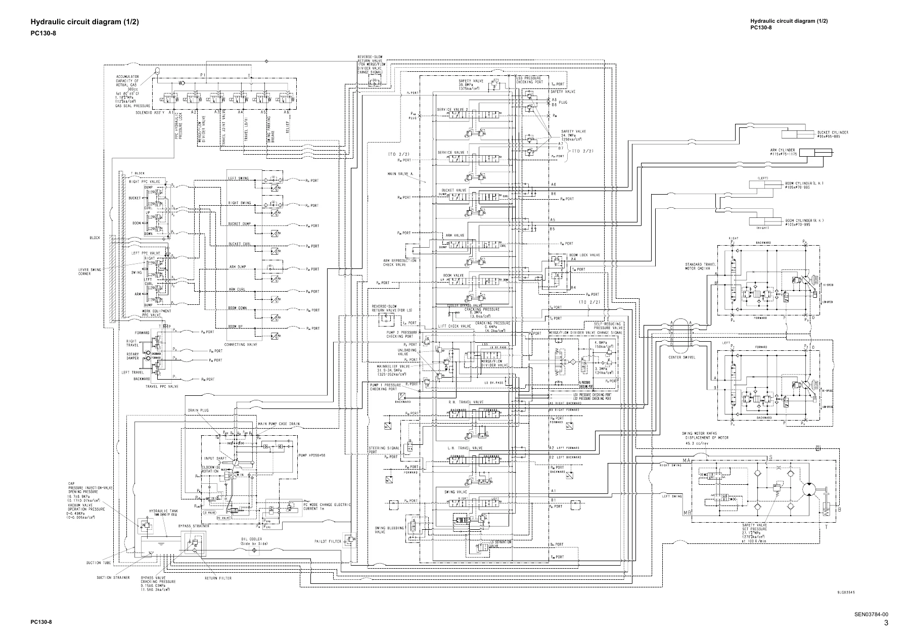
- 90 Diagrams and drawings — Hydraulic circuit diagrams, electrical circuit diagrams, connectors table and arrangement drawing
What This Manual Gives the Technician
The PC130-8 Shop Manual is a comprehensive service document that spans the full maintenance and repair lifecycle of the machine. The specification section provides dimension drawings, working range diagrams, and a complete list of weights and lubricant capacities. The structure and function chapters explain how each major assembly works — from the variable-displacement piston pump and CLSS closed-center load sensing system to the swing machinery, travel motor, and control valve. The standard value tables give the new-machine tolerances and service limits used when inspecting components. The testing and adjusting section walks through pressure tests, speed tests, and component adjustments with the required tools and target values.
The troubleshooting chapters are particularly detailed, covering failure codes by code number, electrical system diagnostics in E-mode, hydraulic and mechanical system diagnostics in H-mode, and engine troubleshooting in S-mode. Each failure code entry lists the trouble, the controller action, the problem that appears on the machine, related information, and possible causes with standard values in the normal state. Disassembly and assembly procedures include special tool lists, tightening torques, coating materials, and step-by-step removal and installation instructions for major components. The hydraulic and electrical circuit diagrams at the end provide the system-level reference needed for tracing circuits and understanding component interaction.
Who This Manual Is For
This Komatsu PC130-8 service manual is intended for technicians, mechanics, and service personnel who need factory-level procedures and specifications for the PC130-8 hydraulic excavator. It is also useful for owners and operators who want to understand the machine’s systems, perform routine testing and adjustment, or diagnose faults using the failure code tables and troubleshooting guides. The manual assumes access to the special tools listed in the disassembly and assembly section and the testing and adjusting section for certain procedures.
Coverage Highlights
The engine section covers the Komatsu SAA4D95LE-5, a 4-cycle water-cooled in-line direct injection diesel engine with turbocharger and air-cooled aftercooler. Valve clearance adjustment, compression pressure testing, blow-by pressure testing, fuel pressure testing, and fuel return rate testing are all documented. The hydraulic system coverage includes the HPD56+56 piston pump with LS valve, PC valve, and PC-EPC valve, the CLSS closed-center load sensing system, pressure compensation valves, and the full control valve assembly with suction safety valves, main relief valve, unload valve, merge-divider valve, and travel junction valve. The electrical system coverage includes the machine monitor system, engine controller, pump controller, KOMTRAX system, and sensor specifications with connector pin numbers and signal classifications.
The disassembly and assembly chapters cover removal and installation of the fuel supply pump, fuel injectors, front and rear oil seals, cylinder head, radiator, aftercooler, oil cooler, engine and work equipment pump, fuel tank, travel motor, final drive, swing motor, swing machinery, swing circle, track roller, idler, recoil spring, track shoe, sprocket, revolving frame, counterweight, center swivel joint, hydraulic tank, control valve, PPC valves, hydraulic cylinders, work equipment, operator cab, cab glass, floor frame, air compressor, air conditioner condenser and unit, KOMTRAX modem, monitor, pump controller, and engine controller.
IMAGES PREVIEW
With over 1,000 pages of technical content, the Komatsu PC130-8 Shop Manual is the definitive reference for maintaining, diagnosing, and repairing this excavator model. It is delivered as an instant PDF download — no shipping, no waiting, and the file can be viewed on any device or printed for workshop use.
Reviews
There are no reviews yet.