Komatsu PC130-8 Hydraulic Excavator Shop Manual SEN03763-10 – PDF DOWNLOAD
Original price was: $53.95.$26.95Current price is: $26.95.
Komatsu PC130-8 Hydraulic Excavator Shop Manual
Description
Komatsu PC130-8 Hydraulic Excavator Shop Manual
FILE DETAILS:
Komatsu PC130-8 Hydraulic Excavator Shop Manual
Brands: Komatsu
Equipment Type: Hydraulic Excavator
Manuals Type: Shop Manual
Machine Model: PC130-8
Serial Number: 80001 and up
Book Code: SEN03763-10
Language: English
Pages: 1023
File Format: Portable Document Format (PDF)
DESCRIPTION:
Komatsu PC130-8 Hydraulic Excavator Shop Manual
HOW TO READ THE SHOP MANUAL:
1. Composition of shop manual
This shop manual contains the necessary technical information for services performed in a workshop. For ease of understanding, the manual is divided into the following sections.
00. FOREWORD:
This section explains the safety and basic information.
01. GENERAL:
This section explains the specifications of the machine.
10. STRUCTURE AND FUNCTION, MAINTENANCE STANDARD:
This section explains the structure, function, and maintenance standard values of each component. The structure and function sub-section explains the structure and function of each component. It serves not only to give an understanding of the structure, but also serves as reference material for troubleshooting. The maintenance standard sub-section explains the criteria and remedies for disassembly and service.
20. TESTING AND ADJUSTING:
Standard value table
This section explains the standard values for new machine and judgement criteria for testing, adjusting, and troubleshooting. This standard value table is used to check the standard values in testing and adjusting and to judge parts in troubleshooting.
Testing and adjusting
This section explains measuring instruments and measuring methods for testing and adjusting, and method of adjusting each part. The standard values and judgement criteria for testing and adjusting
are explained in Testing and adjusting.
Troubleshooting
This section explains how to find out failed parts and how to repair them. The troubleshooting is divided by failure modes. The “S mode” of the troubleshooting related to the engine may be also explained in
the Chassis volume and Engine volume. In this case, see the Chassis volume.
30. DISASSEMBLY AND ASSEMBLY:
This section explains the special tools and procedures for removing, installing, disassembling, and assembling each component, as well as precautions for them. In addition, tightening torque and quantity and weight of coating material, oil, grease, and coolant necessary for the work are also explained.
90. OTHERS (chassis volume)/Repair and replacement of parts (engine volume):
• Chassis volume
This section gives hydraulic circuit diagrams and electrical circuit diagrams.
• Engine volume
This section explains the method of reproducing, repairing, and replacing parts.
TABLE OF CONTENTS:
Komatsu PC130-8 Hydraulic Excavator Shop Manual
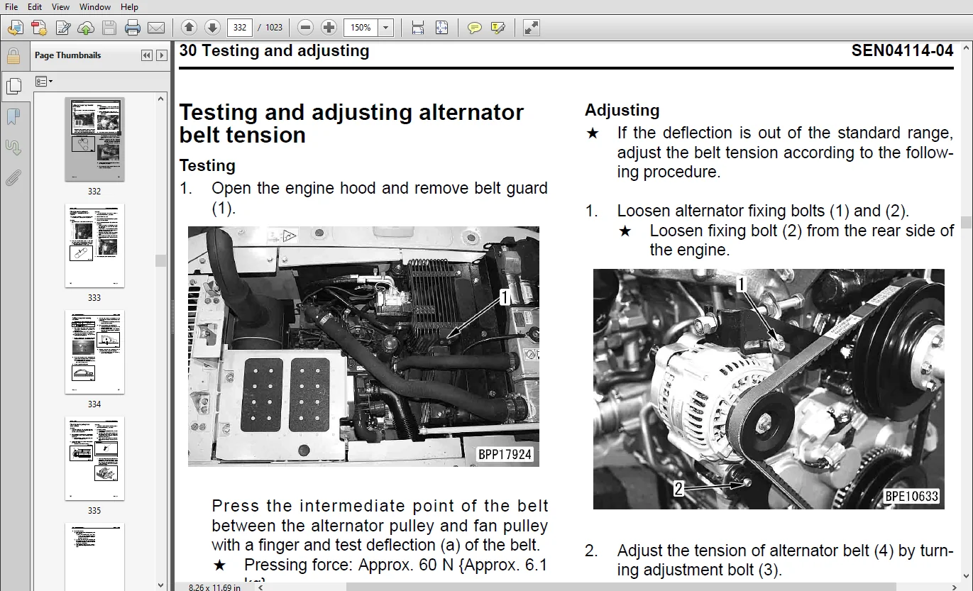
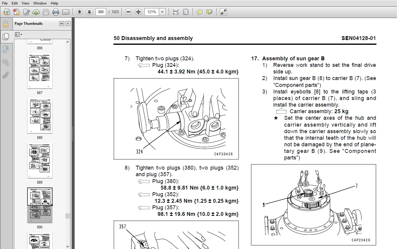
Cover....................................................................................................   1
00 Index and foreword....................................................................................   0
	Index................................................................................................   3
		Composition of shop m............................................................................   4
		Table of cont....................................................................................   6
	Foreword and general information.....................................................................  16
		Safety notice....................................................................................  17
		How to read the shop manual......................................................................  22
		Explanation of terms for maintenance standard....................................................  24
		Handling of electric equipment and hydraulic component...........................................  26
		Handling of connectors newly used for engines....................................................  35
		How to read electric wire code...................................................................  38
		Precautions when carrying out operation..........................................................  41
		Method of disassembling and connecting push-pull type coupler....................................  44
		Standard tightening torque table.................................................................  47
		Conversion table.................................................................................  51
01 Specification.........................................................................................   0
	Specification and technical data.....................................................................  58
		Specification dimension drawings.................................................................  59
		Working range diagram............................................................................  60
		Specifications...................................................................................  61
		List of weights..................................................................................  65
		List of lubricant and coolant to be filled.......................................................  67
10 Structure, function and maintenance standard..........................................................   0
	Engine and cooling system............................................................................  70
		Engine mount.....................................................................................  71
		PTO..............................................................................................  72
		Cooling system...................................................................................  73
	Power train..........................................................................................  76
		Power train......................................................................................  77
		Swing circle.....................................................................................  78
		Swing machinery..................................................................................  79
	Undercarriage and frame..............................................................................  82
		Track frame......................................................................................  83
		Idler cushion....................................................................................  84
		Idler............................................................................................  85
		Track roller.....................................................................................  86
		Carrier roller...................................................................................  87
		Sprocket.........................................................................................  88
		Track shoe.......................................................................................  89
	Hydraulic system, Part 1.............................................................................  94
		Hydraulic equipment layout drawing...............................................................  95
		Valve control....................................................................................  97
		Hydraulic tank and filter........................................................................  99
		Hydraulic pump................................................................................... 101
	Hydraulic system, Part 2............................................................................. 130
		Control valve.................................................................................... 131
		CLSS............................................................................................. 141
		Functions and operation by valve................................................................. 145
	Hydraulic system, Part 3............................................................................. 176
		PPC valve........................................................................................ 177
		Swing motor...................................................................................... 192
		Travel motor..................................................................................... 200
		Center swivel joint.............................................................................. 209
		Solenoid valve................................................................................... 211
		Accumulator...................................................................................... 215
		Holding valve.................................................................................... 217
		Hydraulic cylinder............................................................................... 223
	Work equipment....................................................................................... 226
		Work equipment................................................................................... 227
		Dimensions of components......................................................................... 229
	Cab and its attachments.............................................................................. 234
		Air conditioner.................................................................................. 235
	Electrical system.................................................................................... 239
		Electronic control system........................................................................ 240
		Machine monitor sy............................................................................... 272
		KOMTRAX system................................................................................... 286
		Sensor........................................................................................... 288
20 Standard value table..................................................................................   0
	Standard service value table......................................................................... 238
		Standard value table for engine related parts.................................................... 297
		Standard value table for chassis related parts................................................... 298
30 Testing and adjusting.................................................................................   0
	Testing and adjusting, Part 1........................................................................ 308
		Tools for testing, adjusting, and troubleshooting................................................ 310
		Sketches of special tools........................................................................ 315
		Testing engine speed............................................................................. 316
		Testing exhaust temperature...................................................................... 317
		Checking exhaust gas color....................................................................... 318
		Adjusting valve clearance........................................................................ 319
		Testing compression pressure..................................................................... 321
		Testing blow-by pressure......................................................................... 323
		Testing engine oil pressure...................................................................... 324
		Reduced cylinder mode operation.................................................................. 325
		No-injection cranking............................................................................ 325
		Handling fuel system parts....................................................................... 326
		Releasing residual pressure from fuel system..................................................... 326
		Testing fuel pressure............................................................................ 327
		Testing fuel return rate and fuel leakage........................................................ 328
		Bleeding air from fuel circuit................................................................... 330
		Checking fuel circuit for leakage................................................................ 331
		Testing and adjusting alternator belt tension.................................................... 332
		Checking and adjusting air conditioner compressor belt tension................................... 333
		Testing swing circle bearing clearance........................................................... 334
		Checking and adjusting track shoe tension........................................................ 335
		Testing and adjusting oil pressure in work equipment, swing, and travel circuits................. 337
		Testing control circuit basic pressure........................................................... 340
		Testing and adjusting oil pressure in pump PC control circuit.................................... 341
		Testing and adjusting oil pressure in pump LS control circuit.................................... 344
		Testing solenoid valve output pressure........................................................... 347
		Testing PPC valve output pressure................................................................ 351
		Adjusting play of work equipment and swing PPC valves............................................ 352
		Checking parts which cause hydraulic drift of work equipment..................................... 353
		Testing and adjusting travel deviation........................................................... 355
		Releasing residual pressure from hydraulic circuit............................................... 357
		Testing oil leakage.............................................................................. 358
		Bleeding air from each part...................................................................... 361
		Checking cab tipping stopper..................................................................... 363
		Installation and adjustment of mirrors and camera................................................ 364
		Inspection of air conditioner Recirc/Fresh air filter............................................ 373
	Testing and adjusting, Part 2........................................................................ 376
		Special functions of machine monitor............................................................. 377
	Testing and adjusting, Part 3........................................................................ 428
		Handling voltage circuit of engine controller.................................................... 429
		Preparation work for troubleshooting of electrical system........................................ 430
		Procedure for testing diodes..................................................................... 435
		Pm Clinic service................................................................................ 436
40 Troubleshooting.......................................................................................   0
	Failure code table and fuse locations................................................................ 442
		Failure code table............................................................................... 443
		Fuse locations................................................................................... 447
	General information on troubleshooting............................................................... 450
		Points to remember when troubleshooting.......................................................... 451
		Sequence of events in troubleshooting............................................................ 452
		Checks before troubleshooting.................................................................... 453
		Classification and procedures for troubleshooting................................................ 454
		Information in troubleshooting table............................................................. 455
		Phenomena looking like troubles and troubleshooting Nos.......................................... 457
		Connection table for connector pin numbers....................................................... 460
		T- branch box and T- branch adapter table........................................................ 496
	Troubleshooting by failure code, Part 1.............................................................. 500
		Failure code [989L00] Engine controller lock caution 1........................................... 502
		Failure code [989M00] Engine controller lock caution 2........................................... 502
		Failure code [989N00] Engine controller lock caution 3........................................... 503
		Failure code [AA10NX] Air cleaner clogging....................................................... 504
		Failure code [AB00KE] Charge voltage low......................................................... 505
		Failure code [B@BAZG] Eng oil press. low......................................................... 507
		Failure code [B@BAZK] Eng oil level low.......................................................... 508
		Failure code [B@BCNS] Eng coolant overheat....................................................... 509
		Failure code [B@BCZK] Eng water level low........................................................ 511
		Failure code [B@HANS] Hydr oil overheat.......................................................... 513
		Failure code [CA111] ECM critical internal failure............................................... 515
		Failure code [CA115] Eng Ne and Bkup speed sensor error.......................................... 518
		Failure code [CA122] Charge air press sensor high error.......................................... 519
		Failure code [CA123] Charge air press sensor low error........................................... 521
		Failure code [CA131] Throttle sensor high error.................................................. 523
		Failure code [CA132] Throttle sensor low error................................................... 525
		Failure code [CA144] Coolant temp. sensor high error............................................. 527
		Failure code [CA145] Coolant temp. sensor low error.............................................. 529
		Failure code [CA153] Charge air temp. sensor high error.......................................... 531
		Failure code [CA154] Charge air temp. sensor low error........................................... 533
		Failure code [CA155] Chg air temp high speed derate.............................................. 533
		Failure code [CA187] Sensor sup. 2 volt. low error............................................... 534
		Failure code [CA221] Ambient air press. sensor high error........................................ 535
		Failure code [CA222] Ambient air press. sensor low error......................................... 537
		Failure code [CA227] Sensor sup. 2 volt. high error.............................................. 538
		Failure code [CA234] Eng. overspeed.............................................................. 539
		Failure code [CA238] Ne speed sensor sup. volt. error............................................ 541
		Failure code [CA271] IMV/PCV1 short error........................................................ 543
		Failure code [CA272] IMV/PCV1 open error......................................................... 544
		Failure code [CA322] Injector #1 (L #1) system open/short error.................................. 545
		Failure code [CA324] Injector #3 (L #3) system open/short error.................................. 547
		Failure code [CA331] Injector #2 (L #2) system open/short error.................................. 549
		Failure code [CA332] Injector #4 (L #4) system open/short error.................................. 551
	Troubleshooting by failure code, Part 2.............................................................. 554
		Failure code [CA342] Calibration code incompatibility............................................ 556
		Failure code [CA351] Inj. drive circuit error.................................................... 557
		Failure code [CA352] Sensor sup. 1 volt. low error............................................... 560
		Failure code [CA386] Sensor sup. 1 volt. high error.............................................. 561
		Failure code [CA435] Abnormality in engine oil pressure switch................................... 563
		Failure code [CA441] Battery voltage low error................................................... 564
		Failure code [CA442] Battery voltage high error.................................................. 565
		Failure code [CA449] Rail press. very high error................................................. 566
		Failure code [CA451] Rail press. sensor high error............................................... 567
		Failure code [CA452] Rail press. sensor low error................................................ 569
		Failure code [CA488] Chg air temp high torque derate............................................. 570
		Failure code [CA553] Rail press. high error...................................................... 571
		Failure code [CA559] Rail press. low error....................................................... 572
		Failure code [CA689] Eng. Ne speed sensor error.................................................. 575
		Failure code [CA731] Eng. Bkup speed sensor phase error.......................................... 577
		Failure code [CA757] All persistent data lost error.............................................. 578
		Failure code [CA778] Eng. Bkup speed sensor error................................................ 579
		Failure code [CA1633] KOMNET datalink timeout error.............................................. 581
		Failure code [CA2185] Throttle sens. sup. volt. high error....................................... 583
		Failure code [CA2186] Throttle sens. sup. volt. low error........................................ 585
		Failure code [CA2249] Rail press. very low error................................................. 585
		Failure code [CA2311] Abnormality in IMV solenoid................................................ 586
		Failure code [D110KB] Battery relay drive short.................................................. 587
		Failure code [D19JKZ] Personal code relay abnormality............................................ 589
		Failure code [D862KA] GPS antenna discon......................................................... 591
		Failure code [DA22KK] Pump solenoid power low error.............................................. 593
		Failure code [DA25KP] 5V sensor 1 power abnormality.............................................. 595
		Failure code [DA26KP] 5V sensor 2 power abnormality.............................................. 598
		Failure code [DA29KQ] Model selection abnormality................................................ 599
	Troubleshooting by failure code, Part 3.............................................................. 602
		Failure code [DA2RMC] CAN discon (Pump controller detected)...................................... 605
		Failure code [DAF8KB] Short circuit in camera power supply....................................... 607
		Failure code [DAFGMC] GPS module error........................................................... 609
		Failure code [DAFRMC] CAN discon (Monitor detected).............................................. 611
		Failure code [DGH2KB] Hydr oil sensor short...................................................... 613
		Failure code [DHPAMA] Pump press sensor abnormality.............................................. 615
		Failure code [DHSFMA] Travel left forward PPC press sensor abnormality........................... 617
		Failure code [DHSGMA] Travel right forward PPC press sensor abnormality.......................... 619
		Failure code [DHSHMA] Travel left reverse PPC press sensor abnormality........................... 621
		Failure code [DHSJMA] Travel right reverse PPC press sensor abnormality.......................... 623
		Failure code [DHX1MA] Overload sensor abnormality (Analog)....................................... 625
		Failure code [DV20KB] Travel alarm short circuit................................................. 626
		Failure code [DW43KA] Travel speed sol discon.................................................... 627
		Failure code [DW43KB] Travel speed sol short..................................................... 628
		Failure code [DW45KA] Swing brake sol discon..................................................... 629
		Failure code [DW45KB] Swing brake sol short...................................................... 631
		Failure code [DW91KA] Travel junction sol discon................................................. 633
		Failure code [DW91KB] Travel junction sol short.................................................. 635
		Failure code [DWJ0KA] Merge-divider sol discon................................................... 637
		Failure code [DWJ0KB] Merge-divider sol short.................................................... 639
		Failure code [DWK0KA] 2-stage relief sol discon.................................................. 641
		Failure code [DWK0KB] 2-stage relief sol short................................................... 643
	Troubleshooting by failure code, Part 4.............................................................. 646
		Failure code [DXA8KA] PC-EPC sol discon.......................................................... 647
		Failure code [DXA8KB] PC-EPC sol short........................................................... 649
		Failure code [DXE4KA] Service current EPC discon................................................. 651
		Failure code [DXE4KB] Service current EPC short.................................................. 653
		Failure code [DY20KA] Wiper working abnormality.................................................. 655
		Failure code [DY20MA] Wiper parking abnormality.................................................. 657
		Failure code [DY2CKA] Washer drive discon........................................................ 659
		Failure code [DY2CKB] Washer drive short......................................................... 661
		Failure code [DY2DKB] Wiper drive (for) short.................................................... 663
		Failure code [DY2EKB] Wiper drive (rev) short.................................................... 665
	Troubleshooting of electrical system (E-mode)........................................................ 668
		Before carrying out troubleshooting of electrical system......................................... 670
		Information in troubleshooting table............................................................. 672
		E-1 When starting switch turned ON, machine monitor displays nothing............................. 673
		E-2 When starting switch turned ON (before starting engine), basic check item lights up.......... 675
		E-3 Engine does not start (Engine does not turn)................................................. 678
		E-4 Preheater does not operate................................................................... 681
		E-5 Automatic warm-up system does not operate (in cold season)................................... 683
		E-6 All work equipment, swing, and travel mechanism do not move or cannot be locked.............. 685
		E-7 Precaution lights up while engine is running................................................. 687
		E-8 Emergency stop item lights up while engine is running........................................ 692
		E-9 Engine coolant temperature gauge does not indicate normally.................................. 693
		E-10 Hydraulic oil temperature gauge does not indicate normally.................................. 694
		E-11 Fuel level gauge does not indicate normally................................................. 696
		E-12 Contents of display by machine monitor are different from applicable machine................ 698
		E-13 Machine monitor does not display some items................................................. 698
		E-14 Function switch does not work............................................................... 698
		E-15 Auto-decelerator does not operate normally.................................................. 699
		E-16 Working mode does not change................................................................ 700
		E-17 Travel speed does not change................................................................ 701
		E-18 Alarm buzzer cannot be stopped.............................................................. 702
		E-19 Windshield wiper and window washer do not operate........................................... 703
		E-20 Power maximizing function does not operate normally......................................... 707
		E-21 Swing holding brake does not operate normally............................................... 709
		E-22 Travel alarm does not sound or does not stop sounding....................................... 711
		E-23 Air conditioner does not operate normally (including air conditioner abnormality record).... 712
		E-24 While starting switch is in OFF position, service meter is not displayed.................... 724
		E-25 Machine monitor cannot be set in service mode............................................... 724
		E-26 Monitoring function does not display lever control signal normally.......................... 725
		E-27 KOMTRAX system does not operate normally.................................................... 741
	Troubleshooting of hydraulic and mechanical system (H-mode).......................................... 744
		Information contained in troubleshooting table................................................... 746
		System chart for hydraulic and mechanical systems................................................ 747
		H-1 Speed or power of all work equipment, swing, and travel are low.............................. 749
		H-2 Engine speed sharply drops or engine stalls.................................................. 750
		H-3 No work equipment, travel and swing move..................................................... 751
		H-4 Abnormal noise is heard from around hydraulic pump........................................... 751
		H-5 Fine control mode does not function.......................................................... 752
		H-6 Speed or power of boom is low................................................................ 753
		H-7 Speed or power of arm is low................................................................. 754
		H-8 Speed or power of bucket is low.............................................................. 755
		H-9 Work equipment does not move in its single operation......................................... 756
		H-10 Hydraulic drift of work equipment is large.................................................. 757
		H-11 Time lag of work equipment is large......................................................... 758
		H-12 Power maximizing function does not operate normally......................................... 758
		H-13 Work equipment loaded more is slower during compound operation.............................. 759
		H-14 Boom RAISE speed is low in compound operation of swing + boom RAISE......................... 759
		H-15 Travel speed lowers largely during compound operation of work equipment/swing + travel...... 760
		H-16 Machine deviates during travel.............................................................. 761
		H-17 Travel speed is low......................................................................... 762
		H-18 Machine cannot be steered easily or steering power is low................................... 763
		H-19 Travel speed does not change or it is kept low or high...................................... 764
		H-20 Track does not move (Only either side)...................................................... 764
		H-21 Machine does not swing...................................................................... 765
		H-22 Swing acceleration or swing speed is low.................................................... 766
		H-23 Excessive overrun when stopping swing....................................................... 767
		H-24 When upper structure stops swinging, it makes large shock................................... 768
		H-25 When upper structure stops swinging, it makes large sound................................... 768
		H-26 Hydraulic drift of swing is large........................................................... 769
		H-27 Flow rate in attachment circuit cannot be adjusted.......................................... 770
	Troubleshooting of engine (S-mode)................................................................... 772
		Method of using troubleshooting chart............................................................ 775
		S-1 Starting performance is poor................................................................. 779
		S-2 Engine does not start........................................................................ 780
		S-3 Engine does not pick up smoothly............................................................. 783
		S-4 Engine stops during operations............................................................... 784
		S-5 Engine does not rotate smoothly.............................................................. 785
		S-6 Engine lacks output (or lacks power)......................................................... 786
		S-7 Exhaust smoke is black (incomplete combustion)............................................... 787
		S-8 Oil consumption is excessive (or exhaust smoke is blue)...................................... 788
		S-9 Oil becomes contaminated quickly............................................................. 789
		S-10 Fuel consumption is excessive............................................................... 790
		S-11 Oil is in coolant (or coolant spurts back or coolant level goes down)....................... 791
		S-12 Oil pressure drops.......................................................................... 792
		S-13 Oil level rises (Entry of coolant or fuel).................................................. 793
		S-14 Coolant temperature becomes too high (overheating).......................................... 794
		S-15 Abnormal noise is made...................................................................... 795
		S-16 Vibration is excessive...................................................................... 796
50 Disassembly and assembly..............................................................................   0
	General information on disassembly and assembly...................................................... 798
		How to read this manual.......................................................................... 799
		Coating materials list........................................................................... 801
		Special tool list................................................................................ 804
		Sketch of special tool........................................................................... 808
	Engine and cooling system............................................................................ 814
		Removal and installation of fuel supply pump assembly............................................ 815
		Removal and installation of fuel injector assembly............................................... 818
		Removal and installation of front oil seal....................................................... 821
		Removal and installation of rear oil seal........................................................ 823
		Removal and installation of cylinder head assembly............................................... 826
		Removal and installation of radiator assembly.................................................... 836
		Removal and installation of aftercooler assembly................................................. 838
		Removal and installation of work equipment oil cooler assembly................................... 840
		Removal and installation of engine and work equipment pump assembly.............................. 842
		Removal and installation of fuel tank assembly................................................... 850
	Power train.......................................................................................... 854
		Removal and installation of travel motor and final drive assembly................................ 855
		Disassembly and assembly of travel motor and final drive assembly................................ 857
		Removal and installation of swing motor and swing machinery assembly............................. 894
		Disassembly and assembly of swing machinery assembly............................................. 896
		Removal and installation of swing circle assembly................................................ 902
	Undercarriage and frame.............................................................................. 904
		Disassembly and assembly of track roller......................................................... 905
		Disassembly and assembly of idler assembly....................................................... 908
		Disassembly and assembly of recoil spring........................................................ 911
		Spreading and installation of track shoe assembly................................................ 914
		Removal and installation of sprocket............................................................. 916
		Removal and installation of revolving frame assembly............................................. 917
		Removal and installation of counterweight assembly............................................... 919
	Hydraulic system..................................................................................... 922
		Removal and installation of center swivel joint assembly......................................... 923
		Disassembly and assembly of center swivel joint assembly......................................... 925
		Removal and installation of hydraulic tank assembly.............................................. 926
		Removal and installation of work equipment pump assembly......................................... 929
		Removal and installation of control valve assembly............................................... 933
		Disassembly and assembly of control valve assembly............................................... 937
		Disassembly and assembly of work equipment PPC valve assembly.................................... 949
		Disassembly and assembly of travel PPC valve assembly............................................ 951
		Disassembly and assembly of hydraulic cylinder assembly.......................................... 954
	Work equipment....................................................................................... 962
		Removal and installation of work equipment assembly.............................................. 963
	Cab and its attachments.............................................................................. 968
		Removal and installation of operator's cab assembly.............................................. 969
		Removal and installation of operator cab glass (stuck glass)..................................... 972
		Removal and installation of front window assembly................................................ 982
		Removal and installation of floor frame assembly................................................. 989
	Electrical system.................................................................................... 994
		Removal and installation of air compressor assembly.............................................. 995
		Removal and installation of air conditioner condenser............................................ 996
		Removal and installation of air compressor unit assembly......................................... 997
		Removal and installation of KOMTRAX communication modem assembly.................................1000
		Removal and installation of monitor assembly.....................................................1001
		Removal and installation of pump controller assembly.............................................1003
		Removal and installation of engine controller assembly...........................................1005
90 Diagrams and drawings.................................................................................   0
	Hydraulic diagrams and drawings......................................................................1008
		Hydraulic circuit diagram (1/2)..................................................................1010
		Hydraulic circuit diagram (2/2)..................................................................1011
	Electrical diagrams and drawings.....................................................................1014
		Electrical circuit diagram (1/5).................................................................1016
		Electrical circuit diagram (2/5).................................................................1017
		Electrical circuit diagram (3/5).................................................................1018
		Electrical circuit diagram (4/5).................................................................1019
		Electrical circuit diagram (5/5).................................................................1020
		Connectors table and arrangement drawing.........................................................1021
KOMATSU PC130-8 HYDRAULIC EXCAVATOR SHOP MANUAL SEN03763-10 – PDF DOWNLOAD:
IMAGES PREVIEW OF THE MANUAL:
PLEASE NOTE:
- This is the SAME exact manual used by your dealers to fix your vehicle.
- The same can be yours in the next 2-3 mins as you will be directed to the download page immediately after paying for the manual.
- Any queries / doubts regarding your purchase, please feel free to contact [email protected]


Westley Bradley –